Clinton FL-20A User manual

Clinton Instrument Company
295 East Main Street
Clinton, CT 06413 USA
Telephone: 860.669.7548 Fax: 860.669.3825
www.clintoninstrument.com
Model FL-20ACable Fault Locator
Instruction Manual

Rev J 11/19

MODEL FL-20A
Cable Fault Locator
Reels of rejected multi-conductor and shielded cable sit-
ting on the production oor are an expensive problem.
Until now, nding opens and shorts with an analog cable
fault locator took expertise and patience, since the procedure
required tedious meter and sensitivity adjustments as well as
mathematical calculation once the test was completed.
The digital FL-20A automates cable fault detection,
greatly reducing the time and training required to nd these
problems. Opens, metallic shorts, or high voltage shorts
between conductors or between conductor and shield are
pinpointed quickly and with ease. The operator simply con-
nects the FL-20A test probes to each end of the cable under
test, enters the cable length on the digital touch screen, and
selects “Shorts” or “Opens” to begin the test. The unit
quickly calculates the distance of the fault site from each test
probe, displays the location in feet or meters, and provides
a suggested trim area. The failure can then be cut out or
repaired and the remaining good product salvaged, resulting
in great savings to the producer.
>> Quickly locates opens, shorts and high
voltage shorts in cable lengths
>> Fully automated testing
>> Simple to operate
>> Color touch screen
>> Compact, lightweight unit
>> CE approved
The FL-20A Cable Fault Locator, a compact 15”W x 14”D
x 10”H weighing only 38 lbs., is signicantly smaller and lighter
than its predecessors. It promises a great return on investment
by salvaging expensive cable assemblies and lowering the costs
associated with salvage.
Sample display screens

295 East Main St. • Clinton, CT 06413 USA • Tel: 860.669.7548 • Fax: 860.669.3825 • www.clintoninstrument.com
Fault Definitions:
Open.. ................................ A condition where a single conductor has no
continuity from one end to the other.
Metallic Short ...................... Two conductors without insulation or a conductor and
a shield which physically come into contact with one
another.
High Voltage Short .............. Two conductors or a conductor and a shield which
have no insulation between them but do not contact
one another.
Voltage Test Range ..............0-20KV D.C.
Display ............................... 6-inch backlit color TFT touch screen.
Output Current .....................6 ma. maximum.
FL-20A
SPECIFICATIONS
Equipment Accuracy .............Better than 1% of total cable length (dependent on
accuracy of actual cable footage and product uniformity).
Cable Loop Resistance
Metallic Short .............50 milliohms minimum.
High Voltage Short ......300 milliohms minimum.
Dimensions:
FL-20A ....................... 15”W x 14”D x 10”H.
FL-20A with X3F .........15”W x 14”D x 25.5”H.
Test Leads...................10’ standard, 20 & 30 ft. available.
Weight ...............................38 lbs. (17.3kg.).
Power Requirements ............100 - 240 volts AC, 50/60 Hz 2 amps.
*dependent on accuracy of actual cable footage and product uniformity.
Specifications subject to change without notice. 11/11 EN
z
Shorts
z
Typical Lead Connections
Opens
Green
Blue
(Ground Strap)
Green
Blue
Red
Red
Coaxial Cable
Top of Reel Bottom of reel
Multi Conductor Cable
Green
(Ground Strap)
Green
Coaxial Cable
Top of Reel Bottom of reel
Multi Conductor Cable
Blue Red
Blue Red
1
1
2
2
3
3
4
4
A A
B B
C C
D D
DWG NO:
ALL DIMENS ION IN INCHE S:
TOLERANCES:
FRACTIONAL: ±1/64
DECIMAL:
2 PLACES: ±.015
3 PLACES: ±.010
ANGULAR: ±1~
UNLESS OTHERWISE NOTED
USED IN:
APPROVED:
12/10/2009
DRAWN:
tlane
FL-20
C
DATE:
295 EAST MAIN STREET, CLINTON, CT 06413
PHONE: ( 860) 669-7548 F AX: (860) 669-3825
THIS DRAWING IS THE PROPERTY
OF THE CLINTO N INST RUMENT
COMPANY, INC. THE INFORMATION
CONT AINED HEREON MAY NOT
BE REPRODUCED OR DISTRIBUTED
WITHOUT T HE EXPRESS PER-
MISSION OF THE CLINTON
INSTRUMENT CO.
the clinton instrument company
C
TITLE:
SIZE SHEET 1 OF 1
CHECKED QA: REV

Table of Contents
Safety ........................................................................................................................................ 1
Installation ............................................................................................................................... 4
Denitions ............................................................................................................................... 7
FL-20A Controls .................................................................................................................... 9
Settings Menu........................................................................................................................11
Testing Large Cables with the FL-20A ............................................................................17
Performing a Shorts Test.....................................................................................................18
Performing an Open Tests.................................................................................................. 20
Performing a Hi-Pot Test.................................................................................................... 22
Calibration ............................................................................................................................24
Maintenance ..........................................................................................................................26
Cable Capacitance Chart......................................................................................................27
Cable Loop Resistance Chart..............................................................................................28
Locating Shorts in Medium and High Voltage Cables.................................................... 29
How to Use the 91785 FL Test Box.................................................................................. 32
Troubleshooting....................................................................................................................34
Replacement Parts ................................................................................................................35
Optional Accessories ........................................................................................................... 36
“Electric Shock Considerations for Electric Vehicle Charging Systems”.................... 37
Warranty.................................................................................................................................44


Declaration of Conformity
Manufacturer: ..............The Clinton Instrument Company
Address: ........................295 East Main Street
Clinton, CT USA 06413
Herewith declares that
The Cable Fault Locator
Type FL-20A
is in conformity with the provisions of the following EEC directives:
89/236/EEC
73/23/EED
Conforms with the emissions requirements of EN 61326-1:2006; Clause 7.2:
CISPR 11 Edition 4:2003 .....Conducted Emissions, Class A
CISPR 11 Edition 4:2003 .....Radiated Emissions, Class A
IEC 61000-3-2:2000..............Harmonics
IEC 61000-3-3:2002..............Flicker
Conforms with the immunity requirements of EN 61326:2006; Table 1:
IEC 61000-4-2:2001..............Electrostatic Discharge
IEC 61000-4-3:2002..............Radiated Immunity
IEC 61000-4-4:2004..............EFT/Burst, Power and I/O Leads
IEC 61000-4-5:2001..............Surge Immunity
IEC 61000-4-6:2003..............Conducted Immunity, Power and I/O Cables
IEC 61000-4-11:2004............Voltage Dips and Interrupts
Conforms to the safety requirements of EN61010.
Clinton, CT USA February 2010
Marianne Szreders
President Ted P. Lane
Chief Engineer


FL-20A Instruction Manual - Page 1
Model FL-20A Cable Fault Locator
Safety
Danger! High Voltage Safety Hazards
Caution--Read before using this equipment.
DISCHARGE ALL CONDUCTORS OF THE TEST CABLE
PRIOR TO CONNECTING TO THE FL-20A. YOU MUST
REMOVE ANY STORED CHARGE FROM THE PREVI-
OUS OPERATION, SUCH AS A HI-POT TEST. A STORED
CHARGE IN THE CABLE CAN KILL!!!
The FL-20A employs high voltage to locate cable faults. It is imperative
that only personnel trained in the dangers of high voltage operate this
equipment. A stored charge in the TEST PRODUCT can be lethal,
even when the cable is no longer attached to the FL-20A. Please read
and understand the manual prior to operating this equipment.
A Warning to Supervisors!
The FL-20A is equipped with such safety features as external and inter-
nal safety interlocks, a red high voltage warning light, grounding sensors,
and password protection. Do not attempt to defeat or bypass any safety
feature. Failure to observe proper safety precautions can result in severe
injury or death!
Supervisory personnel are strongly advised to use the built-in password
protection feature to prevent unauthorized persons from defeating
safety features or changing test parameters. Read the section in Installa-
tion entitled, “Password Protection,” for further information.
A Warning Note to Operators!
When cables are being tested with this or any high voltage equipment,
the possibility of leaving a dangerous charge in the cable is always pres-
ent. Always bunch together and ground all conductors not under test,
including to the cable shield and to the earth ground, using the provided
ground probe. Make sure the test is complete, that the high voltage
indicator lamp is off, and that all leads are shorted to ground before
touching any part of the cables.
Although the high voltage output of the FL-20A is not in itself capable
of delivering a truly dangerous shock, a stored charge in the cable can, if
proper safety precautions are not taken. For this reason, operators and
supervisors should establish rigid safety procedures for the use of this
and all high voltage equipment.
Page 2 - FL-20A Instruction Manual
Model FL-20A Cable Fault Locator
High Voltage Facts
The commonly accepted maximum values of 60 Hz. current passing
through the human adult body which permit a subject to let go of elec-
trodes are nine milliamperes for males and six milliamperes for females.
At 3000 Hz. this value increases to about 22 milliamperes for men or 15
milliamperes for women. DC currents do not present the same let–go
problems, but a subject can readily let go at a level of 60 milliamperes.
A continuous 60 Hz. current above 18 milliamperes stops breathing for
the duration of the shock only. Ventricular brillation may occur above
a level of 67 milliamperes. The reaction current level of 60 Hz. is about
.5 milliamperes. Above this level a muscular reaction can occur which
can cause a secondary accident. The DC and 3 kHz. levels are probably
considerably higher.
Capacitor discharge energy of 50 Joules (watt–seconds) is regarded as
hazardous.
For references, see: Dalziel, Ogden, Abbot, “Effect of Frequency on
Let–Go Currents,” Transactions of A.I.E.E., Volume 62, December
1943, and Dalziel, “Electric Shock Hazard,” I.E.E.E., Spectrum, Febru-
ary 1972.
Safety Symbols
The symbols depicted below are safety symbols placed on the spark test
equipment. It is important to understand the meaning of each.
The Caution symbol found in the instruction manual calls attention to
a procedure, practice, or the like, which if not correctly performed or
adhered to, could result in personal injury or damage to or destruction
of part or all of the product. Do not proceed beyond a Caution symbol
until the indicated conditions are fully understood and met.
Risk of electric shock symbol.
Earth (ground) symbol.
Environmental Conditions
The Model FL-20A Cable Fault Locator is designed to be safe under the
following conditions:
• Indoor use.
• Altitude to 2000 m.
• Temperatures from 5ºC to 40ºC.
• Humidity to 80% R.H. at 31ºC, decreasing linearly to 50% R.H. at

FL-20A Instruction Manual - Page 3
Model FL-20A Cable Fault Locator
40ºC.
The Clinton Instrument Company certies that this equipment met its
published specications at the time of shipment. Clinton further certi-
es that its calibration measurements are traceable to the United States
National Institute of Standards and Technology to the extent allowed
by the Institute’s calibration facility. For customer service or technical
assistance with this equipment, please contact:
The Clinton Instrument Company
295 East Main Street, Clinton, CT 06413 USA
Telephone: 860-669-7548 Fax: 860-669-3825
Website: www.clintoninstrument.com.
email: support@clintoninstrument.com.
Page 4 - FL-20A Instruction Manual
Model FL-20A Cable Fault Locator
Installation
Unpacking
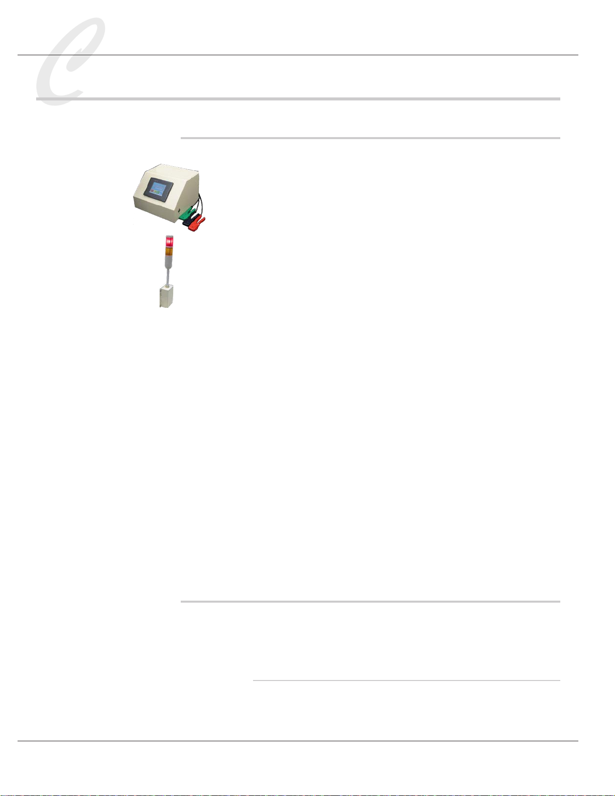
The following items are included in the shipment:
• FL-20A Cable Fault Locator, with a set of 3 test probes (red, blue and
green) connected to the back of the unit
• A green 2-position connector, to be used as a safety interlock if prod-
ucts will be tested in a cage. This will also be used during calibra-
tion.
• X3F Light Tower
• A 4-conductor cable with a 4-pin connector on one end, and a 10-pin
connector on the other, to connect the FL-20A to the X3F
• 4 bolts to mount the X3F to the FL-20A
• A Y- power cord
• 91785 FL Test Box
• (3) 92100 Probe Clip Assemblies (other sizes available)
• An instruction manual
If a printer was ordered, the following items are included:
• Printer
• Printer cable
• Power adapter
• Roll of paper, part no. 91901
Remove the FL-20A and accessories from the carton. Retain the packing
material in the event that the unit is returned for calibration or service at
some future time.
Site Preparation
Caution: The installation procedures listed below are to be performed
by qualied service personnel only. Failure to follow these procedures
may result in danger to personnel and damage to equipment.
Caged Operation
Cables under high voltage test can build up a deadly charge. It is common
practice to enclose cables under test in a caged area to protect workers,
with the FL-20A located outside the cage. When the FL-20A Caged

FL-20A Instruction Manual - Page 5
Model FL-20A Cable Fault Locator
Operation mode is selected, the equipment operator can perform a cable test
by momentarily pressing the safety buttons on the side of the fault locator,
rather than having to press the buttons for the duration of the test. Caged
Operation requires that the high voltage safety interlock on the back of the
unit be connected to the cage door interlock. See “Wiring Requirements” for
external safety interlock wiring instructions.
Wiring Requirements
Mount the X3F Light Tower
Be sure the FL-20A is OFF. Mount the X3F to the right side of the FL-20A,
using the 4 bolts provided.
Locate the 10-pin green terminal block on the back of the X3F, the 4-pin
terminal block on the back of the fault locator, and the 4-conductor cable
supplied with the unit. Plug the 10-pin connector into the X3F 10-pin ter-
minal block and the 4-pin connector into the 4-pin block on the rear panel
of the FL-20A.
When the wiring is complete, plug the Y-power cord into the X3F and the
fault locator.
Ground the chassis
Connect a ground wire to the ground terminal on the rear of the FL-20A
chassis. Connect the other end to earth ground. Use 22 gauge wire or larger.
This is an important safety task that must not be neglected.
Wire the external safety interlock (Caged Operation)
Wire the green 2-position connector to 22 ga. or larger wire and connect to
the 2-pin FL-20A external safety interlock terminal block, found on the rear
of the FL-20A. Connect the other end of the wire to the cage door. If you
will not be using Caged Operation, skip this step.
Printer Installation
1. Plug the power adapter into the connector located on the back right
of the Thermal Receipt Printer.
2. Connect the male end of the printer cable into the back of the
printer and the female end of the printer cable into the FL-20A con-
nector labelled “Printer,” located on the rear of the unit.
3. Make sure paper (Part # 90901) is inserted and fed through the
printer.
4. Press the switch on the back left of the printer to turn ON. The

Page 6 - FL-20A Instruction Manual
Model FL-20A Cable Fault Locator
printer is ready when a green power light shows on front of
printer.
5. Printing occurs when the nal test page (results page) appears
on the FL-20A display screen, as shown in the picture to the left.
Password Protection
The FL-20A offers password protection that can prevent unauthorized
individuals from defeating safety features and changing voltage settings
and test parameters. Using password protection will make your work-
place safer.
After making necessary changes in the Settings menu, go to the Set
Admin Password setting. The default password is 1111. To change it,
press the displayed password to access a keypad. Enter a new 4-digit
password and press OK.
After entering a new password, go to the Lock Settings Menu function
and turn it ON. This will restrict unauthorized personnel from access-
ing the Settings menu. If the new password should be lost, contact the
factory.

FL-20A Instruction Manual - Page 7
Model FL-20A Cable Fault Locator
Denitions
Shorts
Metallic short
A condition where there is direct metal-to-metal contact between two
conductors.
High voltage short
Two conductors without insulation, or a conductor and a shield with no
insulation between them, where there is no direct contact. The condi-
tion is detected only at high voltage when arcing occurs between conduc-
tors.
Intermittent arc
An intermittent arc is a high voltage short present that breaks down mar-
ginally at the selected hi-pot voltage.
Opens
An open is a condition where a single conductor has no continuity from
one end to the other.
Hi-Pot Test
Also called a dielectric withstand test. The purpose of this test is to
charge one conductor to determine if high voltage at a predetermined
level will discharge to ground through the insulation. If too much cur-
rent ows, the conductor is not well insulated and it fails the test.
Loop Resistance
Conductor resistance to the ow of electrical current, measured in
ohms/1,000 feet. Resistance is inversely proportional to the cross-sec-
tional area of the conductor, so when the diameter of the conductor is
doubled, the resistance declines 50 percent. FL-20A tests for metallic
shorts are accurate on conductors with loop resistances of 50 milliohms
or greater. Tests for high voltage shorts are effective on conductors with
resistances of 200-250 milliohms or greater.
Accuracy
The accuracy of the test performed. Ratings are inuenced by cable
characteristics such as low loop resistance. Accuracy is reported as fol-
lows:

Page 8 - FL-20A Instruction Manual
Model FL-20A Cable Fault Locator
Low
There may be multiple faults in the cable, the cable may have low loop
resistance, or the fault is judged to be close to either end.
Standard
The test is considered good, with good results.
Exceptional
The fault location was easily located, and test results are accurate within
1% of the cable length.

FL-20A Instruction Manual - Page 9
Model FL-20A Cable Fault Locator
FL-20A Controls
ON/OFF power switch
This switch is located on the rear panel of the unit.
Ground connection
A 10-32 grounding stud located on the rear panel of the FL-20A chassis.
Wire to earth ground as directed in the Installation section.
External safety interlock (for Caged Operation)
If cables are to be tested in a caged area with the FL-20A located out-
side, the FL-20A external safety interlock must be wired to the cage door
so that cables may be tested only when the cage door is closed. When
the external interlock is engaged and the Caged Operation setting, found
in the Settings menu, is ON, the operator will be required to momentarily
press the FL-20A safety buttons during a test, rather than press them for
the full test. Refer to the section of Caged Operation for wiring details.
The safety interlock is also required for calibration. A two-position con-
nector is supplied for this purpose. Refer to the Calibration section for
instructions.
Front panel touch screen
The touch screen is used to set test parameters, run tests, and view test
results. Never press the touch screen with a tool or sharp object.
Safety buttons
Located on each side of the FL-20A, the safety buttons must be held in
during a shorts or hi-pot test. This is a safety feature that prevents the
operator from touching the charged test cable during a test.
Red and blue test probes
The red probe will connect to one end of a test conductor, and the blue
probe to the opposite end. Review the instructions in the Installation
section on how to properly strip back the conductors and insert them
into the probes. This is an important safety procedure.
Green ground probe
The green ground probe is used to make connections to the reference

Page 10 - FL-20A Instruction Manual
Model FL-20A Cable Fault Locator
conductor and to ground the test cable. Review the instructions in the
test sections on how to properly strip back the conductors and insert
them into the probe. This is an important safety procedure.
X3F Light Tower
When the X3F is properly installed, the red High Voltage light will go
ON when high voltage is present on the FL-20A test probes.
The yellow Test In Progress light will ash during a test.
Warning: when the red High Voltage light on the X3F is illu-
minated, do not touch the red and blue probes or the test cable,
because a charge is present. If the cable capacitance is large, the
light may be illuminated for several seconds after the test is com-
plete.

FL-20A Instruction Manual - Page 11
Model FL-20A Cable Fault Locator
Settings Menu
Test parameters are found on the touch screen Settings menu. They are
saved in memory even when the FL-20A is off. To view or change test
parameters, turn on the FL-20A power switch, which is located on the
back of the unit. The FL-20A will take a few moments to boot up. Do
not touch the screen until the Clinton logo appears. The main menu
will appear.
Press the Settings button.
The Password Entry screen will appear. Click inside the Password box
and enter the password on the keypad and press OK. The default pass-
word is 1111. Press NEXT. (If you wish to change the password, go to
Set Admin Password, on a later page of the Settings menu.)
The rst page of the Settings menu will appear.
Press Pg Down to the next few pages of the Settings menu to access the
following global settings: Calibration, Language, Caged Operation and
Unit of Measure. These settings apply to all Opens, Shorts and Hi-Pot
Testing.
Global Settings
Global settings such as Calibration, Language, Caged Operation, and
Unit of Measure apply to Opens, Shorts and Hi-Pot tests. They are found
in the several pages of the Settings Menu. To view or modify a setting,
press the appropriate button to access the subscreen. Addtional screens
such as System Information, System Errors, Set System Defaults, and
Set Admin Password are also included in the Settings menu.
Calibration
This setting allows the user to calibrate the FL-20A output voltage and
voltage reporting. Refer to the section entitled,”Calibration,” for spe-
cic instructions.
Language
Flag icons representing the languages that are available on the FL-20A are
displayed here. The languages are English, Japanese, Spanish, German,
French, Italian, Swedish, and Chinese. Press the ag icon of your choice.
The default setting is English.
Caged Operation
Cables under high voltage test can build up a deadly charge that remains

Page 12 - FL-20A Instruction Manual
Model FL-20A Cable Fault Locator
until the conductors are intentionally discharged. For this reason, an
operator using the FL-20A in an open area is required to hold in the
safety buttons on each side of the fault locator. This is a safety precaution
to prevent him or her from touching the test cable while it is charged. In
this situation, Caged Operation is OFF. This is the default setting.
Do not attempt to defeat the safety buttons. Failure to observe
proper safety precautions can result in severe injury or death!
Because it is common practice to use a fault locator in a caged area to
protect workers, the Caged Operation setting can be changed to ON, and
the FL-20A operator can perform a test without pressing in the safety
buttons on each side of the fault locator. To turn ON the Caged Opera-
tion setting, the external interlock on the back of the FL-20A unit must
be connected to the cage door. Press NEXT to access the next screen.
Then press the ON/OFF area of the screen to change Caged Operation
to ON. Press ACCEPT.
Unit of Measure
Test cable lengths may be displayed in feet or meters. The unit of mea-
sure cannot be changed during a test. Press the displayed choice to
toggle between Feet or Meters.
System Information
FL-20A rmware and software version numbers are stored here. During
troubleshooting, you may be asked for this information by a Clinton
technician.
System Errors
System error information is stored here. A Clinton technician may
request that you access this information during troubleshooting if the
yellow or red lights on the back of the FL-20A are ashing.
Set System Defaults
The Set System Defaults RESTORES system defaults. Restoring System
Defaults does not affect calibration.
Set Admin Password
When Lock Settings is ON, a password is required to access the Settings
menu. Reserving global setting access to supervisory personnel prevents
unauthorized individuals from changing test parameters or defeating
safety features. The default password is 1111. To change it, press the
displayed password to access a keypad. Enter a new 4-digit password
and press the check mark/accept button.
After changing the password, turn Locked Settings Menu ON to prevent
unauthorized access to the Settings menu.
Table of contents
Other Clinton Test Equipment manuals


Popular Test Equipment manuals by other brands


Redtech
Redtech TRAILERteck T05 user manual

Venmar
Venmar AVS Constructo 1.0 HRV user guide

Test Instrument Solutions
Test Instrument Solutions SafetyPAT operating manual

Hanna Instruments
Hanna Instruments HI 38078 instruction manual

Kistler
Kistler 5495C Series instruction manual

Waygate Technologies
Waygate Technologies DM5E Basic quick start guide

StoneL
StoneL DeviceNet CK464002A manual

Seica
Seica RAPID 220 Site preparation guide

Kingfisher
Kingfisher KI7400 Series Training manual

Kurth Electronic
Kurth Electronic CCTS-03 operating manual

SMART
SMART KANAAD SBT XTREME 3G Series user manual

Agilent Technologies
Agilent Technologies BERT Serial Getting started