Clinton DC-1 User manual

DC-1, -10, -20B Instruction Manual –Page 0
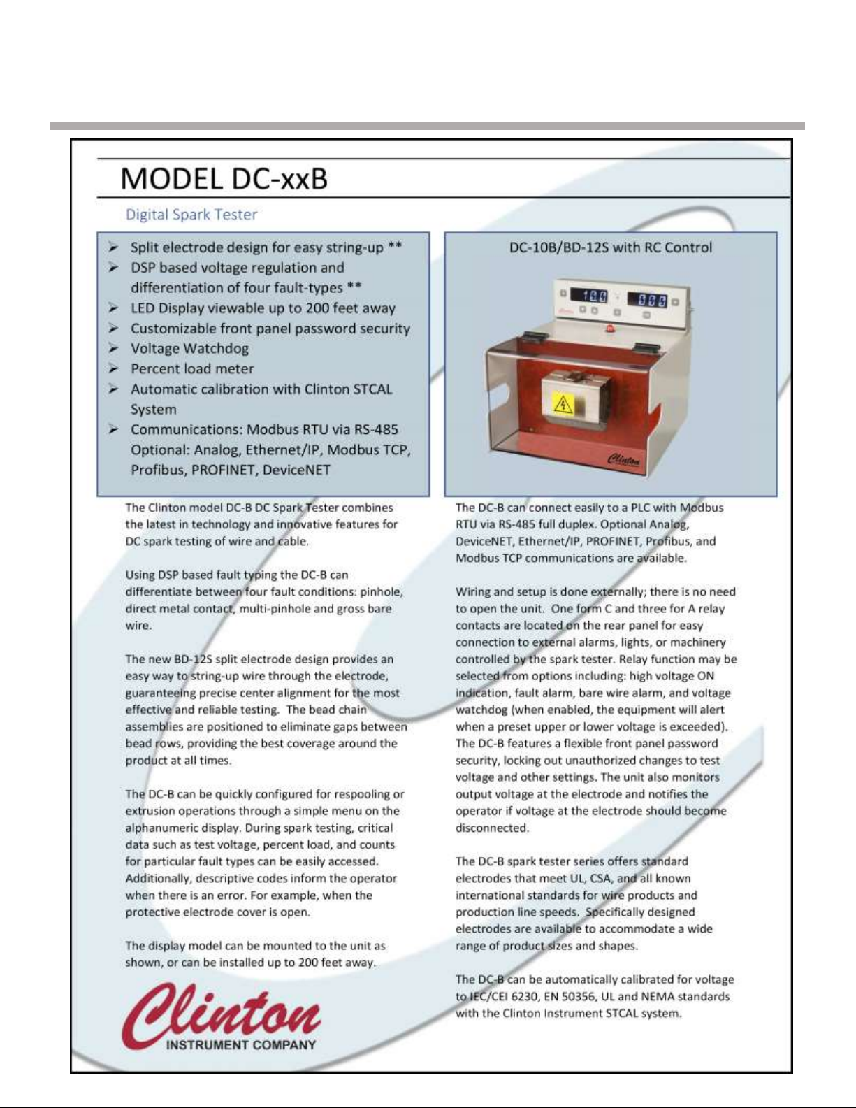
Models DC-1, -10 and -20B DC Spark Testers
Instruction Manual
295 East Main Street
Clinton, CT 06413 USA
Telephone: 860.669.7548 Fax: 860.669.3825
www.clintoninstrument.com
DCDC-20B/BD-12S shown with optional X3B Horn/Light Tower
Clinton Instrument Company

Models DC-1, -10, -20B DC Spark Testers
DC-1, -10, -20B Instruction Manual –Page 1
Rev Null b0002 10/11/17

Models DC-1, -10, -20B DC Spark Testers
DC-1, -10, -20B Instruction Manual –Page 2
Contents
DECLARATION OF CONFORMITY........................................................................................................................................................5
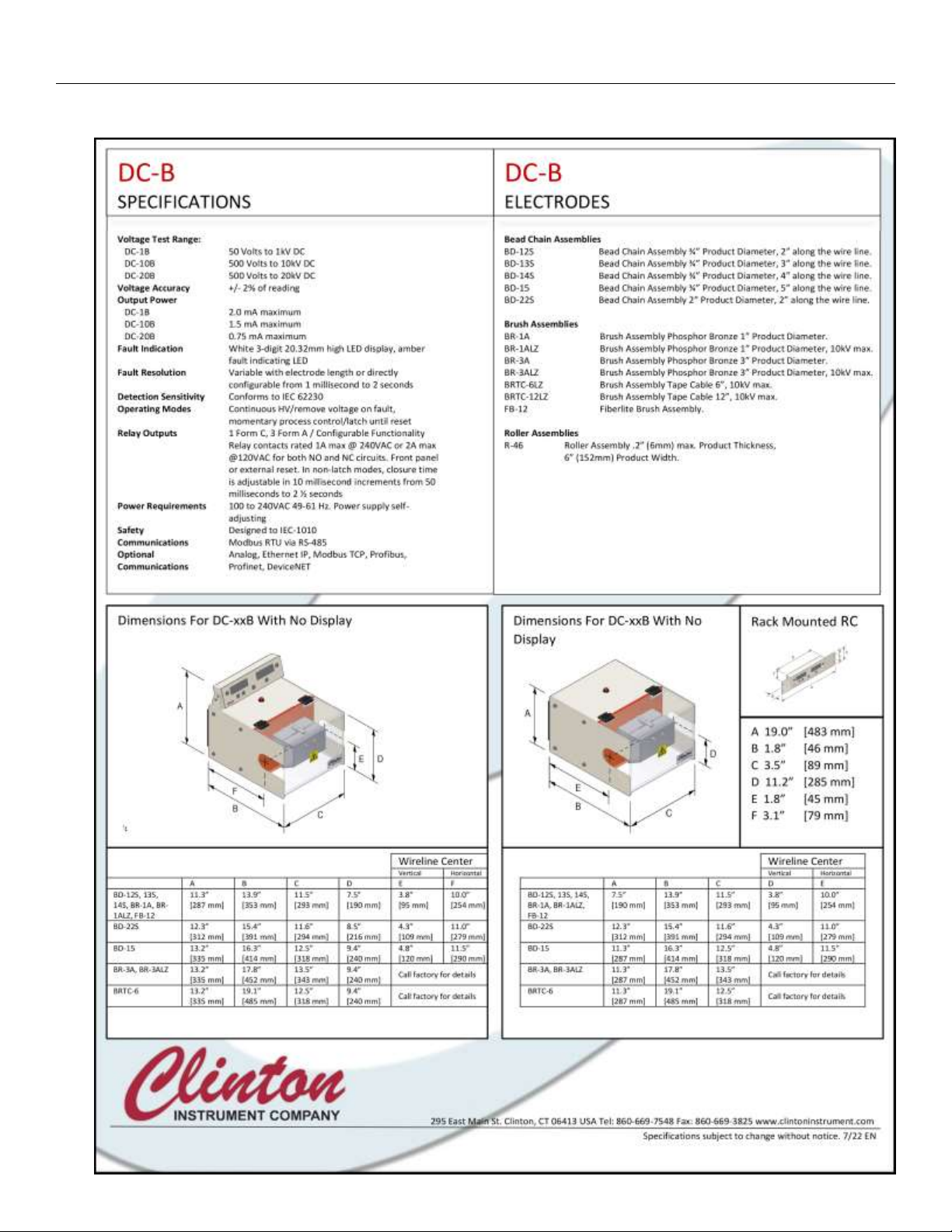
SPECIFICATIONS ................................................................................................................................................................................6
SAFETY ..............................................................................................................................................................................................8
SAFETY SYMBOL .........................................................................................................................................................................................8
ENVIRONMENTAL CONDITIONS...................................................................................................................................................................... 8
AVOID THE RISK OF FIRE! .............................................................................................................................................................................9
CAUTION:PACEMAKER WARNING .................................................................................................................................................................9
ELECTRICAL SHOCK HAZARD FROM PRODUCTION LINE SPARK TESTERS..................................................................................................................9
INSTALLATION .................................................................................................................................................................................11
CAUTION:.............................................................................................................................................................................................11
UNPACKING.............................................................................................................................................................................................11
SITE PREPARATION....................................................................................................................................................................................12
Select a suitable location for the spark tester: ................................................................................................................................ 12
To mount the unit on a horizontal surface: ..................................................................................................................................... 12
To install the unit on a Clinton floor stand: .....................................................................................................................................12
To install RC Display onto the DC-B .................................................................................................................................................13
Provide for ventilation of the Test Module......................................................................................................................................13
POWER WIRING .......................................................................................................................................................................................13
Install an external disconnecting device..........................................................................................................................................13
Mains Power....................................................................................................................................................................................13
Ground the Spark Tester..................................................................................................................................................................13
TERMINAL BLOCK WIRING..........................................................................................................................................................................14
CONNECTING THE SERIAL RS-485 ...............................................................................................................................................................16
CONNECTING TO THE ANALOG INTERFACE (OPTIONAL) ....................................................................................................................................16
INSTALLING THE COMPACTCOM™MODULE (OPTIONAL) ................................................................................................................................. 16
CONNECTING THE X3B (OPTIONAL) .............................................................................................................................................................16
Unpacking the X3B ..........................................................................................................................................................................17
Connecting the X3B ......................................................................................................................................................................... 17
X3B to Spark Tester Connections.....................................................................................................................................................18
SPARK TESTER CONTROLS ...............................................................................................................................................................19
ON/OFF Power Switch ..................................................................................................................................................................... 19
Voltmeter ........................................................................................................................................................................................ 19
“A” Button .......................................................................................................................................................................................19
UP/DOWN ARROW (VOLTAGE ADJUST) buttons............................................................................................................................. 19
Fault Counter...................................................................................................................................................................................19
“B” Button .......................................................................................................................................................................................19
“CR” COUNT RESET button .............................................................................................................................................................. 19
FAULT light ......................................................................................................................................................................................20
“R” RESET button.............................................................................................................................................................................20
High Voltage On Lamp ....................................................................................................................................................................20
Bead Chain Electrode ......................................................................................................................................................................20
Clear Protective Cover ..................................................................................................................................................................... 20
Safety Interlock switch ....................................................................................................................................................................20
Safety end guards............................................................................................................................................................................20
DEFINITION OF TERMS ....................................................................................................................................................................21

Models DC-1, -10, -20B DC Spark Testers
DC-1, -10, -20B Instruction Manual –Page 3
NEW FEATURES ...............................................................................................................................................................................22
DISPLAY: ................................................................................................................................................................................................ 22
FRONT PANEL SECURITY ............................................................................................................................................................................22
BD-12S DESIGN (PATENT PENDING)..........................................................................................................................................................22
COMMUNICATION MODULES .....................................................................................................................................................................23
VOLTAGE WATCHDOG ..............................................................................................................................................................................23
FAULT TYPING .........................................................................................................................................................................................23
BACKWARDS COMPATIBLE.........................................................................................................................................................................23
SPARK TESTER CONFIGURATION (FRONT PANEL) ............................................................................................................................24
NAVIGATING THE CONFIGURATION MENU..................................................................................................................................................... 24
RC DISPLAY SECURITY (PIN)....................................................................................................................................................................... 24
CONFIGURATION MENU OPTIONS................................................................................................................................................................25
SPARK TESTER INPUTS.....................................................................................................................................................................29
High Voltage Enable (HVE).............................................................................................................................................................. 29
Fault Reset (FR) ............................................................................................................................................................................... 29
SPARK TESTER OUTPUTS .................................................................................................................................................................29
GENERAL OUTPUTS...................................................................................................................................................................................30
Output Disabled (OFF) .....................................................................................................................................................................30
Cover Open (CVO):...........................................................................................................................................................................30
System OK (SOK)..............................................................................................................................................................................30
Discharge Bar (DIS)..........................................................................................................................................................................30
High Voltage Enable (HVE).............................................................................................................................................................. 30
VOLTAGE MONITOR OUTPUT OPTIONS.........................................................................................................................................................30
High Voltage On Lamp (HVL)...........................................................................................................................................................30
High Voltage Watchdog (WDL) .......................................................................................................................................................31
Electrode Voltage Percent Based Watchdog (EVP) .........................................................................................................................31
Actual Voltage Percent Based Watchdog (AVP)..............................................................................................................................31
Percent Load Limit (PLL) .................................................................................................................................................................. 32
FAULT OUTPUT OPTIONS ...........................................................................................................................................................................32
Fault Pulse (FPL) ..............................................................................................................................................................................32
Any Fault Alarm (AFA) .....................................................................................................................................................................32
Pinhole Alarm (PHA) ........................................................................................................................................................................33
Metal Contact Alarm (MCA)............................................................................................................................................................ 33
Multi Pinhole Alarm (MPA) .............................................................................................................................................................33
Gross Barewire Alarm (GBA) ...........................................................................................................................................................34
Any Fault Limit (AFL) .......................................................................................................................................................................34
Pinhole Limit (PHL) ..........................................................................................................................................................................35
Metal Contact Limit (MCL) .............................................................................................................................................................. 35
Multi Pinhole Limit (MPL) ................................................................................................................................................................35
Gross Barewire Limit (GBL).............................................................................................................................................................. 35
Fault Combination Limit (FCL) –Must be configured via USB computer interface .........................................................................35
Any Barewire Alarm (ABW) .............................................................................................................................................................36
Any Pinhole Alarm (APH) .................................................................................................................................................................36
FAULT TYPING .................................................................................................................................................................................37
PINHOLE ..........................................................................................................................................................................................37
DIRECT METAL CONTACT ................................................................................................................................................................ 37
MULTI PINHOLE...............................................................................................................................................................................37

Models DC-1, -10, -20B DC Spark Testers
DC-1, -10, -20B Instruction Manual –Page 4
GROSS BAREWIRE............................................................................................................................................................................ 37
SPARK TESTER CONFIGURATION (USB)............................................................................................................................................38
TESTING YOUR PRODUCT ................................................................................................................................................................39
PREPARING YOUR PRODUCT FOR TESTING .....................................................................................................................................................39
RS-485 INTERFACE ...........................................................................................................................................................................40
RS-485 CONNECTOR ................................................................................................................................................................................ 40
RS-485 PARAMETERS ...............................................................................................................................................................................40
ANALOG INTERFACE ........................................................................................................................................................................41
ANALOG INTERFACE PIN FUNCTIONS ............................................................................................................................................................41
FIELDBUS COMMUNICATIONS INTERFACE.......................................................................................................................................42
FIELDBUS COMMUNICATIONS PARAMETERS...................................................................................................................................................42
FIELDBUS SPARK TESTER PARAMETER ADDRESSES ...........................................................................................................................................43
CIC XM UTILITY.......................................................................................................................................................................................44
CALIBRATION ..................................................................................................................................................................................46
ST-CAL CALIBRATION ...............................................................................................................................................................................46
EVM CALIBRATION PROCEDURE..................................................................................................................................................................46
Connecting the EVM........................................................................................................................................................................46
Taking Calibration Readings............................................................................................................................................................47
Adjusting the Calibration................................................................................................................................................................. 47
MAINTENANCE ................................................................................................................................................................................48
FUSES.....................................................................................................................................................................................................48
PERIODIC INSPECTION................................................................................................................................................................................49
TROUBLESHOOTING ........................................................................................................................................................................50
SETTING FACTORY DEFAULTS ......................................................................................................................................................................51
REPLACEMENT PARTS......................................................................................................................................................................52
OPTIONAL ACCESSORIES..................................................................................................................................................................53
FS-4 FLOOR STAND ASSEMBLY.........................................................................................................................................................55
GROUNDING OF CONDUCTORS DURING THE SPARK TEST ...............................................................................................................56

Models DC-1, -10, -20B DC Spark Testers
DC-1, -10, -20B Instruction Manual –Page 5
EU Declaration of Conformity
Declaration of Conformity
Models DC-1, -10, -20B DC Spark Testers
DC-1, -10, -20B Instruction Manual –Page 6
Specifications
Models DC-1, -10, -20B DC Spark Testers
DC-1, -10, -20B Instruction Manual –Page 7

Models DC-1, -10, -20B DC Spark Testers
DC-1, -10, -20B Instruction Manual –Page 8
Safety
Safety Symbol
The symbols depicted below are safety symbols placed on spark test equipment.
It is important to understand the meaning of each.
Caution symbol. Caution- refer to the manual to protect against damage to the
equipment or to avoid personal injury.
Indicates Hot Surface. Do not touch.
Risk of electric shock symbol.
Earth ground symbol.
Environmental Conditions
The spark tester is designed to be safe under the following conditions:
• Indoor use.
• Altitude to 2000m.
• Temperatures from 5ºC to 40ºC.
• Humidity to 80% R.H. at 31ºC, decreasing linearly to 50% R.H. at 40ºC
The Clinton Instrument Company certifies that this equipment met its published
specifications at the time of shipment. The calibrations of the equipment are
checked against Measurement Standards (Reference) maintained by the Clinton
Instrument Company. The accuracy of these standards is traceable to the national
standards at the National Institute of Standards and Technology (NIST) or derived
by ratio type measurements. For customer service or technical assistance with
this equipment, please contact:
The Clinton Instrument Company
295 East Main Street, Clinton, CT 06413 USA
Telephone: 860-669-7548 Fax: 860-669-3825
Website: www.clintoninstrument.com
Email: support@clintoninstrument.com

Models DC-1, -10, -20B DC Spark Testers
DC-1, -10, -20B Instruction Manual –Page 9
Avoid the Risk of Fire!
Every time your wire line stops, be sure that the HV in the electrode goes off. If
the HV remains ON while your wire line is stationary, the wire insulation within
the electrode will heat and there is a danger of combustion. Refer to the table in
“Installation” labelled “Terminal Block connections,” under HV Enable on how to
safely install your spark tester.
Caution: Pacemaker Warning
Clinton Instrument Company strongly advises any individual using a pacemaker
or other such medical device to avoid operating or being in the vicinity of spark
testers. Current studies indicate that such medical devices can malfunction in the
presence of electrical and magnetic fields. When a fault occurs in the electrode
of a Clinton spark tester, both high and low frequency electromagnetic fields are
generated. The strengths of these emissions are unknown, since they depend on
test voltage and other variables. The danger is greater when a customer does not
ground the inner conductors of a test product. While Clinton cautions its cus-
tomers to ground the test product for safety reasons, many times this warning is
ignored. In this situation, both the spark tester and the entire length of the wire
line will radiate these emissions. There is also a serious risk of electrical shock if
an individual comes into contact with an ungrounded test product.
Email: support@clintoninstrument.com.
Electrical Shock Hazard from Production Line Spark Testers
By Henry H. Clinton
The commonly accepted maximum values of 60Hz. current passing through the
human adult body which permit a subject to let go of electrodes are nine
milliamperes for males and six milliamperes for females. At 3000 Hz. this value
increases to about 22 milliamperes for men and 15 milliamperes for women, DC
currents do not present the same let-go problems, but a subject can readily let go
at a level of 60 milliamperes. A continuous 60 Hz. current above 18 milliamperes
stops breathing for the duration of the shock only. Ventricular fibrillation may
occur above a level of 67 milliamperes. The reaction current level of 60 Hz. is
about .5 milliamperes. Above this level a muscular reaction can occur which can
cause a secondary accident. The DC and 3 kHz. Levels are probably considerably
higher. Capacitor discharge energy of 50 Joules (watt-seconds) is regarded as
hazardous.
Clinton DC spark testers are current limited to 5 milliamperes or less. Three
kilohertz spark testers are limited to 4 milliamperes or less, and 60 Hz. types to 7
milliamperes. Impulse spark testers can deliver a maximum charge of about .2
Joules 248 times per second. All these spark testers have current outputs above
the reaction level, but none above the let-go threshold level. Because of the

Models DC-1, -10, -20B DC Spark Testers
DC-1, -10, -20B Instruction Manual –Page 10
possibility of secondary accidents caused by muscular reactions, operators should
be protected against accidental shock. Electrodes are supplied with interlock
switches, and these should not be disabled. The conductor under test should be
grounded. If an operator must inspect the product by touching its surface while
it is being spark tested, he should be electrically insulated from his environment,
and any possible cause of a secondary accident caused by reaction should be
eliminated.
For references, see: Dalziel, Ogden, Abbot, “Effect of Frequency on Let-Go
Currents,” Transactions of A.I.E.E., Volume 62, December 1943, and Dalziel,
“Electric Shock Hazard,” I.E.E.E., Spectrum, February 1972.

Models DC-1, -10, -20B DC Spark Testers
DC-1, -10, -20B Instruction Manual –Page 11
Installation
CAUTION:
The installation procedures listed below are to be performed by qualified service
personnel only. Failure to follow these procedures may result in danger to
personnel and equipment damage.
Unpacking
Remove the spark tester from the carton. Retain the packing material in the event
that the unit is returned for calibration or service at some future time.
The following items are packed with the spark tester:
1. DC-B Spark tester
2. RC Display With mounting bracket (when ordered)
3. A power cord
4. A 9-Pin green terminal block connector for process control connec-
tions. After it is wired, it will plug into the terminal block on the back
of the spark tester
5. A 4-Pin green terminal block connector for process control connec-
tions. After it is wired, it will plug into the terminal block on the back
of the spark tester
6. RS-485 connecting cable 1 Foot Long
7. Quick Start Guide
8. Short Manual

Models DC-1, -10, -20B DC Spark Testers
DC-1, -10, -20B Instruction Manual –Page 12
Site Preparation
Select a suitable location for the spark tester:
The DC-B Spark Tester is designed for use in a fixed location, permanently
connected to its power source. The unit may be mounted on a table or on a
Clinton floor stand and should be placed at wire line height and within easy reach
of the operator. For detailed dimensions of the spark tester, please see the
specification sheet.
The spark tester should be adjusted so that the product runs centered in the
electrode in both the vertical and horizontal axes and parallel to the mounting
plate. Vertical and horizontal dimensions for wire centers for standard electrodes
can be found on drawings supplied with this manual. For non-standard
electrodes, or for copies of the required drawings, contact the Engineering
Department of The Clinton Instrument Company.
When the spark tester is to be placed on a primary or jacketing (sheathing)
extrusion line, it is desirable to locate the equipment as close to the extruder
cross-head as practical, this generally means locating it just after the water
cooling trough. In this case it is important to wipe the water off of the product
thoroughly before it enters the spark tester electrode containment. Failure to
adequately dry the surface of the wire or cable can cause false-counting, and can
cause premature failure of the equipment.
To mount the unit on a horizontal surface:
With a screwdriver, remove the (4) plastic feet from the tapped inserts in the
bottom of the spark tester chassis. Insert (4) M-6 screws through the mounting
surface into the (4) tapped inserts. Be sure the screws do not extend into the
chassis more than 1/2 inch (12mm).
To install the unit on a Clinton floor stand:
Assemble the floor stand as shown in the drawings at the back of this manual.
Secure the tripod base of the floor stand to the shop floor using 1/2” (12mm)
bolts and washers. Remove the (4) plastic feet from the tapped inserts on the
bottom of the spark tester chassis, as shown above. Mount the spark tester to
the stand by feeding (4) M-6 screws supplied with the floor stand through the
bottom of the floor stand plate and into the (4) tapped inserts in the bottom of
the spark tester.
Models DC-1, -10, -20B DC Spark Testers
DC-1, -10, -20B Instruction Manual –Page 13
To install RC Display onto the DC-B
With a screwdriver, remove the 2 Screws on the top of the DC-B. Align the 2
mounting holes on the RC display mounting bracket with the holes on the top
of the DC-B. Secure the bracket with the 2 screws that were removed.
Once the display is secure to the top of the unit Connect the 9-pin Serial port
on the rear of the RC display to the 9-pin “DISPLAY” port on the rear of the
DC-B spark tester using the supplied 1 foot long serial cable.
The RC display can be mounted remotely up to 200 feet away using an
optional serial cable. See Optional Accessories for part numbers.
Provide for ventilation of the Test Module
As with any apparatus producing a spark or electrical corona, the DC-B Spark
Tester produces ozone in the electrode region. While ozone reverts harmlessly to
oxygen within a few minutes, an external air extraction system is recommended
and should operate whenever the spark tester is in use. The exhaust of the
external air extraction system should be discharged either outdoors or into some
area well away from workers.
Power Wiring
Install an external disconnecting device
Install an external switch or circuit breaker in close proximity to the spark tester
and within easy reach of the operator. The switch or circuit breaker must meet
the relevant requirements of IEC 947-1 and IEC 947-3 and should be marked as
the disconnecting device for the equipment. The rating of the circuit breaker or
fuse should be no greater than 5 amperes.
Caution: Be sure the external disconnecting device is OFF and locked out before
continuing.
Mains Power
Note that the spark tester has a self-adjusting power supply with an operating
voltage range of 100V to 240V at 49-61 Hz.
Ground the Spark Tester
Locate the ground stud on the back panel of the spark tester. Remove the outer
nut and crimp terminal. Crimp a 16 awg. (1, 29 mm2 , 1, 31 cross section) stranded
insulated wire (preferably green with a yellow stripe) to the crimp terminal.
Fasten this to the ground stud and secure with the keps nut. Connect the other
end to a safety ground system in accordance with EN 60204-1:1993, Section 5.2,
Table 1.

Models DC-1, -10, -20B DC Spark Testers
DC-1, -10, -20B Instruction Manual –Page 14
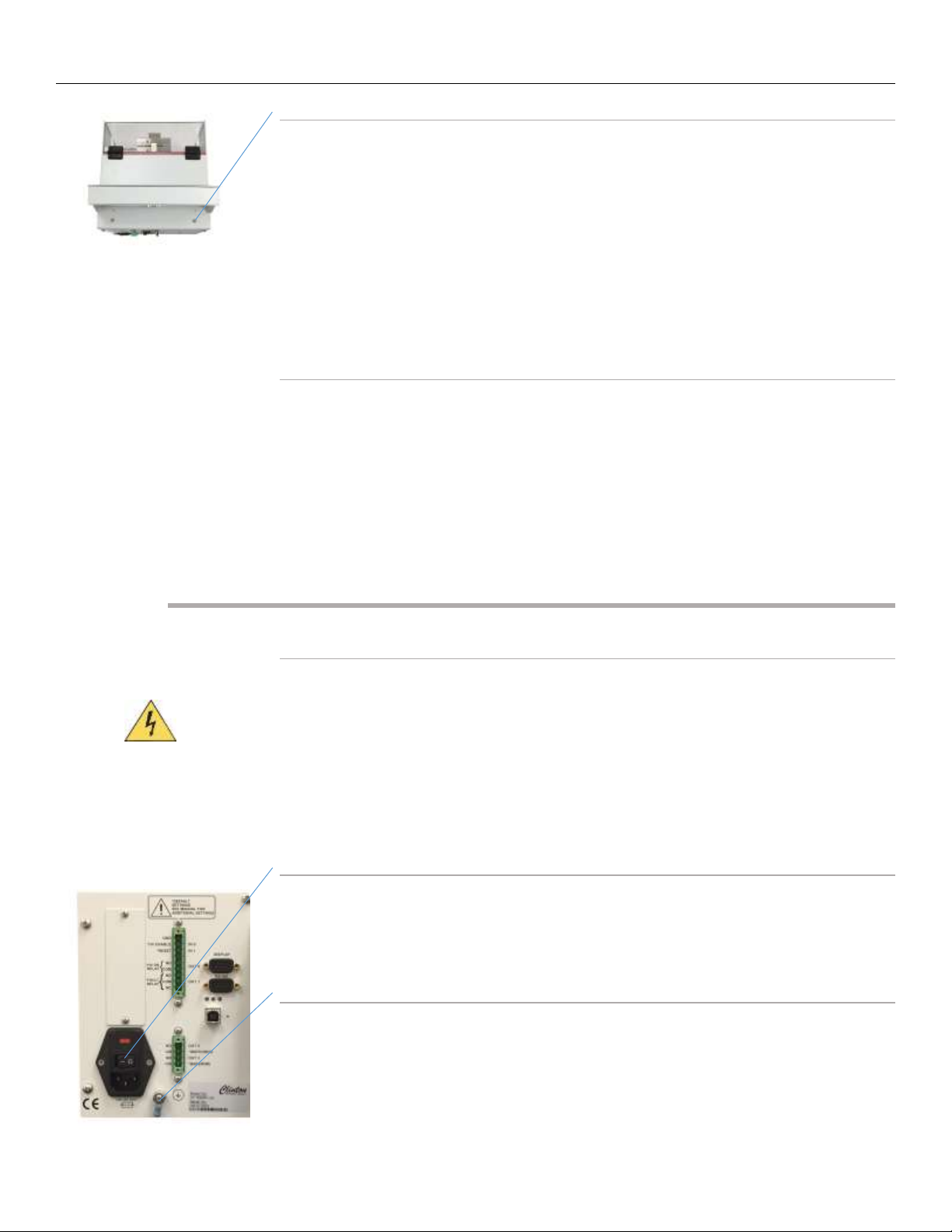
Terminal Block Wiring
Refer to the following table for information on pin functions. Locate the green
terminal blocks on the back of the spark tester and its companion green terminal
block connectors that came with the unit.
Conductors connecting auxiliary equipment, relays and switches should be
shielded 22 gauge or larger and should be stripped back ¼” (6mm) and fed into
the green terminal block connector at the proper pin number. Shields from con-
ductors connecting auxiliary equipment should be grounded to the safety ground
terminal.
Models DC-1, -10, -20B DC Spark Testers
DC-1, -10, -20B Instruction Manual –Page 15
Pin
No.
Designation Conductor
1GND
2
HV ENABLE
3
RESET
4 not used
5
NO
6
COM
7NO
8
COM
9
NC
Pin
No.
Designation Conductor
1
NO
2
COM
3
NO
4
COM
9 - Pin Terminal Block Connections
HV Enable (IN0):
CAUTION: For HV on the el ectrode, i ns tal l a norma l ly clos ed s wi tch or
rel a y conta ct** between pi ns 1&2. Thi s switch or rel a y should open
automatical l y when the wi reline s top s wi tch is a cti vated or be opened
manua lly by the s ystem operator when the li ne stops . FAILURE TO DO SO
COULD RESULT IN A FIRE HAZARD If the HV remains ON i n the el ectrode
when your li ne is s ta ti ona ry, the wire ins ulation in the electrode wil l
hea t and there is a danger of combus ti on.
External Reset (IN1):
To res et the spa rk tes ter fault rel a y wi th a n external swi tch, wire a
momenta ry s wi tch** between pi ns 1&3. When thes e conta cts clos e, the
fa ult rel a y wi l l return to a norma l sta te. The interval that the conta cts
are clos ed mus t exceed 50 ms.
(3) 22 ga. stranded
conductors rated
250V, less than 10
meters in length,
contained in a
common insulating
sheath
*When connecting auxiliary equipment to dry relay contact pins 1, 2, 3,or 4, observe maximum ratings of
120VAC at 2 amps, 240VAC at 1 amp.
4 - Pin Terminal Block Connections
Watch Dog (OUT2):
Dry rel a y contact pi ns 1&2 wil l clos e when the tes t voltage i s between
the VWDL (Voltage Wa tchdog Low Thres hol d) a nd the VWDH (Volta ge
Wa tchdog Hi gh Thres hol d) val ues .
Bare Wire (OUT3):
To activate externa l li ghts, a l a rms or rela ys* when a Bare Wire type
fa ult occurs, wire them between dry rel a y conta ct pi ns 3 & 4. If the
output function i s set LCH or RVF, the dry rel a y conta cts wi l l remai n
closed until the RESET button i s pressed or when pi ns 1&3 are cl os ed by
remote s wi tch or rel a y output function is set to NLC, the dry rel a y
conta cts will return to normal s ta te after the interval known as the
ABMS (Any Ba re Wi re Alarm Ti me) ha s ela ps ed.
(3) 22 ga. stranded
conductors rated
250V, less than 10
meters in length,
contained in a
common insulating
sheath
HV ON Indication (OUT0):
Dry rel a y contact pi ns 5&6 wil l clos e when the tes t voltage exceeds
500v. For an i ndi cation tha t HV is ON i n the e lectrode, wi re a la mp or
auxil i a ry device* here.
(3) 22 ga. stranded
conductors rated
250V, less than 10
meters in length,
contained in a
common insulating
sheath
Process Control (OUT1):
To activate externa l li ghts, ala rms or relays* when a fault occurs, wi re
them between dry rel ay contact pins 9,8 & 7. If the output functi on is se t
to LCH or RVF the dry rel a y contacts will remain cl os ed unti l the RESET
button is pressed or when pi ns 1&3 are cl os ed by remote s witch or
rel a y. If the output function is set to NLC, the dry rela y contacts wi ll
return to norma l sta te a fter the i nterva l known as the AMFS (Any Fault
Alarm Ti me) has elaps ed.
* When connecting auxiliary equipment to dry relay contact pins 5, 6, 7, 8 or 9, observe maximum ratings of
120VAC at 2 amps, 240VAC at 1 amp.
**Switches and relays connected to pins 1,2, & 3 should be suitable for 24V low current applications.

Models DC-1, -10, -20B DC Spark Testers
DC-1, -10, -20B Instruction Manual –Page 16
Connecting the Serial RS-485
The model DC-B is equipped with an RS-485 serial interface allowing the spark
tester to receive commands and exchange information with a PLC or computer.
Programming and control of voltage settings, which can be done manually on the
DC-B display, can also be done through this interface. Control display buttons can
be disabled when the serial interface is in use. See the section entitled “RS-485
Interface” for connection and communication information.
The “RS-485” interface connector is located on the rear of the DC-B directly under
the “Display” connector.
Connecting to the Analog Interface (Optional)
The model DC-B can be purchased with an optional analog interface. (Model DC-
BA) The analog interface allows the DC-B to be controlled by a PLC with standard
analog and Digital I/O. The connecting cable for this interface is not supplied by
Clinton Instrument Company. The cable composition is normally dictated by the
PLC, but ordinarily 22 gauge conductors (individually shielded or shielded pairs)
are required. The maximum length of the cable is also determined by the
equipment the DC-B is being connected to. However, it is recommended that the
cable length not exceed 10 meters.
See the section entitled “Analog Interface” for the details regarding this
interface.
Installing the CompactCom™Module (Optional)
The model DC-B can be purchased with an optional Fieldbus Communications
Interface. (Model DC-BX) This interface will allow the installation of several
fieldbus options. (DeviceNet, Ethernet IP, Modbus TCP, Profibus, Profinet)
To enable the Fieldbus Interface the proper CompactCom™ module will need to
be installed into the DC-BX spark tester.
•First remove the Anybus Slot Cover from the rear of the spark tester.
•Remove the CompactCom™module from the packaging.
•Slide the CompactCom™module into the open slot on the rear of the
spark tester.
•Secure the CompactCom™module by tightening the 2 screws.
See the section entitled “Fieldbus Interface” for the details regarding this
interface.
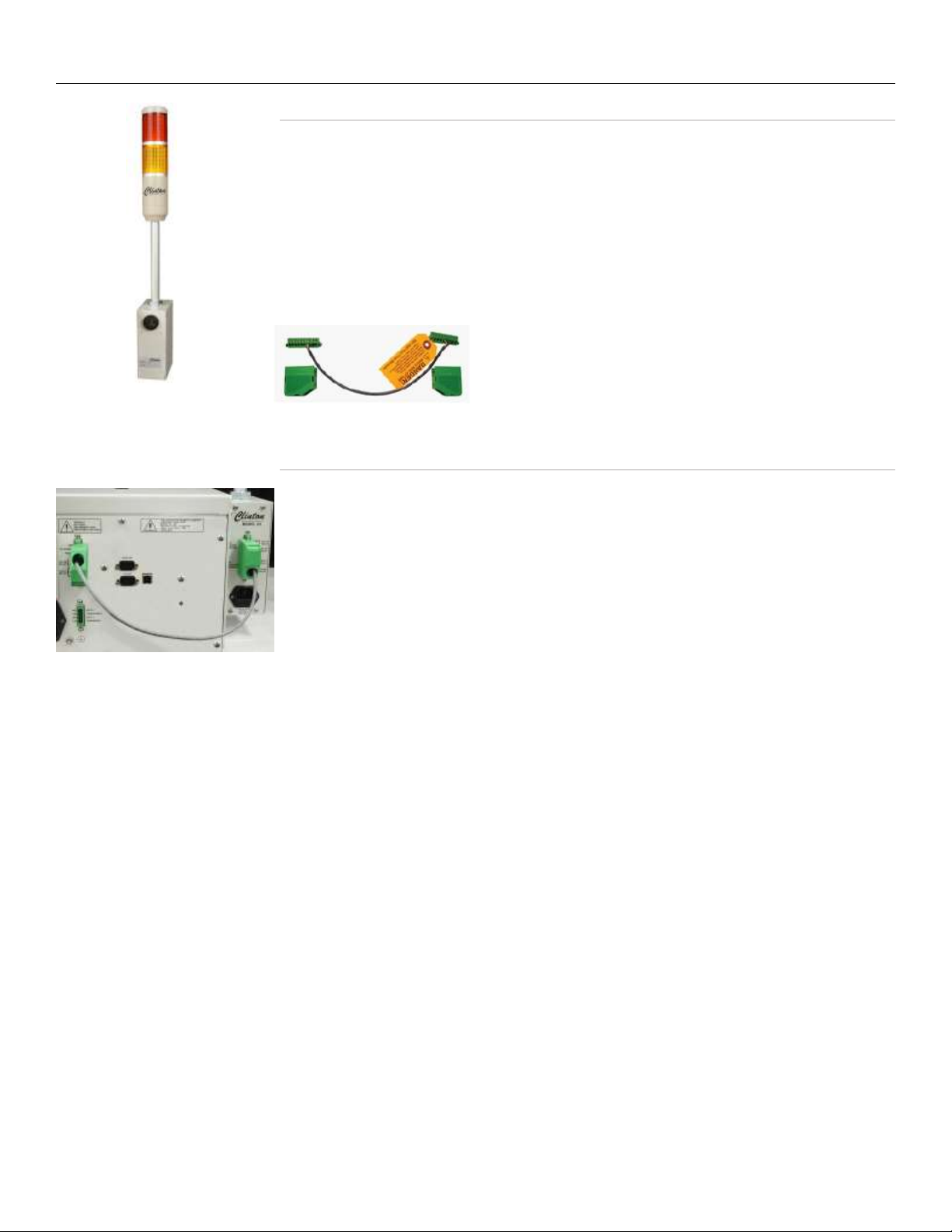
Connecting the X3B (Optional)
Models DC-1, -10, -20B DC Spark Testers
DC-1, -10, -20B Instruction Manual –Page 17
Unpacking the X3B
Remove the following items from the carton:
1. X3B Horn/Light Tower with mounting plate. Note: If the X3B was ordered
for the BD-22 electrode, the carton should contain the BD-22 mounting
plate (part #91243).
2. Power Cord (part #03780)
3. A 4 conductor cable, with a 9-pin terminal block connector on one end and
a 10-pin connector on the other. (part #91247)
Connecting the X3B
1. Decide which side of the spark tester you wish to mount the X3B. Note that
you may have to remove the small plate from the X3B chassis and secure it
to the opposite side so that the green X3B terminal block is accessible from
the spark tester back panel. Mount the X3B using the mounting plate and
the (4) bolts that attach the end guard to the spark tester, as shown in the
picture to the left.
2. Make sure the spark tester is off before wiring to the X3B.
3. Locate the 10-pin green terminal block on the back of the X3B and the 9-
pin terminal block on the back of the spark tester. The X3B is supplied with
a 4 conductor cable. The 10-pin connector will plug into the X3B terminal
block and the 9-pin connector will connect to the spark tester terminal
block. Prior to inserting them, pins 1-5 of the 10-pin connector should be
wired to accessory equipment with 22 gauge or larger, stripped back 1/4”
(6mm) and fed into the green terminal block connector at the proper pin
numbers, as described on the following page. Pins 1-3 of the 9-pin
connector should be wired as described on the following page.
4. When wiring the two units, notice that pins 5-8 on the spark tester are now
being used to communicate with the X3B. The functions of pins 5-8 on the
spark tester have now been transferred to pins 1-5 on the X3B terminal
block. When the wiring is complete, plug in the power cords to both X3B
and the spark tester.

Models DC-1, -10, -20B DC Spark Testers
DC-1, -10, -20B Instruction Manual –Page 18
X3B to Spark Tester Connections
Conductor
Terminal Block
Connections
Pin
No.
Pin
No.
Terminal Block
Connections
Conductor
COM 10 9 Not Us ed NC
COM
8 7 NO
6 5 NO
NC 5 4
COM
2
Des i gna tion
4-Conductor
Cable
Supplied
with X3B (22
ga uge or
hi gher)
NO
NO
Fault Relay
HV ON Relay
To Spark Tester:
Wi re pi ns 10-7 to
spa rk
tes ter pins 8-5 on the
spa rk
tes ter terminal block
connector
GND
(3) 22 ga.
stranded
conductors
rated 250V,
les s tha n
10 meters
in length,
conta i ned
in a
common
ins ul a ti ng
shea th
Spark Tester Terminal Block Connections
X3B Horn/Light Tower Terminal Block Connections
Not Us ed
(3) 22 ga.
stranded
conductors
rated 250V,
les s tha n
10 meters
in l ength,
conta i ned in
a common
ins ul a ti ng
shea th
Fault Relay
RESET
HV
ENABLE
8
6
Not Us ed
To X3A:
Wi re pi ns 8-5 to X3A
pi ns 10-7 on X3A termi -
na l block connector
HV ON Relay
(OUT0)
Fault Relay (OUT1)
Des i gna tion
COM
COM
4-conductor
cable
supplied
with X3A
(22 gauge or
hi gher)
9
7
**Switches and relays connected to pins 1,2, & 3
should be suitable for 24V low current
applications.
NO
22 ga .
stranded
conductors
rated 250V,
les s tha n
10 meters
in l ength,
conta i ned in
a common
ins ul a ti ng
shea th
HV ON Indicati on:
Dry rel a y conta ct pins
1&2 wi ll cl os e when
the tes t volta ge
exceeds 500v. For a n
indi ca tion that HV is
ON in the electrode,
wire a l a mp or
auxil i a ry device* here.
HV ON Relay
*When connecti ng auxi liary equi pment to dry rel a y
conta cts pins 1, 2, 3, 4, or 5, observe ma ximum ratings of
120VAC at 2 a mps or 240VAC at 1 a mp.
External Reset:
To reset the spa rk tes ter fa ul t
rel a y with a n externa l s witch,
wire a momenta ry s witch**
between pi ns 1&3. Whe n
thes e contacts cl os e, the faul t
rel a y will return to a norma l
state. The interval that the
conta cts a re clos ed must
exceed 50 ms .
HV Ena ble:
CAUTION For HV on the
electrode, ins ta l l a normal l y
closed s witch or rel a y
conta ct** between pins 1&2.
Thi s swi tch or rel ay shoul d
open automatical l y when the
wireline s top s wi tch is
acti vated or be opened
manua lly by the s ystem
operator when the l i ne stops .
FAILURE TO DO SO COULD
RESULT IN A FIRE HAZARD If
the HV remai ns ON in the
electrode when your l ine i s
stati ona ry, the wire
ins ul a ti on i n the electrode
wil l hea t a nd there is a
da nger of combustion.
COM
NO
4
3
1
3
2
1
Process Control:
To activate external
lights,alarms or relays*
when a fault occurs, wire
them between dry relay
contact pins 5,4 & 3.
If the Lch function is ON
(set on the front panel),
the dry relay contacts will
remain closed until the
RESET button is pressed or
when pins 1&3 are closed
by remote switch
or relay. If the Lch
function is OFF, the dry
relay contacts will return
to normal state after the
interval known as the
PCd (Process Control
Duration, set on the front
panel) has elapsed.
Models DC-1, -10, -20B DC Spark Testers
DC-1, -10, -20B Instruction Manual –Page 19
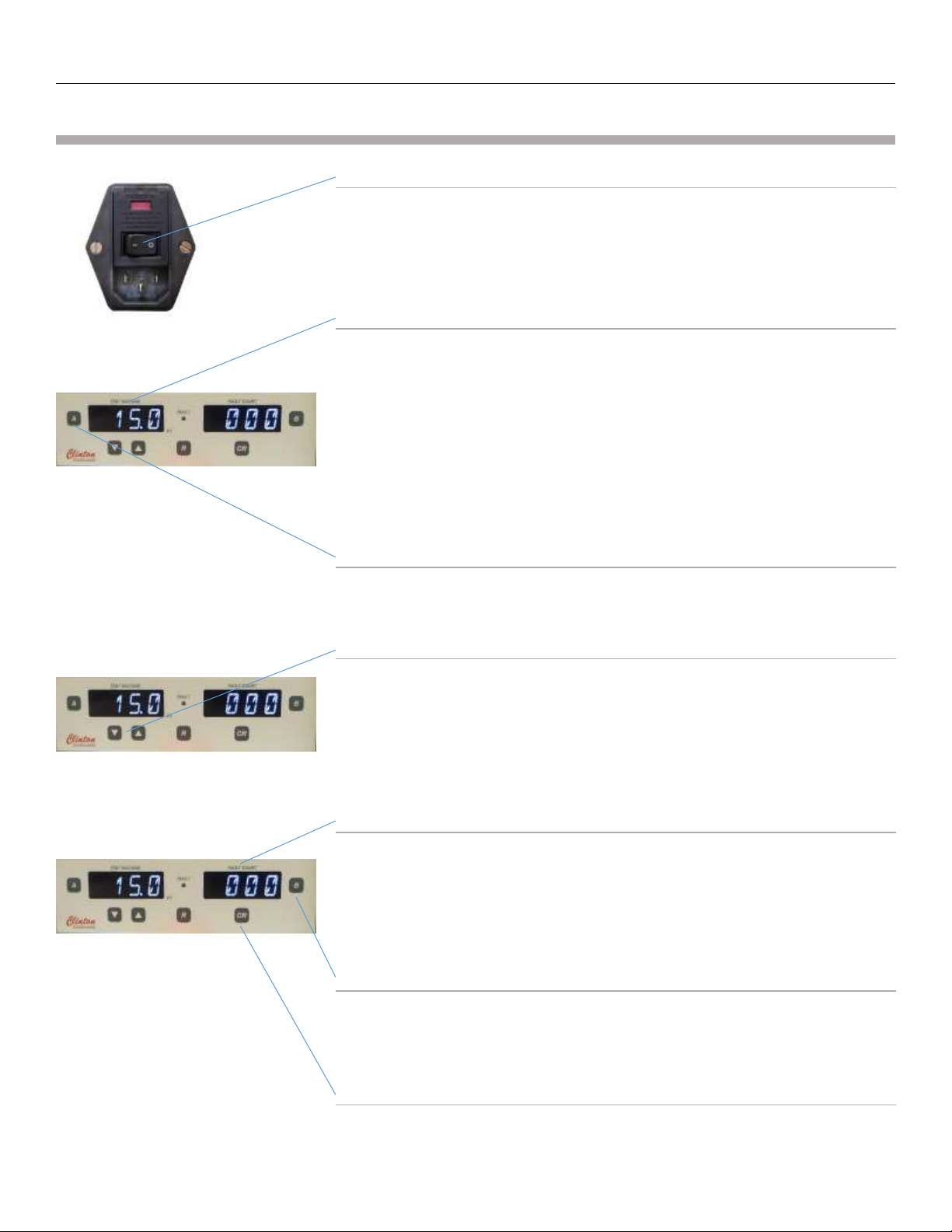
Spark Tester Controls
ON/OFF Power Switch
This switch is located on the rear panel of the spark tester.
Voltmeter
The voltmeter will indicate the high voltage present at the electrode. The
voltage is displayed in kV. When the output is set to 1,000V the display
will read 1.0. A reading of 10.2 indicates that the test voltage at the
electrode is 10.2kV DC.
This display can also display a “Percent Load” value and the “Set Point”
value by pressing the “A” Button. These values will be displayed
momentarily on the Voltmeter display and then will return to displaying
the spark tester voltage at the electrode.
“A” Button
Pressing the “A” button will momentarily cycle the Voltage display
through the “Percent Load” and the “Set Point” Values.
UP/DOWN ARROW (VOLTAGE ADJUST) buttons
The spark test voltage may be adjusted from 0 to the maximum voltage
(1,000 for the DC-1B, 10,000 for the DC-10B and 20,000 for the DC-20B)
in 100 volt increments by pressing the up and down arrow buttons under
the voltmeter. Press and hold a button to increase the speed at which
you change the voltage setting.
Fault Counter
The 3-digit fault counter registers a count each time any fault type is
detected in the electrode. This display can also momentarily show 4
additional fault counts by pressing the “B” button. These fault counts are
Pinhole, Metal Contact, Multiple pinhole, Gross Bare wire. Press the CR
button to reset the number of faults on the counter to 0.
“B” Button
Pressing the “B” button will momentarily cycle through the 4 additional
fault count values. (Pinhole, Metal Contact, Multiple Pinhole, Gross Bare
Wire)
“CR” COUNT RESET button
Pressing the “CR” button will reset all fault count values.
This manual suits for next models
2
Table of contents
Other Clinton Test Equipment manuals


