Clipper CM70 ALU User manual
CM70 ALU
OPERATING INSTRUCTIONS
Translation of the original instructions

VERS. 2018.05 CM70 ALU_MAN_EN
2

VERS. 2018.05 CM70 ALU_MAN_EN
3
The undersigned manufacturer:
SAINT - GOBAIN ABRASIVES S.A.
190, BD J.F. KENNEDY
L- 4930 BASCHARAGE
Declares that this product:
Masonry Saws: CM70 ALU 230V Code: 70184602669
is in conformity with the following Directives:
"MACHINES" 2006/42/CE
"LOW VOLTAGE" 2014/35/UE
"ÉLECTROMAGNÉTIC COMPATIBILITY" 2014/30/UE
"NOISE" 2000/14/CE
and European standard:
EN 12418 –Masonry and stone cutting-off machines –Safety
Valid for machines as of serial number : 180100000
Storage site for the technical documents :
Saint-Gobain Abrasives 190, Bd. J. F. Kennedy 4930 BASCHARAGE, LUXEMBOURG
This declaration of conformity loses its validity when the product is converted or modified
without agreement.
Bascharage, Luxembourg, 16.10.2017.
François Chianese, executive officer.
Declaration of conformity

VERS. 2018.05 CM70 ALU_MAN_EN
4

VERS. 2018.05 CM70 ALU_MAN_EN
5
CM70 ALU : OPERATING INSTRUCTIONS
TABLE OF CONTENTS
1BASIC SAFETY INSTRUCTIONS 6
1.1 Symbols 6
1.2 Machine plate 7
1.3 Safety instructions for particular operating phases 7
2MACHINE DESCRIPTION 8
2.1 Short description 8
2.2 Purpose of use 8
2.3 Layout 9
2.4 Technical Data 10
2.5 Statement regarding the vibration emission 11
2.6 Statement regarding noise emission 12
3ASSEMBLY AND COMMISSIONING 13
3.1 Tool assembly 13
3.2 Electrical connections 14
3.3 Water cooling system 15
4TRANSPORT AND STORING 15
4.1 Securing for transport 16
4.2 Transport procedure 16
4.3 Long period of inactivity 16
5OPERATING THE MACHINE 17
5.1 Site of work 17
5.2 Cutting methods 17
6MAINTENANCE AND SERVICING 19
7FAULTS: CAUSES AND CURES 21
7.1 Fault-finding procedures 21
7.2 Trouble-shooting guide 21
7.3 Circuit diagram 22
7.4 Customer service 23

VERS. 2018.05 CM70 ALU_MAN_EN
6
1 BASIC SAFETY INSTRUCTIONS
The CM70 ALU is exclusively designed for the cutting of construction products mainly on
construction sites.
Uses other than the manufacturer's instructions shall be considered as contravening the regulations.
The manufacturer shall not be held responsible for any resulting damage. Any risk shall be borne
entirely by the user. Observing the operating instructions and compliance with inspection and
servicing requirements shall also be considered as included under use in accordance with the
regulations.
1.1 Symbols
Important warnings and pieces of advice are indicated on the machine using symbols. The following
symbols are used on the machine:
Read operator’s instructions
Ear protection must be worn
Hand protection must be worn
Eye protection shall be worn
Danger: risk of cut
Rotation direction of the blade
VERS. 2018.05 CM70 ALU_MAN_EN
7
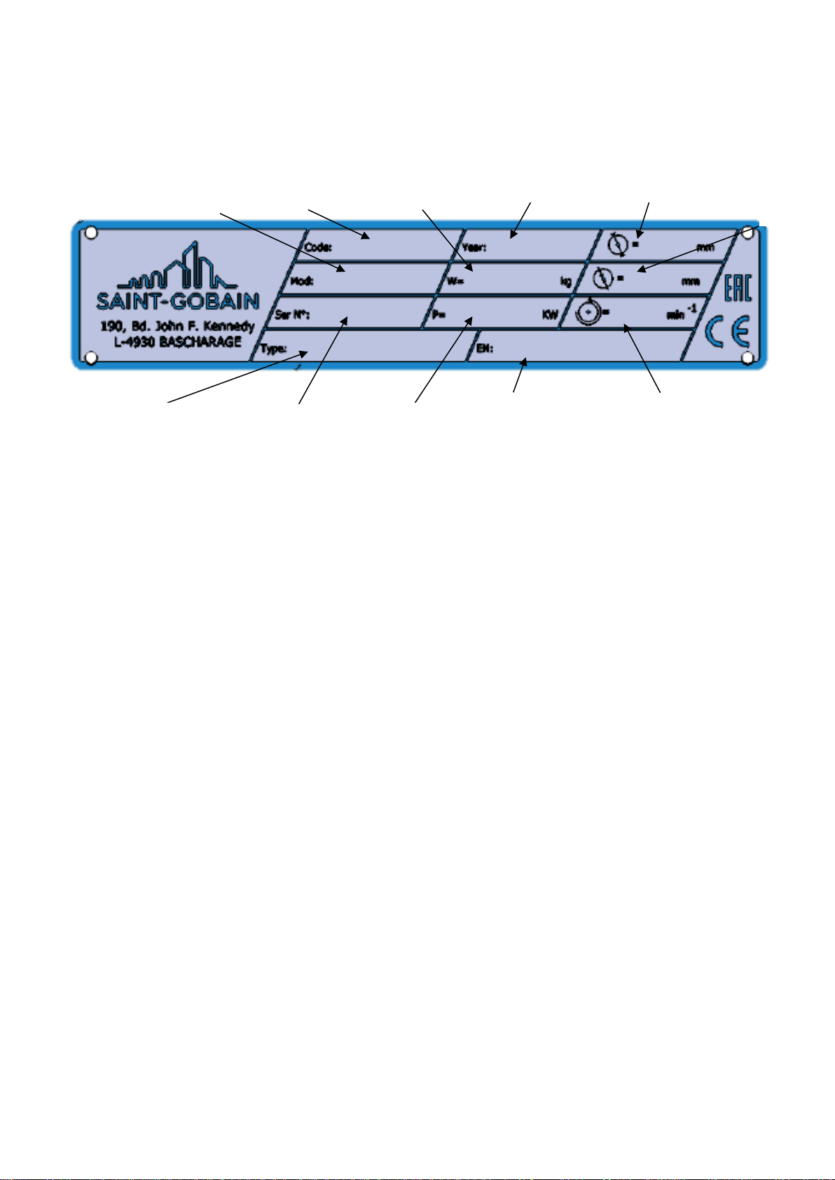
1.2 Machine plate
Important data can be found on the following plate located on the machine:
1.3 Safety instructions for particular operating phases
Before commencing work
Before commencing work, make yourself familiar with the working environment at the place of
use. The working environment includes: obstacles in the area of work and manoeuvre, the
firmness of the floor, necessary protection at the site relating to public thoroughfares and the
availability of help in the event of accidents.
Site the machine on an even, firm and stable base!
During work, apply the brakes located on two of the four wheels.
Check for correct mounting of the blade regularly.
Immediately remove damaged or badly worn blades, as they endanger the operator whilst
rotating.
The material to be cut must be held securely in place on the conveyor cart to allow no
movement during cutting operation.
Always cut with the blade guard in position.
Only fit NORTON diamond blades to the machine! The use of other tools can damage the
machine!
Read the blades’ specifications carefully to choose the correct tool for your application.
Attention is drawn to the use of BS2092 safety goggles in conformity with specified Processes
No.8 of the Protection of Eyes Regulation 1974, Regulation 2(2) Part 1.
Electrical powered machine
Always turn off the machine and separate it from the main source of electricity before any work
on the machine is done.
Make all electrical connections securely to eliminate contact of live wires with spray water or
dampness
When the machine is used with water, it is IMPERATIVE that you earth the machine properly.
In the event of the machine breaking down or stopping for no apparent reason, switch off the
main electricity supply. Only a qualified electrician is allowed to investigate the trouble and
remedy the fault.
Machine Model
Machine Code
Weight
Year of production
Maximum blade diameter
Machine type
Serial number
Power
Safety standard
Blade speed
Bore
diameter

VERS. 2018.05 CM70 ALU_MAN_EN
8
2 MACHINE DESCRIPTION
Any modification, which could lead to a change in the original characteristics of the machine, may
be done only by Saint-Gobain Abrasives who shall confirm that the machine is still in conformity with
the safety regulations.
• Raise and lower the cutting unit at different heights.
• Possible to adjust the cutting length by bringing the cutting unit closer.
• The material-holding table or cart has “U” shaped rollers that fit snugly into the slides.
• With 4 removable legs for easy transport.
• The cart is equipped with a graduated ruler that allows you to cut pieces at an angle.
• Equipped with a housing with racks for cooling the cutting blade.
• Machine protected against splashing by a curtain. Avoids the spraying of water towards
the rear of the machine.
• Electrical components comply with EU safety standards.
• The material-holding table or cart is equipped with a safety element, which prevents any
movement on the slides during transport.
• The material-holding table or cart is designed with an anti-tipping system. This device
prevents the cart from falling or tipping over when the pieces to be cut are too large or
poorly supported.
• This machine model is manufactured according to European directives.
• All motor bearings are sealed which gives them maximum service life.
2.1 Short description
The CM70 ALU block saw is designed for durability and high performance for onsite wet cutting
operations of a wide range of masonry, refractory and natural stone products.
As with all other NORTON products, the operator will immediately appreciate the attention given to
detail and quality of materials used in construction. The machine and its component parts are
assembled to high standards assuring long life and minimum maintenance.
2.2 Purpose of use
The machine is designed for cutting a large range of building and refractory materials. It is not
designed for cutting wood or metals.
VERS. 2018.05 CM70 ALU_MAN_EN
9
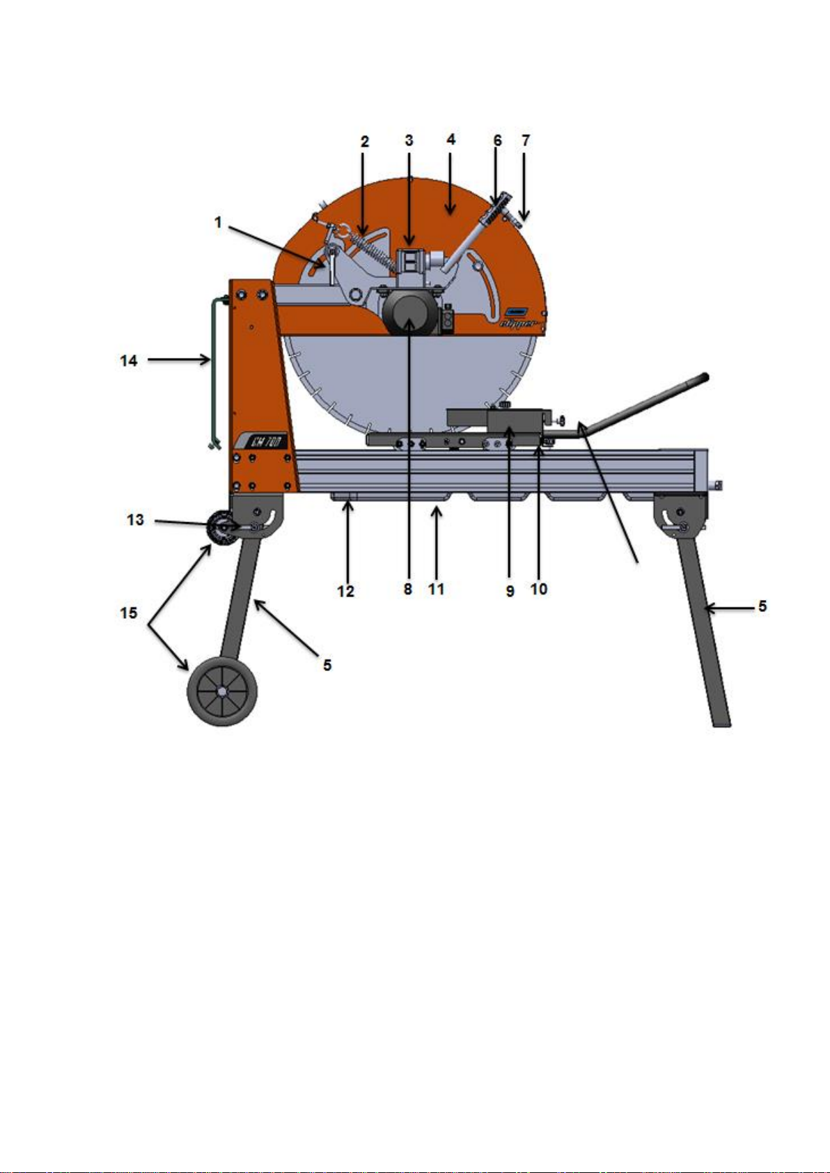
2.3 Layout
1. Quick release handle.
2. Spring.
3. Switch.
4. Blade protection.
5. Legs
6. Handle.
7. Cooling sustem.
8. Motor.
9. Block stopper.
10. Trolley
11. Water tray.
12. Chasis.
13. Leg stopper.
14. Anti splash curtain.

VERS. 2018.05 CM70 ALU_MAN_EN
10
Electrical Motor
Motor with 3 kW. Low voltage trigger (NVR) prevents the motor to restart for example after a power
cut.
The electric motor has overload protection. Thermal overload tripping can occur for two reasons:
a. tripping under light load
If connection is incorrect
If a phase is not under load
Check the connections and the phase voltage before restarting the machine.
b. tripping under heavy load
If motor has been overloaded
The ON-OFF switch also serves as emergency stop.
2.4 Technical Data
Voltage motor (V) / Phase
230 / Mono
Frequency (Hz) / Plug
50 / 3P
Kw (Hp)
3
Water tray capacity
42
Blade bore diameter (mm)
25,4
Blade diameter (mm - Pulg)
600/650/700 - 24 /25/27
Rotational Speed (Tr/min)
1500
Blade included (mm - Pulg)
Non
Maximum cutting length (mm)
540
Maximum cutting depth (mm)
Blade Ø700: 270 / 355 –
Blade Ø600: 230 / 300
Net weight (Kg)
128
Packing dimensions Lxlxh
1450 x 850 x 800
Folding legs
oui

VERS. 2018.05 CM70 ALU_MAN_EN
11
2.5 Statement regarding the vibration emission
Declared value of vibration emission following EN 12096.
Machine
Model / code
Measured value of vibration
emission at m/s2
Uncertainty K
m/s2
Tool used
Model / code
CM70 ALU
70184602669
<2.5
0.5
PRO UNIVERSAL
LASER
The vibration value is lower and does not exceed 2.5 m / s.
Values determined using the procedure described in the standard EN 12418.
The measurements are made with new machines. Actual values may vary with site conditions, in
terms of:
Materials worked
Wear Machine
Lack of maintenance
Inappropriate tool for application
Tool in poor condition
Unskilled operator
Etc…
The exposure time to vibration is based on the performance of work (related to the adequacy
Machine / Tool / worked material / operator)
When evaluating risks due to hand-arm vibration, you need to take into account effective usage at
rated power of machine during a full day of work; quite often you will realise that effective utilisation
time represents around 50% of overall duration of work. You have to consider, of course, breaks,
water feeding, preparation of work, time to move the machine, disk mounting…

VERS. 2018.05 CM70 ALU_MAN_EN
12
2.6 Statement regarding noise emission
Declared value of noise emission following EN ISO 11201 and NF EN ISO 3744.
Machine
Model / code
Sound
Pressure level
LPeq
EN ISO 11201
Uncertainty K
(Sound
Pressure level
LPeq
EN ISO 11201)
Sound power
level
LWeq
NF EN ISO 3744
Uncertainty K
(Sound power level
LWeq
NF EN ISO 3744)
CM70 ALU
70184602669
100dB(A)
2.5 dB(A)
116 dB(A)
4 dB(A)
Values determined using the procedure described in the standard EN 12418.
The measurements are made with new machines. Actual values may vary with site conditions, in
terms of:
Wear Machine
Lack of maintenance
Inappropriate tool for application
Tool in poor condition
Unskilled operator
Etc…
Measured values relate to an operator in normal use, as described in the manual position.

VERS. 2018.05 CM70 ALU_MAN_EN
13
3 ASSEMBLY AND COMMISSIONING
The machine is delivered fully equipped and assembled (although without diamond blade) and is
ready for operation after connection to the appropriate power supply.
3.1 Tool assembly
Only NORTON blades with a maximum diameter of 700 mm can be used with the CM70 ALU.
All tools used must be selected with regard to their maximum permitted cutting speed for the
machine’s maximum permitted rotation speed.
Before mounting a new blade into the machine, switch off the machine and isolate it from the main
source of electricity.
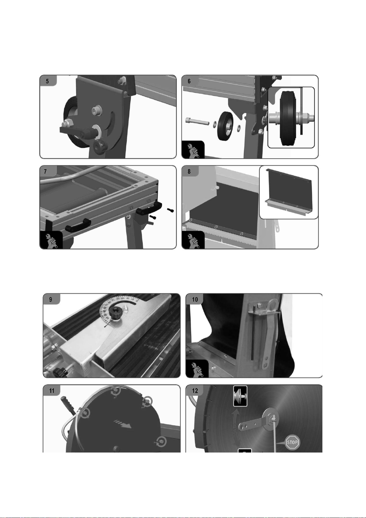
To mount a new blade, follow these steps:
1. Use the cardboard accessory to support the head while you fix it in place
2. Depending on the size of blade you will use, fix the head in one position or another.
3. Install the spring.
4. Unfold the legs and fix them in place
VERS. 2018.05 CM70 ALU_MAN_EN
14
5. Install the blocking Wheel so that the legs cannot collapse in transport.
6. Install the upper wheels.
7. Install the transport handle.
8. Install the antisplash carpet
9. Install the ruler on the cutting surface.
10.Install the tool holder.
11.Mount the blade.
CAUTION: The blade bore must exactly match the diameter of the blade shaft. A cracked or
damaged bore is dangerous for the operator and for the machine.

VERS. 2018.05 CM70 ALU_MAN_EN
15
3.2 Electrical connections
Electrical connections
The electrical equipment of the CM70 ALU cutting tables manufactured by Norton Clipper has an
IP54 protection degree. The power supply on this machine has an under-voltage coil to prevent the
machine from starting up unexpectedly. When there is a power cut or voltage drop that causes the
machine to stop, and once the normal power conditions have been re-established, the motor does
not start until the green button is pressed.
Check that,
the voltage/phase supply corresponds to the information indicated on the motor plate.
Available power supply must have ground connection in conformity with safety regulations.
The connecting cables should have at least a 2.5mm2-section per phase.
Switch on the machine
230V Motor
To start the machine, press the green button. To switch it off, press the red button.
Direction of rotation
The direction of rotation is indicated on the blade guard. If the direction of rotation does not
correspond to the direction shown by the arrow, then reverse the motor polarity by turning the phase
inverter inside the male plug with a screwdriver.
Emergency Stop
To restart the machine after an emergency stop, press green button. To stop the machine, press the
red button.
3.3 Water cooling system
Material saws are designed to work with water-cooled diamond blades. This is why one of the
essential components of its structure is the water tank that acts as a closed circuit cooling tank
(water is pumped up to the blade).
Put enough water in the tank (up to about 2.5 cm from the top edge), making sure the pump
body is fully submerged.
The blade should be sufficiently watered on both sides. You can adjust the amount of water
using the tap in the blade housing.
If the blade is not sufficiently watered, the segments may heat up, which accelerates damage
and increases the risk of blade rupture. This is why the pipes and nozzles must not be clogged.

VERS. 2018.05 CM70 ALU_MAN_EN
16
In no case should the water pump run empty. Therefore, ensure that the water level in the tank
never falls below the water suction of the pump.
If there is a risk of frost, please empty the blade cooling system completely.
During cutting operations, many impurities accumulate in the bottom of the tank. It is then
necessary to frequently change the water in order to guarantee the proper functioning of the
pump and optimal cooling of the blade. The tank is equipped with a drain plug which facilitates
this task.
4 TRANSPORT AND STORING
Take the following measures in order to transport the CM70 ALU securely.
4.1 Securing for transport
Before transporting or lifting the machine, always remove the blade and empty the water pan.
The conveyor cart must be secured:
move the conveyor cart to the end of the machine
fix it using the pin on the rear post of the chassis and the eye screw on the conveyor cart.
4.2 Transport procedure
The machine can be moved on a flat surface using its wheels. Only use the lift brackets to lift the
machine, as other parts of the machine are not designed for this purpose. The machine is not
intended to be transported by crane.
4.3 Long period of inactivity
If the machine is not going to be used for a long period, please take the following measures:
Completely clean the machine
Empty the water system
Take the water pump out of the slurry and clean it thoroughly.
The storage site must be clean, dry and at a constant temperature.

VERS. 2018.05 CM70 ALU_MAN_EN
17
5 OPERATING THE MACHINE
5.1 Site of work
5.1.1 Siting the machine
Remove from the site anything, which might hinder the working procedure!
Make sure the site is sufficiently well lit!
Observe manufacturer's conditions for connecting to power supplies!
Place electric cables in such a way that damage by the device is excluded!
Make sure you have a continual adequate view of the working area so you can intervene in the
working process at any time!
Keep other staff out of the area, so you can work securely.
5.1.2 Space required for operation and maintenance
Leave 2 m in front of the machine and 1,5 m around it for usage and maintenance of the CM70
ALU.
5.2 Cutting methods
To use the machine correctly, you must face it with one hand on the handle of the cutting head, and
the other on the handle of the conveyor cart. Always keep your hands away from the moving blade.
5.2.1 Jam or fixed cutting
In jam or fixed cutting, the cutting head is locked in a fixed position and the material is pushed into it
as shown.
Lower the cutting head to the desired cutting depth (in “through cutting”, lower cutting head until
blade periphery reaches max. 3-5mm under the surface of the conveyor cart) by means of the
handle on the blade guard
Fix position by tightening the clamping device
Put material on conveyor cart
Push the conveyor cart slowly and without undue pressure towards the rotating blade and cut
the material.
NOTE: While recommended, it is not absolutely necessary to lock the cutting head into a given
depth position when jam cutting. The desired cutting depth can be maintained by holding firmly the
depth feed handle on the blade guard.
If the full depth of cut requires excessive pressure (on very dense material e.g.) make 2 or 3 shallow
cuts.

VERS. 2018.05 CM70 ALU_MAN_EN
18
5.2.2 Multiple step cutting
Multiple step cutting consists of moving the conveyor cart with the material to be cut back and
forward under the rotating blade,
Place the material to be cut on the conveyor cart firmly against the guide-a-cut and the
backstop, keeping the hands well away from the blade.
Move conveyor cart forward near the blade and pull down the cutting head until blade is lowered
to a point where it will lightly contact the surface of the material.
Then pass the material beneath with rapid full length strokes, taking a shallow cut
(approximately 3 mm deep) on the forward. On the backward stroke, lift the blade just clear over
the cutting line.
Complete each rapid stroke backward and forward by passing the material beyond the centre of
the blade before starting the reverse movement of the conveyor cart.
NOTE: the harder the material, the more rapid should be the forward and backward strokes.
Step cutting lessens the area of the blade circumference in contact with the material, keeping the
blade cool, running free and cutting at peak efficiency.
5.2.3 General advice for the cutting
Material weighing under 30 kg and having dimensions smaller than 600x500x265mm can be cut
with the CM70 ALU.
Before commencing work make sure tools are firmly seated!
Select the right tools as recommended by the manufacturer depending on the material to be
worked, the working procedure (wet cut) to be carried out and the required efficiency.
Apply cooling water continuously whilst cutting and in good time!
When cutting work is finished, close the water-tap so you can remove the cut pieces from the
conveyor cart without getting wet.
If the thermal protection trips, wait a few minutes to allow the motor to cool down before
restarting the machine.
In case of the triggering of the thermal protection, press the black button on the switch (230V
motor) .

VERS. 2018.05 CM70 ALU_MAN_EN
19
6 MAINTENANCE AND SERVICING
To ensure a long-term quality from the cutting with the CM70 ALU, please follow the maintenance
plan below:
Begin of the day
During the changing of the tool
End of the day
Every week
After a fault
After a damage
Whole machine
Visual control (general aspect,
watertightness)
Clean
Flange and blade fixing devices
Clean
Motor cooling fans
Clean
Water pan
Clean
Water pump
Clean
Water hoses and nozzles
Clean
Water pump filter
Clean
Cart guiding bars
Clean
Motor housing
Clean
Reachable nuts and screws
Tighten up
Maintenance of the Motor
Always perform the maintenance of the motor with the machine isolated from the electrical supply.
Lubrication
The CM70 ALU uses life-lubricated bearings. Therefore, you don’t need to lubricate the machine at
all.
Cleaning of the machine
Your machine will last longer if you clean it thoroughly after each day of work, especially water
pump, water pan, motor and blade flange.

VERS. 2018.05 CM70 ALU_MAN_EN
20
The conveyor cart has an anti-tipping system so that it does not derail.
If you want to remove the cart for any maintenance operation, you should loosen the red bolt as
shown in the image. Then you must slide the anti-tipping system to extract the cart from the slides.
Table of contents
Other Clipper Saw manuals

Clipper
Clipper CM 501 HONDA User manual

Clipper
Clipper CTC701 User manual

Clipper
Clipper C13 User manual

Clipper
Clipper GC25E UP User manual

Clipper
Clipper NORTON CS1 P13 User manual

Clipper
Clipper BBC157 User manual

Clipper
Clipper TT 180 BM User manual

Clipper
Clipper C13E User manual

Clipper
Clipper C1316SS User manual

Clipper
Clipper NORTON JUMBO 651 HONDA User manual


