CLN HS-25 User manual

CLN HS-25 Manual


CLN HS-25 Manual Ver. 1 3
Important
Make sure you read and fully understand this manual before operating your
automated machine. Failure to do so will put yourself and others in harm
and will void the warranty of this equipment.

Intended Use of Machine
•Machines are designed to automatically cut nonferrous materials:
•Aluminum
•Plastic
•Brass
•Led
•Wood
•Foam
•Machines are not intended for:
•Steel
•Stone
CLN HS-25 Manual Ver. 1 4

Introduction
Everyone at CLN of South Florida, Inc. would like to
thank you for purchasing the CLN Brand CNC Router
machine. We understand that you had a choice and
you picked ours. Before you get started, there are a
few things that we need to go over.
CLN HS-25 Manual Ver. 1 5
Purpose of this publication
•To help guide you through the learning curve of
setting up and operating a new piece of automated
equipment.
•As a training aid.
Contents
This manual will take on average about an hour to read
and doing so will help you to better understand the
machine functions and operations.
Disclaimer
CLN of South Florida, Inc. makes every effort to provide
their valued customers with current and accurate
information about their equipment. However due to
constant research and development and an
unsurpassed passion to provide our customers with the
latest in cutting edge technologies, we cannot guarantee
that the contents of this manual are current and
complete.
Copyright
This manual contains information that is copyright
protected. All rights are reserved. No part of this manual
may be repurposed or reused without consent from CLN
of South Florida, Inc.


Safety
Your Responsibilities:
•As an operator of the CLN machine, you are responsible to follow all safety procedures. Any person who operates or does any
maintenance on this machine must be aware of all safety procedures.
CLN HS-25 Manual Ver. 1 7
Safety Precautions:
•Do not wear any loose-fitting clothing such as scarves or hanging jewelry.
•Do not put hands in or on any moving parts at any time.
•Do not operate machinery while under the influence of alcohol, drugs or any other substance that may impair
or alter your judgment.
•Always wear gloves when handling sharp materials.
•Always wear eye and hearing protection when operating equipment.
•Do not operate the machine without all the covers in place.
•Keep hands, head and body out of the way of moving parts.
•When performing maintenance work on the machine always unplug the incoming electric power and
disconnect the compressed air supply. Make sure the air is completely drained out of the system.
•Be sure to stay clear of moving parts when turning on the air supply, the tools may unexpectedly move
during the initial connection.
•Never leave the machine unattended.
•Completely power down when not in use.

CLN HS-25 Manual Ver. 1 8
•When servicing the machine, you must first disconnect the electricity, disconnect the compressed air line and completely drain the air
out of the system. If you do not disconnect the electric power and the compressed air line and drain the system, you will put
yourself at serious risk of causing permanent damage to yourself or death.
Servicing the Machine:
Guidelines:
•Always follow the safety rules. Under no circumstance should equipment be used for anything other than what it is designed for. Any
person who operates or does maintenance on this equipment should be aware of all safety and operating procedures. It is extremely
important that this equipment is handled with care! Distractions such as horseplay, carelessness, loud noises and sudden
movements can result in unsafe conditions, therefore, should be always avoided when operating equipment.
Environmental Considerations:
•Climate Control
•The machine should be in a climate-controlled area and NOT exposed to extreme temperatures and or weather.
•There are components on the machine that are susceptible to corrosion and should NOT be exposed to any water based
lubricant fluid or humidity.
•Clean Working Conditions
•Your machine should be located in a clean environment.
•Keep your machine and work area free of dirt and debris.
•Lighting
•Your machine should be operated in a well lighted area.

CLN HS-25 Manual Ver. 1 9
Caution Labels:
Emergency Stop:
This machine is equipped with 3 emergency stops, two
are located on the gantry and the other located next to
the monitor. Pressing it will halt all motion on the
machine as well as bleeding all the compressed air
from the machine's pneumatic cylinders. The machines
computer and monitor are the only two components that
will remain on with the emergency stop pressed.
Danger Stay clear sticker: Means that
the machine moves automatically and will
move without warning and cause serious
damage to anyone that puts any of there
body parts in the area.
Warning sticker: Means that the area
around the sticker moves automatically and
will move without warning and cause
serious damage to anyone that puts any of
there body parts in the area.
Danger Hazardous Voltage sticker:
Means that the area around the sticker can
cause an electrical shock to anyone that
puts any of there body parts in the area.


CLN HS-25 Manual Ver. 1 11
Components Overview:
The HS-25 CNC Router can be configured a few different ways.
Bed type:
Phenolic or T-Slot.
T-Slot Vacuum or T-Slot Clamps
Tool Changer
Manual (MTC) or Automatic Tool Change (ATC).
Automatic Tool Change
Carousel or Rack tool forks.
This manual covers all the possible configurations.

CLN HS-25 Manual Ver. 1 12
Components Overview:
Table Size
4 X 8 and 5 X 10
For drawing purposes
The machine is shown
without covers.

CLN HS-25 Manual Ver. 1 1313
Components Overview Continued:
Table Size
6 X 12
For drawing purposes
The machine is shown
without covers.

CLN HS-25 Manual Ver. 1 1414
Components Overview Continued:
Machine Bed:
•CLN offers two basic types of machine beds. A
Phenolic Bed and a T-Slot Bed.
Phenolic Bed
•The Phenolic Bed is a resin-based product that is
machined into 1.25-inch squares. The squares allow
the vacuum pump to pull air around the squares
evenly. A MDF board is placed on top of the phenolic
then the material that you want to cut is placed on top
of the MDF. The pump will pull air through the MDF
which will hold the material that you wan to cut, firmly
to the MDF.

CLN HS-25 Manual Ver. 1 1515
Components Overview Continued:
Machine Bed Continued:
T-Slot Bed
•A T-Slot Bed is constructed of structural aluminum. A
PVC sheet is laminated to the aluminum. The Slots are
on 6.125” centers and run all the way down the length
of the table.
•There are two ways to hold the material down on a T-
Slot table.
Clamping
•Tee Slot Nuts and bolts along with clamp bars are
used to clamp the material to the machine bed.
Vacuum
•Machines that have T-Slot Beds can also have a
vacuum system added to them. Each section is hollow,
and a series of holes are drilled into the bed of the
machine. A Sheet of MDF can be placed on top of the
T-Slot and the vacuum pump will pull a vacuum
through the MDF and hold the material down firmly

Spindle
•The (ATC) Automatic Tool Changing Spindle, spins
the router bits at a high RPM. The ATC Spindle is
equipped with an electric cooling fan. CLN can also
add a dust boot that automatically drops down when
the spindle is turned on as shown here.
CLN HS-25 Manual Ver. 1 16
Components Overview Continued:
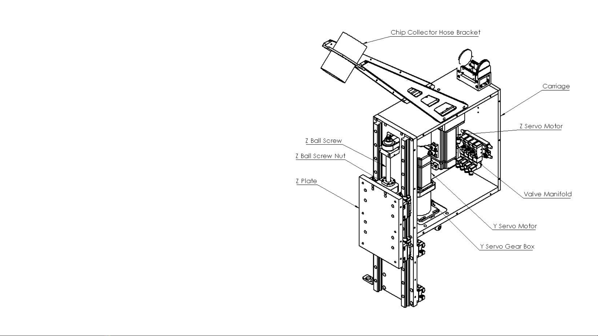
Carriage Assembly
•The Carriage is designed to move the spindle in
the Y and Z direction on the machine. This is
where the motors for Y and Z are located. The
air valves are also located inside. The Spindle
mounts to the Z plate that is mounted to the front
of the carriage.
CLN HS-25 Manual Ver. 1 17
Components Overview Continued:

Homing Cell
•This is a Proximity Sensor located in serval places on the machine. It
senses the steel or aluminum as it moves past the sensor. When the
material is in front of the sensor a red LED light will illuminate.
Tool Changing Carousel
•The tool changing carousel has 10 tool forks that will hold 10 tool holders.
This unit mounts to the left side of the gantry. The when the machine
performs a tool change, the tool forks rotate around for the spindle to either
load or unload a tool holder. An added feature of the carousel tool changer
is that a tool presents sensor prevents the operator from putting a tool in the
wrong spot causing a crash or loading a tool on top of an existing tool.
CLN HS-25 Manual Ver. 1 18
Components Overview Continued:

Tool Calibration Switch
•This unit is usually mounted on the front right side of the machine.
The tool calibration switch is used to calibrate your tools that are
either stored in the tool changer for a (ATC) machine or for a (MTC)
machine the current tool that is in the spindle. When installing a new
tool in the machine you will have to calibrate the tool only once. The
machine will bring the tool over to the button then slowly lower the
tool down until it touches the top of the button.
Vertical Support
•The vertical support bolts to the gantry. This is what moves the
spindle in the X direction. There will be 2 on the machine. The one
on the right side is called X1, the one on the left side is called X2. A
servo motor is attached to a planetary gear box that has a pinion
gear attached to the gear box shaft. The adjustment jack bolt is
used to adjust the pinion gear into the rack that is mounted on the
machine.
CLN HS-25 Manual Ver. 1 19
Components Overview Continued:

Rack Tool Changer
•A Rack Tool Changer holds a series of tools along the rear
of the machine. The spindle moves the tool holders in and
out of the tool forks that are mounted along the rail.
CLN HS-25 Manual Ver. 1 20
Components Overview Continued:
Table of contents


