-
2
-
2. GENERAL DESCRIPTION OF ENGINE COMPONENTS
2-1 CYLINDER AND CRANKCASE
The cylinder and crankcase are aluminum die-casting
as a single piece. A special cast iron cylinder liner is
molded into the aluminum die-casting.
The crankcase has a mounting surface on the output
shaft side to which the main bearing cover is attached.
The cylinder is inclined to the right at an angle of 25
degrees from the horizontal as viewed from the output
shaft side.
2-2 MAIN BEARING COVER
The main bearing cover is an aluminum die-casting,
which is mounted on the output shaft side of the
crankcase. By removing the main bearing cover,
the
inside of the engine can be inspected with ease.
Pilots and bosses are machined into the cover
to facilitate the direct coupling of the engine with
machines such as generators and pumps.
Oil gauges (fillers) are on both sides of the cover for
easy maintenance.
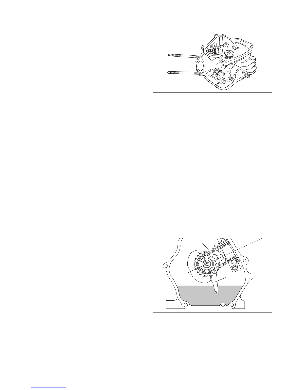
2-3 CRANKSHAFT
The crankshaft is forged carbon steel, and the crank
pin is high-frequency inductionhardened.
The crank sprocket used to drive the chain and the
gear used to drive the governor gear are pressed into
the output end of the shaft.
2-4 CONNECTING ROD AND PISTON
The connecting rod is a specially heat-treated
aluminum alloy die-casting. Its large and small ends
function as bearings. A splasher built into the
connecting rod lubricates by splashing engine oil.
The piston is an aluminum alloy casting with grooves
for mounting one compression ring and one oil ring.
Fig.2-1
Fig.2-2
Fig.2-3
25°
Fig.2-4