7.2-TMC5020P00
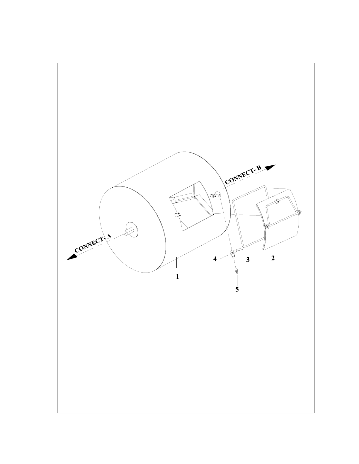
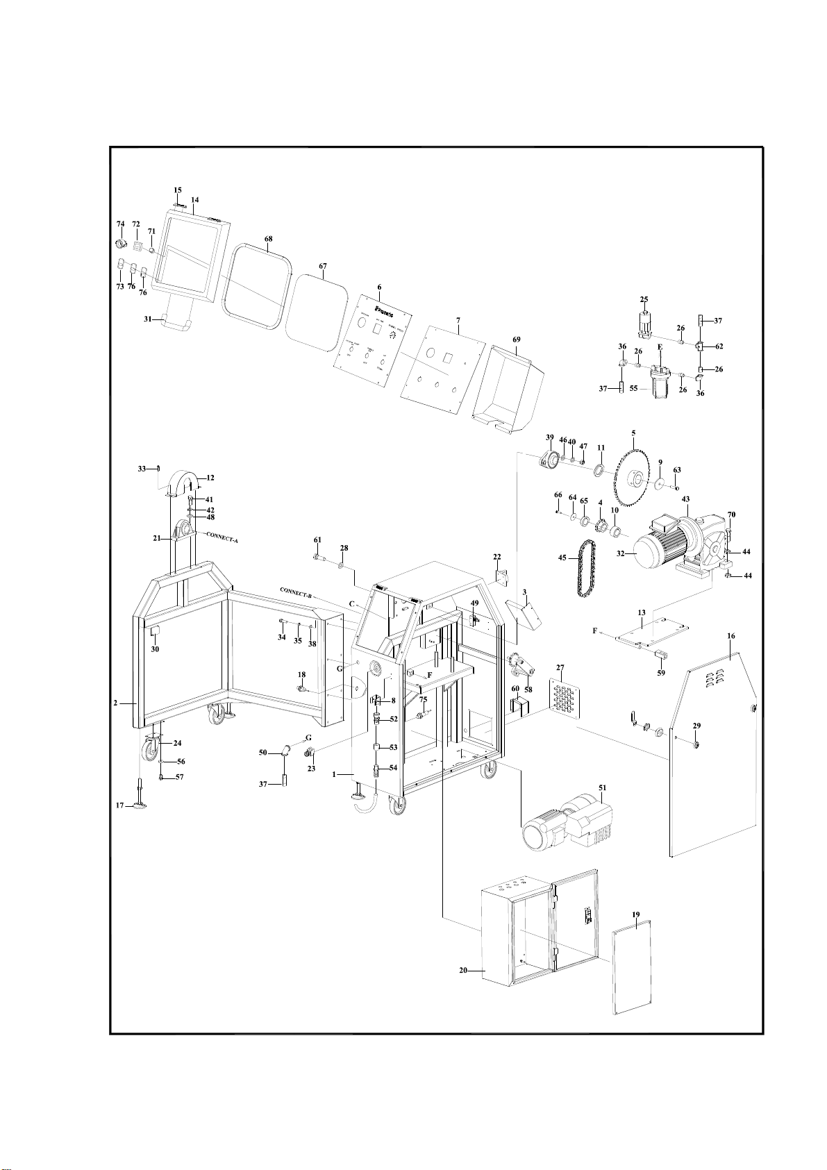
NO. PART NO. DESCRIPTION QTY NOTES
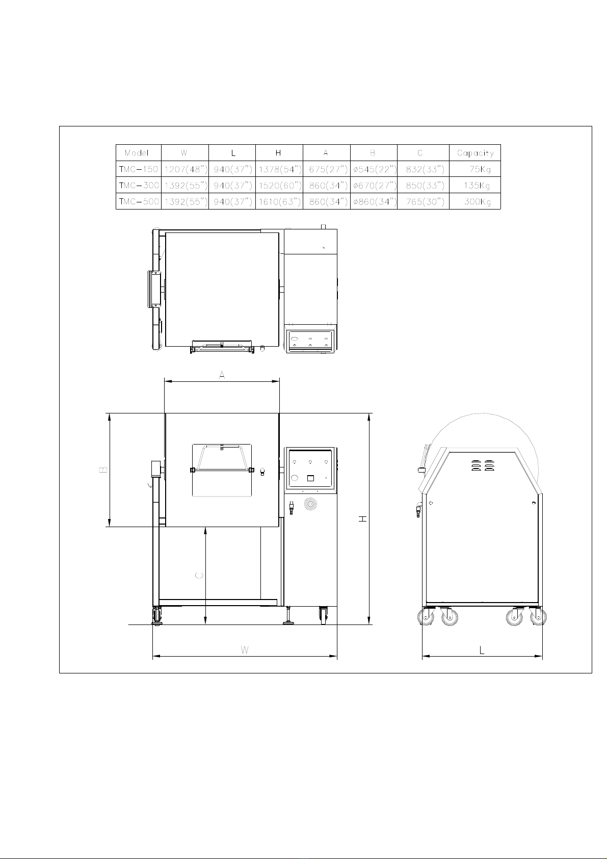
MC15101000 Frame(TMC150)
MC50101002 Frame(TMC300,TMC500) 1
MC15102000 Side frame(TMC150) 1
MC50102000 Side frame(TMC300.TMC500) 1
3 TM5H116000 Electrical protect plate 1
4 MC50106001 Chain wheel 1
5 MC50107000 Chain wheel 1
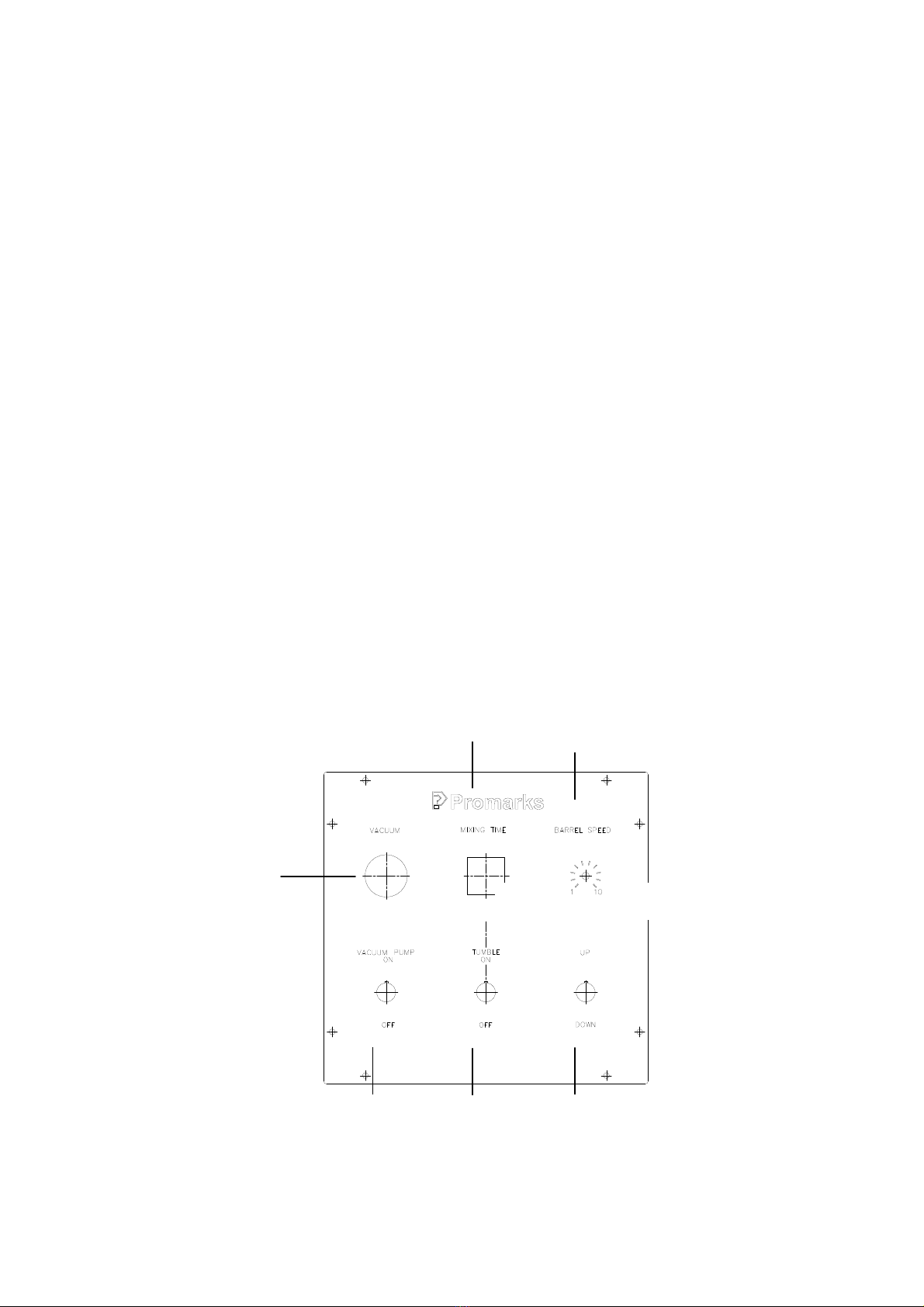
6 MC50109001 Control panel plate 1
7 MC50110001 Control panel bottom plate 1
8 MC50111001 Fixed plate 1
9 MC50118000 Pad 1
10 MC50113000 Reduction sleeve 1
11 MC50116000 Reduction sleeve 1
12 TM3H139000 Cover plate 1
13 MC50122001 Motor fixed plate 1
OPTION2
OPTION1
14 TM3H130011 Control panel cover plate 1
15 D2320020 Hinge 2
16 TM3H190000 Side door 1
17 2712222 Base leg 4
18 2850608 Sensor 1
19 TM3H803000 Panel 1
20 TM3H801000 Electrical box 1
21 2728537 Bearing pillow blockUCP209 1
22 28017051 Switch 1
23 2870074 Switch M22EL-TSF20E30 1
24 27121411 Casters 4" 4
25 29118085 Valve VXZ2242-04-BGR1(AC24V) 1
26 290932570 Nipple 1/2"x30 3
27 TM3H145000 Cover plate 2
28 2705329 Flat washer M16 2
29 2883349 Door lock C408K 2
30 28501030 Reflector 1
31 2883343 Hinge 1
8