CM Promax SC-800 User manual

SC-800
Single Chamber Vacuum Packaging
Machine
Operation Manual
Version 6.9.1
1915 E. Acacia Street, Ontario, CA91761, U.S.A
TEL : 1-909-923-3888
FAX : 1-909-923-3588
http://www.promarksvac.com
S/N: QCSIGNATURE:

TABLE OF CONTENTS
1. SAFETY ................................................................................................................... 1
1.1 SAFETY RECOMMENDATIONS ............................................................................... 1
1.2 PERSONALSAFETY .................................................................................................... 2
1.3 FOOD SAFETY ............................................................................................................ 3
2. INSTALLATION..................................................................................................... 4
2.1 UNPACKING .................................................................................................................. 4
2.2 MOVINGTHE MACHINE ........................................................................................... 4
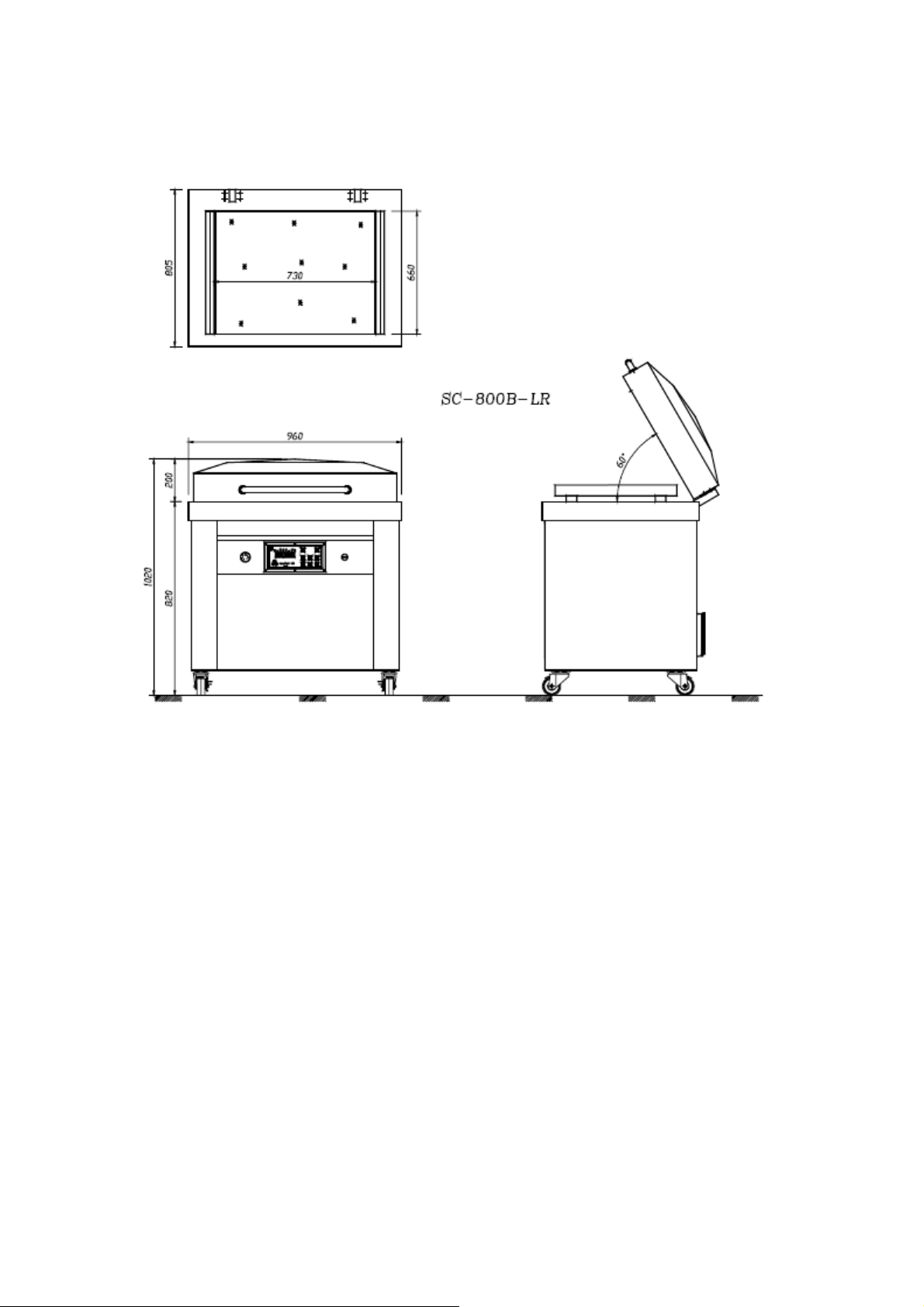
2.3 MACHINE
SPECIFICATI
ONS ..................................................................................... 5
2.4 ENVIRONMENT REQUIREMENTS .......................................................................... 5
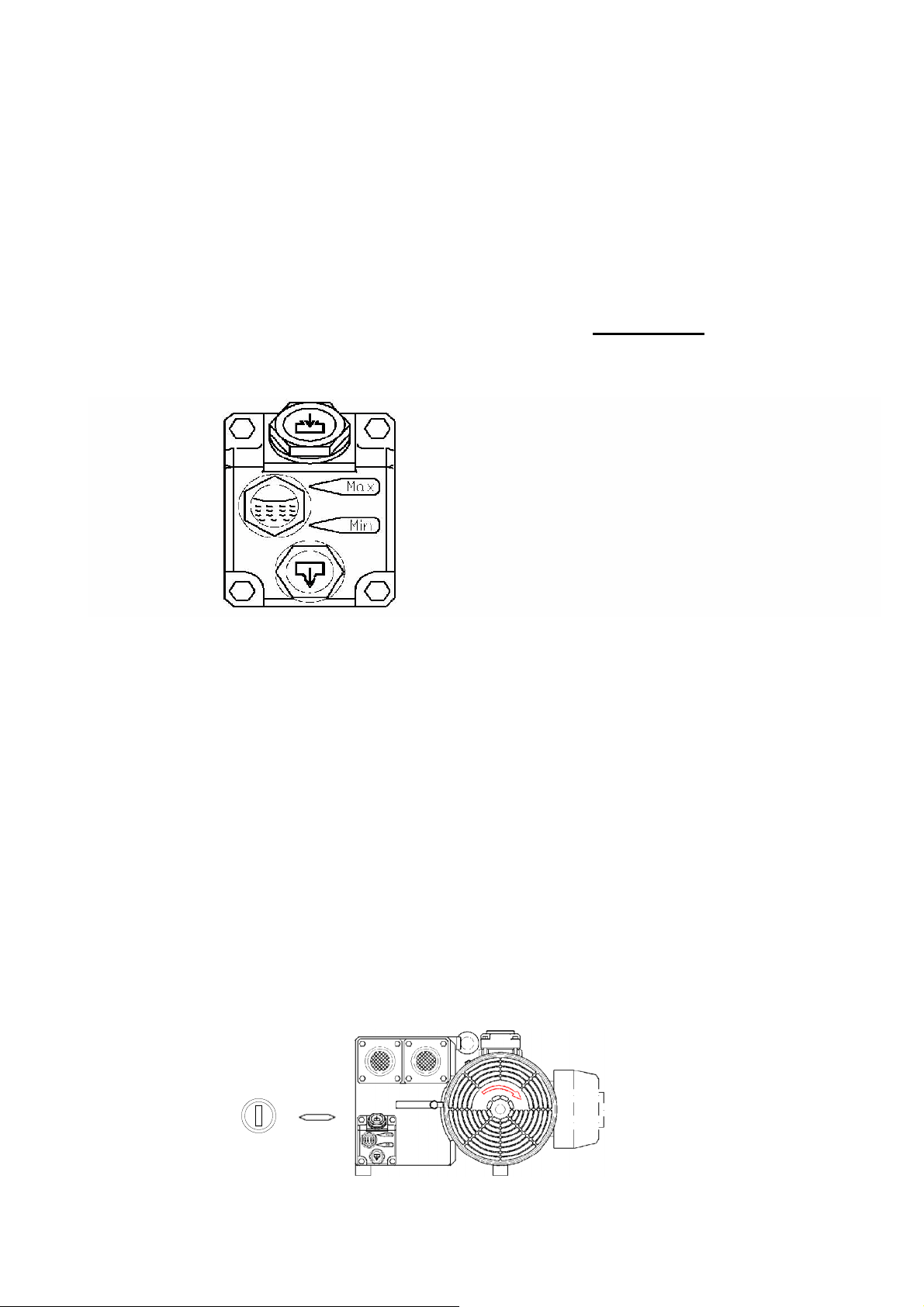
2.5 CHECK OIL LEVEL ..................................................................................................... 6
2.6 POWER CONNECTION ............................................................................................... 6
2.7 VACUUM PUMPROTATION ...................................................................................... 6
3. OPERATION........................................................................................................... 7
3.1 VACUUM SETTING GUIDELINES ............................................................................ 7
3.2 BASIC OPERATING INSTRUCTIONS ...................................................................... 7
3.3 OPTIONALDEVICE ..................................................................................................... 7
3.3.1 GAS FLUSHING UNIT ....................................................................................... 7
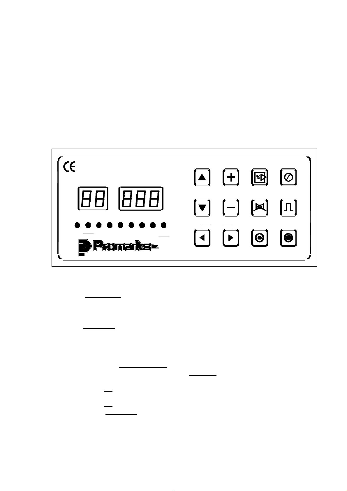
3.4 OPERATION OF THE PNC-01 DIGITALCONTROLPANEL ............................... 8
3.4.1 STANDARD MACHINE – BASIC INSTRUCTIONS ..................................... 8-9
3.4.2 SETTINGTHE PARAMETERS FOR THE OPTIONAL SETTINGS............ 10-12
4. MAINTENANCE .................................................................................................... 13
4.1 BASIC MAINTENANCE ............................................................................................. 13
4.1.1 DAILYVISUAL INSPECTION ......................................................................... 13
4.1.2 DAILY CLEANING ............................................................................................. 14
4.2 VACUUM PUMPMAINTENANCE ............................................................................. 14
4.3 SEALBAR MAINTENANCE ....................................................................................... 14
4.4 VACUUM VALVE MAINTENANCE ......................................................................... 17
5. TROUBLESHOOTING ........................................................................................ 18
5.1 OPTIONAL DEVICE ..................................................................................................... 18
5.2 25 PIN D TYPE TERMINALWIRING CONNECTION INSTRUCTIONS ............ 19
5.3 PNEUMATIC DIAGRAM ............................................................................................. 20
5.4 ELECTRICALDIAGRAM ........................................................................................... 21
6. FABRICATION ..................................................................................................... 22
6.1 BODY DIAGRAM ........................................................................................................ 23-24
6.2 WORKING BED ............................................................................................................. 25
6.2.1 WORKING BED(LR) .......................................................................................... 25-28
6.2.2 WORKING BED(FB) .......................................................................................... 29-32
6.3 LID DIAGRAM ............................................................................................................... 33
6.3.1 LID DIAGRAM(LR) ........................................................................................... 33-34
6.3.2 LID DIAGRAM(FB) ............................................................................................ 35-36
6.4 SEALING BAR-STANDARD DIAGRAM ................................................................... 37-40
6.5 ELECTRICAL BOX ....................................................................................................... 41

1
1.SAFETY
1.1SAFETY RECOMENDATIONS
Unsafe practices or unauthorized modifications of machine could result in accidents or property
damage.
For safe installation, operation, handling and maintenance, please strictly follow the simple safety
rules stated below and take precautions. Failure to follow these safety rules and take necessary
precautions can result in serious injury or death as well as cause damage to the equipment.
1) Never operate or service your Promax / Promarks machine until you have read this manual
completely and understand it fully.
2) All adjustments and repairs must be carried out only by qualified technicians or maintenance
personnel.
3) No service work should be attempted until the machine’s power has been turned off.
All proper lock out / tag out procedures should be followed.
4) Do not put tools, parts or other foreign objects on or into the machine.
5) Always keep the machine clean, lubricated and in good working condition.
6) To provide protection against the risk of electrical shock the power connection must be
properly grounded at all times.
7) The machine should always be operated on a flat stable surface.
8) A certified electrician should be employed to install the permanent electrical
connections for your new machine.

2
1.2PERSONALSAFETY
Please read and understand this operation manual before using this equipment. Failure to
follow the operating instructions may result in personal injury or damage to the machine.
The following procedures and guidelines must be observed to avoid problems that can result in
property damage, personal injury or death. If you have any questions regarding this information
please contact Promax /Promarks, Inc. Service Department at (909) 481-3338.
Hazardous Voltage:DANGER
Electrical power must be disconnected and locked out before servicing or cleaning of the machine.
Do not remove any panels before power has been disconnected and locked out due to the risk of
electric shock hazard.
Explosion Hazard: DANGER
When utilizing the gas flush feature (optional) do not use any gas mixture with greater than 22%
oxygen content.
Blade Hazard: WARNING
If your machine is equipped with either a Perforating Knife System (optional) or a Precut Knife
System (optional) then do not remove or install blades without wearing protective gloves. These
blades are SHARP, use care when handling.
Signal words used in classifying potential hazards are defined as follows:
DANGER: Indicates an imminently hazardous situation, which if not avoided, may result
in death or serious injury.
WARNING: Indicates a potentially hazardous situation, which if not avoided, could result
in serious injury.
CAUTION: Indicates a potentially hazardous situation, which, if not avoided, may result
in minor to moderate injury. Caution also indicates actions that may cause property
damage.

3
1.3FOOD SAFETY
While many Promax / Promarks machines are used in applications involving vacuum packaging
and vacuum cooking, there are inherent risks associated with these techniques that can result in
serious illness or death to the consumer of the food product. Therefore if you are using
your machine for food applications, you must consult a qualified food technician or specialist
in vacuum / modified atmosphere (M.A.P.) to review the safety of your application.
GAS FLUSH
If your machine is equipped with gas flush (optional) and your application involves the use of
gas flush to extend the shelf life of your product you must consult a qualified food technician or
specialist to review your application and develop a suitable gas mixture for your package.
Further you must perform quality control and gas analysis on your final M.A.P. package.
CLEANING
Every environment and application is different; therefore Promax / Promarks cannot provide
cleaning procedure instructions that will guarantee microbiological sanitation. Therefore Promax /
Promarks recommends that the purchaser of these machines consult with a sanitation expert to
review your procedures for cleaning the machine while operating in your environment and with
your specific product to develop a robust cleaning schedule and methodology,followed by
bacterial testing to ensure satisfactory cleaning is achieved.

4
2.INSTALLATION
2.1
UNPACKING
Carefully remove the cardboard outer shell by cutting the retaining straps then removing
the top and then the side panels.
Inspect the machine carefully for any hidden shipping damage. Notify the shipping
company right away if any damage is observed.
Remove the machine from the wooden skid. This can be done by two people on the
smaller table top machines. However an approved fork lift will be required for the larger
SC and DC models. Important note: Refer to the Moving the Machine Section below.
Wipe down the outside of the machine.
2.2 MOVINGTHE MACHINE
Promax chamber style vacuum packaging machines are available in three basic designs, TC
(Table Top), SC (Free Standing Single Chamber) and DC (Double Chamber). Recommendations
for the movement of all three types are listed below.
TC Machines: Some of the smallest TC units may be lifted off of their wooden skid and moved
manually. However Promax recommends that moving even the smallest of their TC units
should not be attempted by one person. The larger TC units should be lifted with the aid of a
fork lift or other approved lifting aid. Prior to lifting with a forklift the forks should be adjusted to
a width that provides the machine with stable support. The proper lifting point for TC machines is
to place the
forks so they come in contact with the units rubber feet located on the bottom of the
machine.
SC Machines: All SC units should be lifted from their wooden skid and moved to the location
where they will be used with an approved fork lift. Be sure to take note of the points listed below.
DCMachines: All DC units should be lifted from their wooden skid and moved to the location
where they will be used with an approved fork lift. Be sure to take note of the points listed below.
* Make sure the fork lift forks are properly adjusted for width and use fork extensions if needed.
*Make sure to ascertain the center of gravity and use identified lifting points.

5
2.3 SC-800 SPECIFICATION
2.4ENVIRONMENT
EQUIREMENTS
The machine will be difficult to start ifthe air temperature is very low. This is caused by the
increase in the vacuum pump’s oil viscosity due to the low temperature. To prevent this, please set
up machine according to the installation checklist described as below:
zTemperature: around 5 ~ 40℃
zWorking elevation: between 0 ~ 1000 meters
zRelative humidity: 30 ~ 95% RH
zDuring operating, heat is generated by the vacuum pump and vacuum process, so a
machine temperature of around 70 ~ 80℃ is normal. The machine must have free air
access for cooling.
zA minimum distance from walls, other machines, etc. should be maintained, at least 20 cm for
each side of machine for providing adequate ventilation.

6
2.5CHECK OIL LEVEL
Check the oil level only when the machine is not in operation and all
vacuum built up in the chamber has been vented. Be aware that the oil
may be very hot and avoid all contact.
Checking the Oil Level
*
Check the oil level on a daily basis
*
When checking the oil level use the sight gauge shown in figure 1 below. The level
should be between the arrows indicating Minimum and Maximum. If the level is below the
minimum arrow add oil until the maximum arrow is reached.
Figure 1
2.6 POWERCONNECTION
When preparing to install the machine’s main power connection please refer to the electrical
information on the serial number plate located on the machine’s back panel. A certified
electrician should be employed to complete this connection.
2.7 VACUUM PUMP ROTATION
If your machine operates on 3 phase power it is important to check the rotation of the vacuum
pump. The pump should turn in the direction indicated in Figure 2 below. If the pump turns
in the wrong direction it will make a sound that is obviously wrong. Turn off the power
immediately and change the position of two of the power wires and retest.
Figure 2
Main switch

7
3. OPERATION
3.1 VACUUM SETTING GUILDLINES
Pr
odu
c
ts
Vacuum time/Sec. Storage life when stored
at
2~ 6
℃
/
day
Fresh meat
30
10
Pork
30
10
Bee
f
30
30
Meat with liquid 15~
30
14
P
a
s
ta 3~
9
21
Sliced sausage
15
10
Cold cut
s
9
10~
21
3.2BASIC OPERATING INSTRUCTIONS
Turn on the main switch and the LED display shows the operation menu, at this
time, machine is ready to operate.
Place the product to be packaged in a vacuum pouch. Place the bag in chamber with
the open end of bag across the sealing bar. (With a package that doesn’t completely
fill the chamber, place provided flat plates in the chamber to shorten vacuum time.)
Close the lid to start the cycle, the lid will open automatically when cycle is
completed.
Take out the sealed product from vacuum chamber.You are ready to start the next
cycle.
After all packaging is completed, please let the vacuum pump run for about 15
minutes, then turn off the main switch to shut down the machine.
3.3OPTIONAL DEVICE
3.3.1 GAS FLUSHING UNIT
If your machine is equipped with an optional gas flush system please note the
following points.
Make sure you have connected a regulated gas source to the gas inlet fitting
Do not set your regulator for a pressure of greater than 40psi
Place the open end of your package in front of the gas inlet nozzles
Do not tuck the bag under the gas nozzles

8
3.4OPERATION OF THE PNC-01 DIGITAL CONTROL
PANEL
3.4.1 Operation of the Model PNC-01 Digital Control Panel
When following the instructions for programming your machine please refer
to Fig.5 below. Figure
5
PROGRAM
PROGRAM TIME /
%
SK IP
CYCLE
STO P
CYCLE
STB
W
ORK
VAC
GAS
SEAL1 SEAL2
COOL
SO FT
GAS
SH IFT
G
AS
O
N/OFF
PU LSE
O
N/OFF
O IL C H
G
AIR
ON/OFF
PU LSE
PU R G E
PO W
ER
ON
PO W
ER
OFF
Standard Machine – Basic
Instructions
A. Press the Main Power switch located to the right of the control panel.
1. The Main Power switch will NOT light up.
2. The standby, STB, LED on the control panel will light up.
B. Press the Power ON touch pad on the control panel.
1. The Program display and the Time/% display will light up.
2. The Program display will indicate what program the machine is running.
3. The Time/% display will indicate the vacuum setting for that program.
C. Changing to a different program
1. Press either the Up or the Down arrow key on the control panel.
2. You will see the number displayed in the Program display change.
3. Select the program number before the one you want to move to
4. Press the Up arrow key and hold it down for approximately 5 seconds.
5. You will see the number in the Program Display begin to blink.
6. Press the Up arrow key once and it will stop blinking.
7. Using the Up / Down arrows go back to the program number you chose.
8. Important: Cycle the machine 1 time to save program change.

9
D. Changing Program Settings
1. Choose the program number you wish to edit
2. Press and hold down the Right Arrow key for 3 seconds.
3. You will see the Time / % display begins to flash.
4. Change the settings as indicated in steps E to J.
Important Note: If your machine is equipped with the most recent version of the PNC-01
control you will not need to implement the instructions above in order to change program
settings.
E. Vacuum
1. Make sure the LED above the word VAC is lighted.
2. Using the Plus/Minus keys increase or decrease the vacuum time.
3. Press the Right Arrow key to move to the next setting.
Important note: You may always use the left arrow key to go back to the previous setting.
F. Gas (Optional) See Optional Settings
1. Using the Plus/Minus keys set to 0.00
2. Press the Right Arrow key 3X to move to the next setting.
G. Seal 1
1. Using the Plus/Minus keys increase or decrease the seal time.
2. Press the Right Arrow key to move to the next setting.
3. Maximum sealing time : 3 seconds.
H. Seal 2: Not used at this time.
I. Cool
1. Using the Plus/Minus keys increase or decrease the cooling time.
2. Press the Right Arrow key to move to the next setting.
3. Minimum cooling time : 3 -5 seconds.
J. Soft Air: This feature allows the chamber to partially vent in short pulses. Three
separate settings are required to complete this operation.
1. The first setting is Total Vent Time. Using the Plus/Minus keys to set the amount of
Total Vent Time you want.
2. Press the Right Arrow key to move to the next setting. You will see that the soft air
LED remains on. However you are now setting the Vent On time.
3. Using the Plus/Minus keys set the amount of time you want the vent valve to open
during each pulse.

10
Press the Right Arrow key to move to the next setting. The Soft Air LED will remain on.
However you are now setting the Vent Off time.
4. Using the Plus/Minus keys set the amount of time you want the vent valve to remain
closed between each vent pulse.
5. Press the Up Arrow key to return to normal operation mode.
3.4.2
Setting the Parameters for the Optional Settings
Important Note: These settings will only function if the options they pertain to
were purchased. Refer to figure 6 below to help you complete these settings.
Figure
6
PRO G RA M
PROGRAM TIME /
%
SK IP
CYCLE
STO P
CYCLE
STB
W
ORK
VAC
GAS
SEAL1 SEAL2
COOL
SO FT
GAS
SH IFT
GAS
ON/OFF
PU LSE
ON/OFF
O IL
CHG
AIR
ON/OFF
PU LSE
PU R G E
PO W
ER
ON
PO W
ER
OFF
Gas On / Off /Pulse LED Purge Gas On / Off Pulse On / Off
A. Gas Flush
1. Prepare to make changes as instructed in point D
2. Press the Left Arrow key until the Gas LED is lit.
3. Using the Plus /. Minus keys set the amount of time you want gas to enter the
chamber.

11
4. Press the Left Arrow key again you will see that the Gas LED remains lit. You
will set a time value for the next two settings only if you wish to use the PULSE
GAS feature.
5. Using the Plus / Minus keys set a GAS ON time
6. Press the Left Arrow key to move to the GAS OFF time setting.
7. Using the Plus / Minus keys set a Gas Off time.
8. Press the Left Arrow key to move to the next setting.
Important Note: Once you have returned the control to the normal operation
mode you MUST turn the GAS Feature and the PULSE feature on for them to
become part of the cycle. To do this Press the Gas On / Off key, indicated in
Figure 6 above. The Gas On / Off / Pulse LED will light up. This indicates that
the gas flush system is engaged.
If you wish to engage the PULSE feature you must Press the PULSE On/Off
touchpad indicated in Figure 6 (on the previous page). The Gas On / Off LED
will begin to blink. The gas pulse feature is now engaged.
B. Vacuum by Percentage: This option allows your machine to control the amount of
vacuum
achieved
as a function of vacuum pressure instead of being time based. Your
machine must be equipped with the optional Sensor Control for this option to be
used.
1. Enter the Edit Mode (follow the instructions in point D on Pg.00)
2. Make sure the LED above the word VAC is on.
3. Press the Minus key repeatedly until you pass -1. You will see the Time / Percent
display
change
to
99.
4. Continue to Press the Minus key until you have reached the vacuum percentage
you desire..
5. Press the Left Arrow key to move to the next setting.
C. Percentage + Time Vacuum: This setting will allow your machine to reach 99%
then continue to vacuum for a set amount of time before moving to the next stage of
the cycle.
1. Follow the instructions above to the point where the number 99 has appeared in
the Time / Percent display.
2. Press the Plus key and you will see a 1 with what looks like a sideways T next to
it appear.
3. Continue to Press the Plus key until you have set the amount of time you want the
vacuum to continue after 99% has been achieved.
4. Press the Left arrow key to move to the next setting.
D. Pulse Vacuum: This feature allows you to set the vacuum to pulse on and off for a
preset Total Vacuum Time. If this optional feature has been purchased you will notice
that the VAC setting will require three (3) settings to complete.

12
1. The first setting will be Total Vacuum Time. Using the Plus/Minus keys set the
total time you want the vacuum cycle to last.
2. Press the Right Arrow key to move to the next setting. The VAC LED will
remain on. However you are now setting the Vacuum On Time.
3. Using the Plus/Minus keys set the amount of time you want each vacuum pulse to
last.
4. Press the Right Arrow key to move to the next setting.
5. Using the Plus/Minus keys set the amount of time you want the vacuum to remain
off
between
each
vacuum pulse.
6. You have now completed setting for a Pulsed Vacuum.
7. Press the Right Arrow key to move to your next setting.
E. Multi Stage Vacuum / Gas: This function allows your machine to perform multiple
vacuum and gas stages before moving onto the seal mode. Up to 10 vacuum / gas or gas /
vacuum stages may be set.
1. With the machine in the normal operation mode Press the Purge key indicated in
Figure 6. You will see a decimal point appear in the Program Display. The
machine can now be set for multi-stage operations that begin with a Vacuum
cycle. If you Press the Purge key once
more
the
decimal point will begin to blink.
The machine will now perform multi-stage functions beginning with Gas. Note:
The vacuum will engage for 2 seconds to hold the lid down before the first
gas stage begins.
2. Once you have engaged the Purge function then enter EDIT MODE (follow the
instructions indicated in point D on page 00).
3. The VAC LED will be lit and you will see a number appear in the Time /
Percentage display. This number indicates how many stages you wish to execute.
4. Press the Plus / Minus keys to set the number of stages you want.
5. Press the Left Arrow key. You will see that the LED above the word VAC stays
on.
6. Press the Plus / Minus Key to set the amount of Vacuum time for all of the
vacuum stages. This second setting is ALWAYS the vacuum time.
7. Press the Left arrow key. You will see that the LED above the work VAC
remains on.
8. Using the Plus / Minus keys set the amount of Gas time for all gas cycles. Note:
This third setting is always the Gas time.
Note: If you Press the Purge key a third time the decimal point will disappear.
The Purge function is now OFF and your regular Vacuum & Gas settings will
resume.

13
4.
MAINTENANCE
4.1 Basic Maintenance
The following maintenance procedures should be followed no matter what model Promarks
machine you own.
4.1.1 Daily Visual Inspection
Your machine should have the following items inspected daily. If this inspection is performed
daily prior to the start of your days production you will find that your machine will always
perform consistently, last longer and suffer less down time.
A. Teflon Covers
1. Clean if they have any foreign mater adhering to them
2. Look for any burned spots, cuts or tears. Replace if needed.
B. Vacuum Pump Oil
1. Check the oil level. Fill if below Minimum on the sight gauge. Refer to Fig. 1 on page 6.
2. Replace the oil after 500 hours of operating time.
C. Vacuum Chamber Lid Gasket
1. Check for general wear
2. Check for damage
3. Replace as needed.
D. Pressure Bar Rubber: On TC and some SC machines this is the rubber part found in the lid
of your machine that meets with the seal bar when the machine is in operation. In other SC
machines and in all DC machines this is the rubber part that is located on the chamber’s base
that meets with the seal bar when the machine is in operation.
1 Check for excessive wear.
2. Check for burnt spots, cuts and tears.
3. Replace as needed.
E. Vacuum Pump Motor Sound
1. Listen for the smooth, normal sound of your vacuum pump.
2. If any abnormal sounds are detected TURN OFF YOUR MACHINE RIGHT AWAY and
perform a trouble shooting procedure.

14
4.1.2 Daily
cleaning
Important Note: The following daily cleaning points are meant to help keep your machine in
proper working order. They are in no way intended to provide the required level of sanitation
needed for the packaging of food products. As noted earlier in this manual your company
should consult with an expert in the sanitation field to design a robust sanitation routine when
packaging food products.
1. Clean the seal bar’s Teflon tape very carefully using a rag and a mild organic solvent. DO
NOT directly wash down this area of the machine.
2. Clean the rubber pad in the seal pressure bar. Once again use a rag and a mild organic
solvent. DO NOT directly wash down this area of the machine.
3. Wipe down the stainless steel housing using an approved stainless steel
cleaner.
4. On machines with clear chamber lids or viewing windows clean them using a mild glass
cleaner.
5. If your machine is an SC Series or a DC Series unit open the housing access door and
visually check for oil or debris around the vacuum pump area. If you see anything that
needs to be cleaned DO NOT start cleaning until the machine is properly locked out and
tagged out.
4.2 VACUUM PUMP MAINTENANCE
For detailed information concerning maintenance and repair of your machine’s vacuum pump please
refer to the manufactures operating manual that was packaged with your new machine.
4.3SEAL BAR MAINTENANCE
A. Replacing the Teflon Cover
1. Remove the seal bars from your machine.
a. Seal bars are located in the chamber on all TC Series machines and some smaller SC
Series machines.

15
b. Seal bars are located in the lid on larger SC Series machines and all DC Series machines.
2. Remove the screws that hold the Teflon holding strap in place. Refer to Figure A on the next
page.
3. Remove the old Teflon cover.
4. Inspect the seal element.
a. Clean it off with lacquer thinner if needed.
b. Replace if broken or burnt badly. Refer to the instructions under B below for
replacement
5. Install the new Teflon cover and reinstall the seal bars.
B. Replacing the Seal Element
1. Using a hex wrench loosen the screws holding the seal element and remove it
2. Install the new seal element. Refer to Figures B & C on the next page.
a. Place the new element across the surface of the seal bar leave an excess of about 3/4” at
each end.
b. Make sure you put the tension spring back in place.

16

17
4.4 MAINTENANCE INTERVALS AND CHECK ITEMS
Maintenance Intervals/
Check items
Daily
Bimonthly
Quarterly
Yearly
Biyearly
3 ~ 5 years
Note
Keep the vacuum lid
open after finished
working and let
vacuum pump running
about 15 minutes.
X
Check the oil level X
Check the sound of
motor
X
Oil come out from
exhaust cover or not
X
Bottom sealing bar
working normally or
not
X
Clean the exhaust filter X
Change vacuum oil X
Replace exhaust filter X
Replace Teflon tape XAs request
Replace sealing
Silicone rubber XAs request
Replace lid gasket
rubber XAs request
Replace pressure bag XAs request
Replace vanes X
Above-mentioned maintenance intervals are scheduled basically for 8 working hours per day.
Recommended oil : A. Grav. API 30.5
Pour Pt. -15℃
Flash Pt. 225℃
Viscosity 32.05 CST@40℃
Color Light Yellow
V.I. 100

18
5. TROUBLESHOOTING
5.1 PROBLEMS AND CORRECTIONS
Problem and Corrections - Review installation procedure section to ensure the installation is
correct. If correct, the troubleshooting chart below lists possible problems, causes, corrections,
and reference guide.
Problem Cause Correction
Control panel is under normal
function, but vacuum pump does
not start.
The KM1, QM1, MCB1, MCB2
protectors are disconnected. Check each part and turn on the
switch, reconnect, if necessary.
Vacuum pump does not run. The power supply is not
corresponding with the power
demand indicated on the back of
machine.
Reconnect to correct power
source.
Insufficient vacuum in chamber. Low oil level in vacuum pump.
Lid silicone rubber damaged.
Fill oil, if necessary.
Stop machine immediately. Then
alter the power connection and
reconnect to correct ones.
Replace.
Insufficient vacuum in bag.
Note : Mostly insufficient
vacuum in bag is due to leakage
of bag, but not the fault of
machine.
Bag is leaking.
Sharp corners on wrapped
product puncture the bag.
Bag is too large.
Replace the bag.
Replace the bag and use a thicker
one.
Replace with a smaller one.
Vacuumbag is easily pulled apart
by hand. Sealing time (temperature) is too
short (low). Adjust sealing time (temperature)
to be longer (higher).
Sealing area has some burnt
marks or bubbles appeared. Sealing area stuffed with oil or
meat juice or dirt.
Sealing time (temperature) is too
long (high).
Clean and remove them.
Adjust sealing time (temperature)
to be shorter (lower).
Lid does not open. Vacuum valve is damaged. Replace it.
Table of contents
Popular Kitchen Appliance manuals by other brands

Electrolux
Electrolux The Expressionist ESB7300SAR Instruction book

HaJaTec
HaJaTec P-800 operating manual

Lumme
Lumme LU-1821 instruction manual

point
point POVSVS04 user manual

Falcon
Falcon Classic Deluxe 90 Dual Fuel User's guide & installation instructions

Belling
Belling Freestanding Gas HOB Users guide and installation handbook