manuals.online logo
Brands
  1. Home
  2. •
  3. Brands
  4. •
  5. CMC
  6. •
  7. Motorized Toy Car
  8. •
  9. CMC M-084 User manual

CMC M-084 User manual

®
CMC GmbH & Co. KG Classic Model Cars
Robert-Bosch-Str. 41 · 73770 Denkendorf
Telefon: 07 11 / 4 40 07 99-0 · Fax: 07 11 / 45 43 78
[email protected]
CMC Classical Model Cars (USA)
1225 Jefferson Road · Rochester NY 14623 · USA
Phone: 1-585-292-72 80 · Fax: 1-585-292-72 85
[email protected]
CMC Classic Model Car (HK) Ltd.
Office: Flat D, 8/F, Tower 5, Deerhill Bay, 4699 Tai Po
Kau, Tai Po, NT, Hong Kong
Showroom: Rm 608, Fonda Industrial Building, 37 Au
Pui Wan St, Fo Tan, NT, Hong Kong
(Please make appointment)
Phone: 852-21869020, Fax: 852-21869010
[email protected]
®
1:18
Bedienungsanleitung
Service Manual
1:18
Sehr verehrter Kunde, lieber Sammler,
mit dem Kauf unseres Ferrari-Renntransporters haben Sie sich für ein außerge-
wöhnliches Modell, das Maßstäbe setzt, entschieden. Handmontiert aus 3.115
Teilen ist der rund 50 Zentimeter lange Ferrari-Renntransporter ein Beleg
höchster Modellbaukunst. Ein Fahrzeug, das zudem sehr viele bewegliche Teile
beinhaltet und interessante Funktionsabläufe gestattet.
Dear customer and collector,
Congratulations on your purchase of the Ferrari Race Car Transporter. This
extraordinary, hand-assembled replica is going to provide a new benchmark.
Measuring over 50 cm long and composed of 3,115 parts, it is a piece of art
in model building. What makes this replica distinctive is a combination of
many functional parts, operational features and display niceties. Here is a brief
introduction to them.
1. Entnahme des Modells aus der Ver-
packung
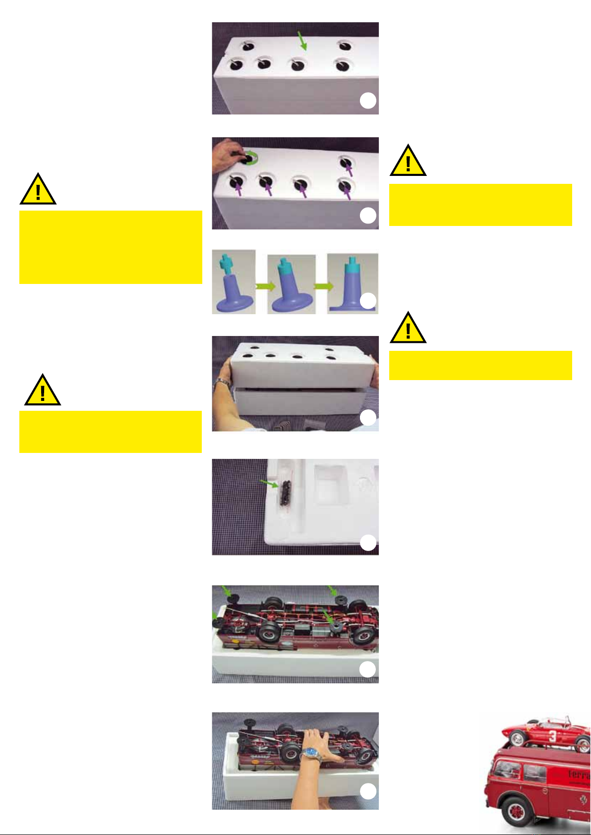
• Bitte stellen Sie die ungeöffnete (ver-
klebte) Styropor-Box auf den Kopf. Die
Modell-Schraubenbefestigung ist von
oben sichtbar. (Abbildung 1)
• Lösen Sie die Schraubknebel entgegen
dem Uhrzeigersinn und ziehen Sie sie
zusammen mit den Tellerstützen aus der
Box heraus. (Abbildung 2)
Hinweis: Wenn Sie das Modell zur Ent-
lastung der Radaufhängungen mit einer
Abstützung unterbauen wollen, werden
dazu vier der zuvor entfernten Tellerstüt-
zen benötigt.
(Abbildung 3)
• Schneiden Sie die Verklebung der Box
rundum an der Trennfuge auf und heben
Sie das Styropor-Unterteil ab.
(Abbildung 4)
2. Anbringung der Tellerstützen
Hinweis: Wird eine Abstützung auf Tel-
lerstützen nicht gewünscht, bitte unter 3.
fortfahren. )
Wegen seines hohen Eigengewichtes von
ca. 4 kg empfehlen wir, das Modell mit
den zur Verfügung stehenden Tellerstüt-
zen zu unterbauen, um langfristig die
Radaufhängungen zu entlasten bzw. Ab-
plattungen der Reifen zu vermeiden.
• Komplettieren Sie vier Tellerstützen mit
den im Styropor-Deckel mitgelieferten
Adaptern (Abbildung 5 und 3). Danach
drücken Sie die Tellerstützen mit dem Ad-
apter in die vier mit Pfeil gekennzeichne-
ten Gewindedome der Bodenplatte ein.
Achten Sie dabei auf einen festen Sitz.
(Abbildung 6 + 7)
3. Umdrehen des Modells auf Teller-
stützen bzw. Räder
• Greifen Sie mit einer Hand in der Mit-
te unter den Styropor-Deckel. Die andere
Hand fasst vorsichtig den mittleren Teil
der Modell-Bodengruppe an. Achtung
Beschädigung vermeiden! Danach wird
das Modell zusammen mit dem Styropor-
Oberteil umgedreht und auf die Teller-
stützen bzw. Räder abgestellt. Danach
nehmen Sie das Styropor-Oberteil vor-
sichtig ab. Bitte bewahren Sie die Styro-
1. Removing the model from the box
• Please stand the closed styrofoam box
(still taped) on its face to reveal the screws
in the bottom. (Illustration 1)
• Turn the toggle screws counter-clockwi-
se and remove them one by one, together
with the trestles. (Illustration 2)
Note: When you install stands on which
to sit the model later, you will need four
of the trestles just removed. (Illustration 3)
• Cut the Scotch tape along the slit on
both sides to remove the bottom half of
the styrofoam box. (Illustration 4)
2. Installation of the trestles
Note: In case you want to skip this step,
just move on to 3.
Because the model weights heavy -- ap-
proximately 4 kg, we recommend instal-
lation of the trestles to release the wheel
suspensions from constant pressure and
to forestall possible deformation of tires
in the long run.
• Insert the four trestle heads that are enc-
losed in the top half of the styrofoam box
(Illustration 3 and 5). Now push the fully-
assembled trestles into the four sockets
of the base plate that are marked with
arrows. Make sure that they are installed
tight and properly (illustration 6 + 7)
3. Flipping the model over to stand
on the trestles or the wheels
• Grab the middle of the styrofoam with
one hand and hold the middle of the un-
dercarriage with the other hand. Be ca-
reful not to cause any damage! Turn the
styrofoam over (with the model still held
in it) so that it comes on top, and gently
let the model stand on the trestles or its
wheels. Remove carefully the styrofoam.
Reserve the packing materials and box.
They will come in
handy if you should
pack the model
again in the future.
(Illustration 8 + 9)
ACHTUNG!
1
2
3
4
ACHTUNG!
ATTENTION!
ATTENTION!
5
6
7
por-Verpackung und die Befestigungstei-
le auf, damit Sie diese bei einem späteren
Transport wieder verwenden können.
(Abbildung 8 + 9)
Hebebühne
Im Anlieferungszustand ist die Hebebüh-
ne auf die oberste Position eingestellt
und fest fixiert. Mit dieser Hebebühnen-
Grundeinstellung entfaltet das Modell
seine ganze Strahlkraft und ist darauf
vorbereitet, drei Ferrari Modelle aufzu-
nehmen.
Die Hebebühne selbst lässt sich manuell
mit Fingerkraft vertikal absenken und
wieder nach oben bewegen.
Häufige Auf- und Abwärtsbewegungen
sollten vermieden werden, da sonst Schä-
den nicht auszuschließen sind.
Betätigung der Hebebühne
Absenken
• Seitlich eingeschobene Auffahrrampen
herausnehmen. Dazu auf jeder Fahrzeug-
seite die beiden Schraubknebel lösen.
(Abbildung 10)
• Obere Arretier-Schraubknebel der He-
bebühne (zusammen je zwei auf der
linken und rechte Seite) entgegen dem
Uhrzeigersinn zu ca. 2/3 Länge heraus-
drehen. (Abbildung 11)
• Mit Daumen sowie Zeige- und Mittel-
finger beider Hände die beiden Querste-
ge der Hebebühne umfassen und He-
bebühne vorsichtig mit gleichmäßigem
Druck nach unten bewegen. Es kann jede
beliebige Zwischenhöhe eingestellt wer-
den. (Abbildung 12)
Eine Absenkung ganz nach unten, bis die
Hebebühne auf den unteren Standschie-
nen aufliegt, ist ebenfalls möglich.
Anheben
Die Anhebung der Bühne erfolgt in um-
gekehrter Reihenfolge.
• For moving the model around, it is re-
commended that you use both hands to
hold the front and the back of the under-
body from underneath.
Auto Hoist
In the condition of delivery, the auto hoist
is adjusted to the highest position. In this
factory setting, the transporter is ready
to be loaded with three 1:18 scale Ferrari
models.
The auto hoist can be operated manually
in upward and downward directions.
Please don’t use this operation frequent-
ly, for it employs a delicate mechanism
which is not meant to be toyed around.
Abuse will reduce the model to a less
than a perfect condition.
Operation of the auto hoist
Lowering
To remove the sidewise shelved ramps, un-
fasten the toggle screws. (Illustration 10)
• Unscrew counter-clockwise the upper ad-
justment toggle screws of the auto hoist (2
on the left side and 2 on the right side) until
they are out about two thirds of their total
lengths. (Illustration 11)
• Use your thumb, index and middle  nger
of both hands to push down the two cross
webs of the auto hoist slowly and evenly
in a parallel manner. The auto hoist will
stay on any position where you put it till
you reach the floor where the auto hoist
touches the ramps of the lower deck. (Il-
lustration 12)
Lifting
The lifting of the auto hoist is a reversal
of the operation above.
• You can bring it back to the upper
deck position (factory setting), where the
ramps level with the roof, and the auto
hoist will stay put with tightened togg-
le screws. Note that the auto hoist must
be so aligned that the toggle screws can
go into the center of
its guide rolls. Then
turn the toggle
screws tight clock-
wise to hold the
auto hoist at this
level.
ACHTUNG!
ATTENTION!
8
9
10
11
12
• In der obersten Hebebühnenposition
(Grundeinstellung ab Werk) bilden die
Standschienen mit den fest verschraubten
Dachschienen eine Ebene. Die Gleitrollen
der Hebebühne dabei so positionieren,
dass die oberen Schraubknebel im Uhr-
zeigersinn in das Zentrum der Gleitrollen
eingedreht werden können. Danach ist
die Hebebühne wieder arretiert.
Montage der Auffahrrampen
• Die seitlich an der Hebebühne ein-
geschobenen Rampen vorsichtig nach
hinten herausziehen. Zuvor auf beiden
Seiten die beiden Schraubknebel lösen.
(Abbildung 13)
• Fahrzeug-Heckklappe an der Innenseite
entriegeln und abklappen. (Abbildung 14)
• Die beiden Rampen mit der vorgesehe-
nen Lasche an den fahrzeugfesten Stand-
schienen einhängen. (Abbildung 15)
• Rückmontage der beiden Auffahrram-
pen in umgekehrter Reihenfolge.
Bewegliche Teile – Fahrzeugfront
• Nach vorne abklappbare Frontkonsole
mit Fiat-Logo und dahinter liegendem
Kühlereinfüllstutzen mit zu öffnendem
Deckel. (Abbildung 16)
• Einstellbare Außenspiegel links/rechts.
Der Spiegelarm und der Spiegel selbst
lassen sich nach innen und nach außen
schwenken. (Abbildung 17)
Rechte Fahrzeugseite
• Fahrertüre zum Öffnen.
• Die zweiügelige Türe des Werkstat-
traumes lässt sich öffnen (Verriegelungs-
gestänge am linken Türflügel ohne Funk-
tion) (Abbildung 18)
• Drei kleine Karosserieklappen. Alle drei
Klappen lassen sich nach unten öffnen.
Zwei der Klappen dienen als Zugang zum
jeweiligen Tankeinfüllstutzen der Doppel-
kraftstofftanks. Die dritte Klappe ist als
Trittstufe für den Aufgang zur Hebebüh-
nenleiter vorgesehen. (Abbildung 19)
• Die Klappe mit Ferodo-Aufschrift lässt
nach oben öffnen. Dahinter befindet sich
eine herausziehbare Schublade mit sechs
Unterlegkeilen. Sie dienen dazu, die Fahr-
zeuge auf der Ladeäche vor dem Abrol-
len zu sichern. (Abbildung 20)
Mounting of the ramps
• Unfasten toggle screws and remove the
sidewise-shelved ramps carefully from
the rear end. (Illustration 13)
• Unlatch the tailgate door and let it
down. (Illustration 14)
• Place both ramps in connection with
the holding rail of the transporter. (Illus-
tration 15)
• To replace the ramps, reverse the process.
Movable parts – Front
• Hinged front console cover with Fiat
logo, over the radiator filler neck with a
flip-open cap. (Illustration15)
• Pivoting exterior mirrors with adjustable
arms on both sides. (Illustration 16)
Right side
• Driver-side door can open.
• The double-wing door of the inspection
bay can open (bar-slide of the left door is
without function) (Illustration 17)
• Three aps. All three covers can be
opened in a downward direction. Two of
them give access to the fuel filler necks
of the double tanks. The third one covers
a step leading to the auto hoist ladder.
(Illustration 18)
• The cover with the script of Ferodo
opens upwards to reveal a drawer hol-
ding 6 stop blocks, which serve to keep
stowed cars in place. (Illustration 19)
Left side
• Front passenger-side door can open.
• Two hinged covers give access to the
storage and battery boxes. The cover of
the battery box can open downwards, as
well. (Illustration 20)
13
14
15
16
17
18
Linke Fahrzeugseite
• Beifahrertüre zum Öffnen.
• Zwei bewegliche Klappen als Zugang
zu einem Stauraum und Batteriefach,
dessen gelochter Batteriefachdeckel sich
ebenfalls (nach unten) öffnen lässt.
(Abbildung 21)
• Die Klappe mit der Ferodo-Aufschrift
lässt sich nach oben öffnen. Hinter der
Klappe befindet sich das herausnehmba-
re Ersatzrad. Dazu muss der Spannbügel-
griff leicht angehoben und geöffnet wer-
den. Anschließend Reifenhalter seitlich
nach links wegschwenken. Danach lässt
sich das Ersatzrad aus der Halterung he-
rausnehmen. Rückmontage des Ersatzra-
des in umgekehrter Reihenfolge.
(Abbildung 22)
Fahrzeugheck
• Die Heckklappe lässt sich nach unten
öffnen. Dazu ist die Stangenverriegelung
an der Klappeninnenseite durch Umlegen
des Hebels zu entriegeln. (Abbildung 23)
• Die Abdeckblende für die dahinterlie-
gende Anhängerkupplung kann abge-
nommen werden. Blende im abgeklapp-
ten Zustand nach oben mit leichtem
Druck aus der Lagerung ausklinken.
Bitte mit äußerster Vorsicht vorge-
hen; Klappe nicht verkanten!
(Abbildung 24)
• Die Anhängerkupplung hinter der Ab-
deckblende lässt sich in vertikaler Rich-
tung auf- und abschwenken. Der Anhän-
gerbolzen kann mit einer Pinzette nach
oben herausgezogen werden. Der Bolzen
ist mit einem Kettchen gegen Verlust ge-
sichert.
• Rückmontage der Klappe: Lagerzap-
fen der Klappe in vorgegebene Schlitze
ansetzen und mit leichtem Druck nach
unten einrasten lassen. Vorsicht, ligrane
Teile!
• Hintere, obere Hebebühnen-Verstre-
bung. Die beiden Verstrebungsarme
lassen sich nach dem Entfernen des ein-
gesteckten Knebels nach außen schwen-
ken. (Abbildung 25)
Fahrerhaus-Innenraum
• Die Motorabdeckhaube kann in Rich-
tung Innenraumrückwand bis zum An-
schlag angehoben werden. Beiliegendes
Werkzeug verwenden. (Abbildung 26)
• The cover with the script of Ferodo can
open upwards to reveal a removable spa-
re wheel. Just lift the spring clip a little to
open it. Pull the wheel holder out sidewi-
se to your left. The spare wheel can be
removed now. To replace the wheel, just
reverse these steps. (Illustration 21)
Rear end
• The tailgate door can open. To do so,
unlatch the bar-slide from the inside. (Il-
lustration 22)
• The cover for the hitch can be remo-
ved. Flip open the cover and exert a little
pressure to remove it from the holders.
Please act very carefully so as not to
twist the cover plate. (Illustration 23)
• The tow hitch behind the cover plate is
movable in an up-and-down direction, and
the hitch bolt can be released upwards with
a tweezers. The bolt is also chain-protected
so that you will not lose it.
• To replace the cover plate, ease the axle
studs of the cover into the entry slots and
click them into place with a little pressu-
re. But be careful, for these parts are very
delicate.
• The rear upper struts can be discon-
nected and swing out horizontally if the
latch lock is removed. (Illustration 24)
19
20
21
22
23
24
ATTENTION!
Driver cabin
• The engine cover can ip open from the
front. Please use the attached tool. (Illust-
ration 25)
• Pivoting sun shades. (Illustration 26)
• Functional steering wheel, which can
turn the front wheels to the left and right.
Use the steering wheel only when the mo-
del sits on trestles. Otherwise the steering
system can be damaged by heavy weight.
• Adjustable co-pilots seat. To move the
seat in forward and backward position just
push or pull carefully the backrest of the
seat.
Note: The model is equipped with a func-
tional rotary drive shaft.
• Die beiden Sonnenblenden sind be-
weglich. (Abbildung 27)
• Lenkung: Die Vorderräder lassen sich
über das Lenkrad rechts und links ein-
schlagen. Die Lenkung sollte nur bei auf-
gebocktem Modell betätigt werden. Ein
Lenkeinschlag direkt an den beiden Vor-
derrädern kann zu Beschädigungen füh-
ren und ist daher zu unterlassen.
• Einstellbarer Beifahrersitz. Um den Sitz
nach vorne und nach hinten zu verschie-
ben, an der Rückenlehne vorsichtig drü-
cken oder ziehen bis zum Anschlag.
Hinweis: Das Modell ist mit drehbaren
Kardanwellen ausgestattet. Der Antrieb
erfolgt über die Hinterräder, wenn das
Modell vorwärts und rückwärts bewegt
wird.
ACHTUNG!
25
26
27
Handmontiert aus 3.115 Teilen stellt der rund 50 Zentimeter lange Ferrari-
Renntransporter die hohe Modellbaukunst und Leistungsfähigkeit von
CMC unter Beweis. Ein Traummodell, das einmal mehr neue Maßstäbe
setzt!
Wir wünschen Ihnen viel Freude mit diesem wertvollen
Sammlerstück. Sie werden es sicher pfleglich und mit viel Liebe
behandeln.
This Ferrari race car transporter replica is assembled from 3,115 single
parts and measures approximately 50 cm long. It is a true piece of art in
model building, which testifies to the extraordinary abilities of CMC. A
dream model like this is going to provide a new benchmark!
Have a lot of fun with this great model. It is a really valuable collec-
tor’s item. Treat it nice and with love.

Popular Motorized Toy Car manuals by other brands

King Motor Tyrant4 DS instruction manual

King Motor

King Motor Tyrant4 DS instruction manual

Jamara Lextron EP Instruction

Jamara

Jamara Lextron EP Instruction

Tamiya driftspec TT-02D user guide

Tamiya

Tamiya driftspec TT-02D user guide

Monogram KIT 0880 Assembly manual

Monogram

Monogram KIT 0880 Assembly manual

Traxxas Skully 36064-1 owner's manual

Traxxas

Traxxas Skully 36064-1 owner's manual

Helion Criterion HLNA0302 owner's manual

Helion

Helion Criterion HLNA0302 owner's manual

Hong Nor DM-ONE SPEC-e instruction manual

Hong Nor

Hong Nor DM-ONE SPEC-e instruction manual

Tamiya Raybrig NSX 2005 quick start guide

Tamiya

Tamiya Raybrig NSX 2005 quick start guide

Eduard VAB 6x6 interior quick start guide

Eduard

Eduard VAB 6x6 interior quick start guide

Mattel HotWheels RC Cybertruck instructions

Mattel

Mattel HotWheels RC Cybertruck instructions

Team Losi XXX-SCB user manual

Team Losi

Team Losi XXX-SCB user manual

Brassmasters Ivatt Pony Truck Assembly instructions

Brassmasters

Brassmasters Ivatt Pony Truck Assembly instructions

Kyosho Twin Force instruction manual

Kyosho

Kyosho Twin Force instruction manual

Carson X10 Dirt Warrior Sport 2.0 instruction manual

Carson

Carson X10 Dirt Warrior Sport 2.0 instruction manual

Kyosho MINI-Z Racer MR-02 RM Type instruction sheet

Kyosho

Kyosho MINI-Z Racer MR-02 RM Type instruction sheet

Huffy 6V owner's manual

Huffy

Huffy 6V owner's manual

Tamiya RAYBRIG NSX 2000 manual

Tamiya

Tamiya RAYBRIG NSX 2000 manual

Traxxas 7014 quick start guide

Traxxas

Traxxas 7014 quick start guide

manuals.online logo
manuals.online logoBrands
  • About & Mission
  • Contact us
  • Privacy Policy
  • Terms and Conditions

Copyright 2025 Manuals.Online. All Rights Reserved.