CMC EZTest User manual

HazMon System Tester
CMC Intrinsically Safe Sensor Bus
mDT001
EZTest
HazMon System Tester
Document No. 11584, Revision A02
January 2013

mDT001 HazMon System Tester Technical Manual /1
CMC INDUSTRIAL ELECTRONICS LTD
Phone: (604) 421-4425 Toll Free: (888) 421-4425
Fax: (604) 421-7734
The Industry Leader
in HazMon Technology
Table of Contents
1. Overview.........................................................................................................3
2. Description of Indicators .................................................................................4
3. Operation ........................................................................................................5
3.1 Using the Menu Control Pushbuttons………………….…………………..6
3.2 Sensor Test…………………………………………….…………………….6
3.3 Bus Test……………………………………………………….…………….10
3.4 Sensor Emulator……………………………………………………………11
3.5 Sensor Config………… …………………………………………………13
3.6 Battery Gauge………… …………………………………………………14
3.7 Battery Gauge………… …………………………………………………14
4. Troubleshooting Tips ....................................................................................15
5. Troubleshooting charts .................................................................................16
6. FAQ's............................................................................................................18
7. Specifications................................................................................................19
Table of Figures
Figure 1 - Illustration of Indicators…………………………………………..4

mDT001 HazMon System Tester Technical Manual /2
CMC INDUSTRIAL ELECTRONICS LTD
Phone: (604) 421-4425 Toll Free: (888) 421-4425
Fax: (604) 421-7734
The Industry Leader
in HazMon Technology
Revision Notes
First Release –October 18, 2012
Revision A01 –January 16, 2013
Update to include version 1.02 firmware features
Revision A02 –March 28, 2014
Fix main menu and configuration message

mDT001 HazMon System Tester Technical Manual /3
CMC INDUSTRIAL ELECTRONICS LTD
Phone: (604) 421-4425 Toll Free: (888) 421-4425
Fax: (604) 421-7734
The Industry Leader
in HazMon Technology
1. Overview
The EZTest HazMon System Tester provides a simple method to diagnose CMC HazMon systems.
The EZTest is handheld and operates off 2 AA batteries. It has an easy to read backlit LCD. A simple
4 button operator interface is provided
The EZTest provides a standalone good/bad test for individual sensors. In addition, the sensor’s
electrical interface and real-time output can be verified. All information is presented in scaled units to
simplify the test results.
In addition to testing individual sensors, the EZTest can be connected to an active CMC Intrinsically
Safe network. The EZTest will supply a simply good/bad indication of the networks operation. Further
details of the networks electrical operating condition are also provided.
The EZTest can also emulate a sensor. A sensor is first attached to the EZTest and after the serial
number is captured the EZTest is attached to the network. The keyboard can then be used to set any
value for the sensor.
The mVM001 Vibration Sensor and the mTS017 Infrared Temperature Sensor are configurable. The
EZTest provides a simplified means of configuring these sensors.
.

mDT001 HazMon System Tester Technical Manual /4
CMC INDUSTRIAL ELECTRONICS LTD
Phone: (604) 421-4425 Toll Free: (888) 421-4425
Fax: (604) 421-7734
The Industry Leader
in HazMon Technology
2. Description of Indicators
Figure 1 - Illustration of Indicators
There are five control pushbuttons:
Power
Press to turn power on or off
Select
Select the displayed function
Back
Go back one menu level or exit this function
Down
Next menu item
Up
Previous menu item

mDT001 HazMon System Tester Technical Manual /5
CMC INDUSTRIAL ELECTRONICS LTD
Phone: (604) 421-4425 Toll Free: (888) 421-4425
Fax: (604) 421-7734
The Industry Leader
in HazMon Technology
3. Operation
The EZTest HazMon System Tester has an easy to use menu system. To turn on the tester, press
and hold the “POWER” key until the display backlight illuminates. To turn the tester off, press and hold
the “POWER”key until the display backlight goes off. The tester automatically turns off after 5 minutes
except under the following conditions:
1. The tester is displaying real-time information from a sensor;
2. The tester is in “Bus Test” mode (the tester must be powered in “Bus Test” mode or it will
cause the network to fault when connected).
The system will display two opening messages when power is turned on:
The tester may display a status message before proceeding to the main menu. The status messages
are as follows:
The main menu is then displayed:
Message
Description
Required Action
Battery Low
< 25%
The battery has
discharged below 25%
Check the battery level using the
“Battery Gauge” function. If less than
10% replace the batteries
Program CRC
Fault
The tester’s program is
corrupted
Return the unit to the factory for repair
Data RAM
Fault
The tester failed self-test
Return the unit to the factory for repair
Calibration
Fault
The calibration
parameters are corrupted
Return the unit to the factory for repair
CMC Industrial
Electronics
EZTest Ver 1.00
Copyright 2012
Select Function
Sensor Test

mDT001 HazMon System Tester Technical Manual /6
CMC INDUSTRIAL ELECTRONICS LTD
Phone: (604) 421-4425 Toll Free: (888) 421-4425
Fax: (604) 421-7734
The Industry Leader
in HazMon Technology
3.1 Using the Menu Control Pushbuttons
There are four menu control pushbuttons:
Select
Select the displayed function
Back
Go back one menu level or exit this function
Down
Next menu item
Up
Previous menu item
There are three menu selections from the main menu. These are selected using the “UP” and
“DOWN” pushbuttons.
Sensor Test
Test an individual sensor
Bus Test
Test the CMC Intrinsically Safe network
Sensor Emulator
Emulate a sensor
Sensor Config
Configure a sensor
Battery Gauge
Check remaining battery level
Once the function is displayed, it is executed by pressing the “SELECT” pushbutton.
3.2 Sensor Test
The sensor test will report the health of a single sensor plugged into the modular connector on the
front of the unit. In addition, the sensor test will check for any ground fault conditions between the
sensor wiring and the metal case of the sensor.
************************************************ Caution *************************************************
Sensors connected to a bus converter on an active network or multiple sensors connected together
cannot be tested using this function. Connect a single standalone sensor the tester’s front panel
connector.
************************************************************************************************************
If “Sensor Test” is selected and no sensor is connected to the modular connector, the display will
indicate:
Sensor Test
No Sensor

mDT001 HazMon System Tester Technical Manual /7
CMC INDUSTRIAL ELECTRONICS LTD
Phone: (604) 421-4425 Toll Free: (888) 421-4425
Fax: (604) 421-7734
The Industry Leader
in HazMon Technology
To test a sensor, plug the sensor into the tester. If the sensor is a temperature sensor, plug the
ground fault test cable into the tester’s mini-phone jack and connect the alligator clip to the sensor’s
metal body. If the sensor’s metal body is not easily reached, connect the alligator clip to any metal
part that is connected to the sensor body. Only temperature sensors require the ground test lead.
When a sensor is connected to the modular jack and “Sensor Test” is selected, the display will first
indicate:
The following messages can be displayed:
Message
Description
Sensor Good
The sensor passed all of the tests and is operational. This test
confirms the electrical interface of the sensor is working properly.
Use the “DOWN”key to verify the sensor is providing the correct
output.
Supply Volts Low
The sensor is drawing too high a current from the networks power
supply.
Data Volts High
The sensor is loading the data line and the data high voltage is
lower than required.
Data Volts Low
The sensor is loading the data line and the data line low voltage is
higher than allowed.
Ground Fault
One of the sensor’s wires is in contact with the metal case of the
sensor or conducting to earth ground through moisture damage.
Red Wire Open
For temperature sensors this message indicates that the red
power wire to the sensor is open
Bad Data
The tester was unable to read a valid data packet from the sensor.
No Sensor
No sensor was detected, the sensor is defective
Sensor Test
Please Wait

mDT001 HazMon System Tester Technical Manual /8
CMC INDUSTRIAL ELECTRONICS LTD
Phone: (604) 421-4425 Toll Free: (888) 421-4425
Fax: (604) 421-7734
The Industry Leader
in HazMon Technology
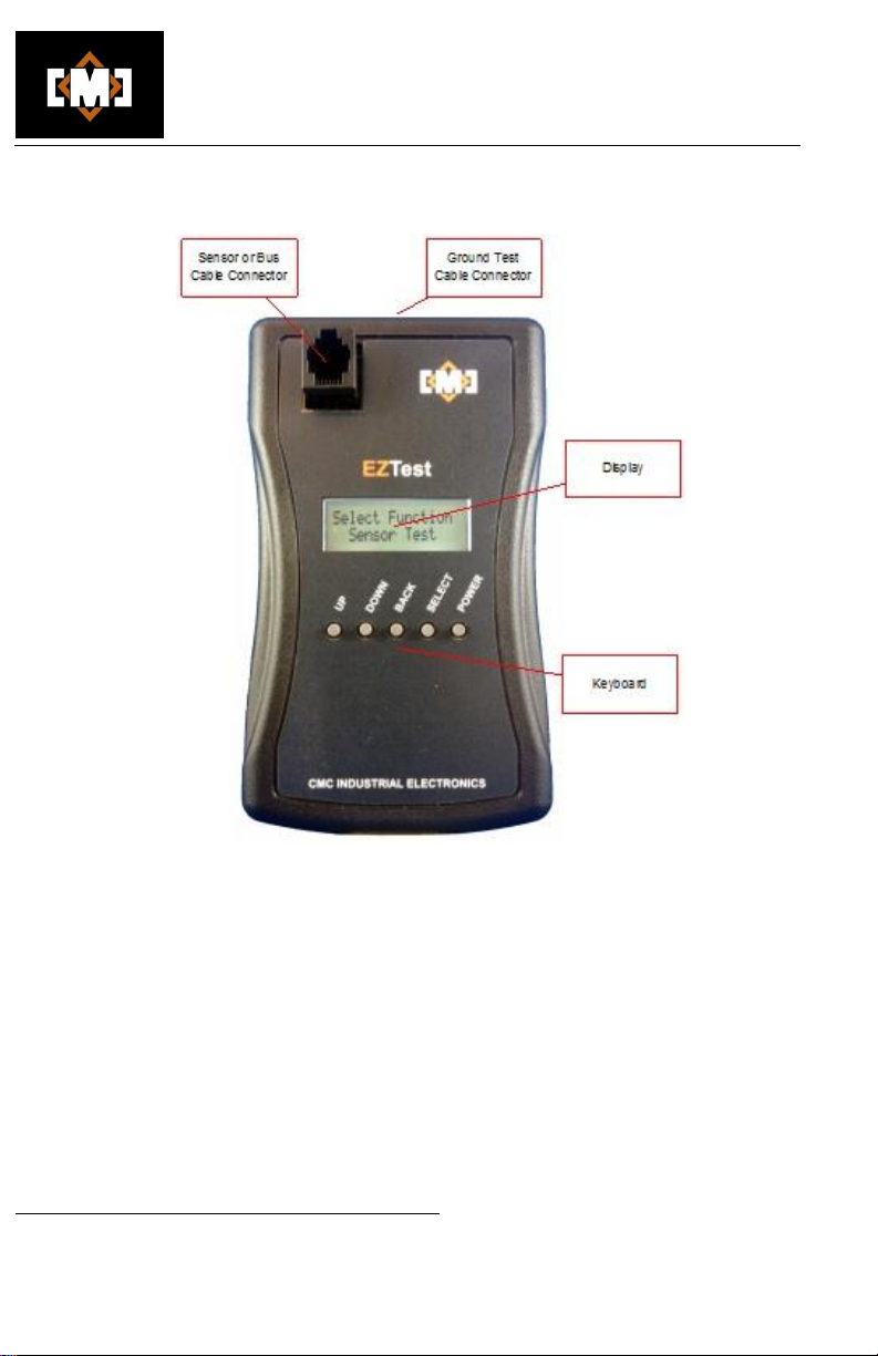
The “UP” and “DOWN” keys can be used to display further information about the sensor’s
performance. If the display indicates “Sensor Good”, use the “DOWN”key to verify the value being
returned by the sensor. The tester displays the sensor’s value in real world units for verification.
The following table describes the available display starting from the status display described above:
************************************************ Caution *************************************************
Only sensors that display the “Sensor Good” message and that are displaying the correct reading
using the real-time display should be used.
************************************************************************************************************
If a sensor is connected that does not provide a valid CMC family code, the sensor may be read, but
in the real-time display will show the sensor type “Unknown” and the units as “raw”. This sensor is
not a valid sensor for use on a CMC network.
Key
Function
Description
Down 1
Real-time display
The sensor type and real-time value for the sensor are
displayed in the units suitable for the sensor. Verify the
sensor’s output using this function.
Down 2
Serial number
display
The sensor’s serial number is displayed. The serial
number should agree with the serial number printed on the
sensor’s label.
Up 1
Sensor Power
The sensor power voltage level is displayed. If this voltage
is too low it indicates the sensor is drawing excessive
power.
Up 2
Sensor Data Low
The data low voltage level on the network is displayed. If
this voltage is too high, the sensor has resistance between
the green data wire and the red power wire.
Up 3
Sensor Data High
The data high voltage level on the network is displayed. If
this voltage is too low the sensor has resistance between
the green data wire and the white common wire.
Up 4
Ground Flt Data
The ground fault leakage voltage on the network is
displayed. If this voltage is too high the sensor has
resistance between the metal case and the green wire.
Up 5
Ground Flt Power
The ground fault leakage voltage on the power wire is
displayed. If this voltage is too high the sensor has
resistance between the metal case and the red wire.
Up 6
Ground Flt Common
The ground fault leakage voltage on the common wires is
displayed. If this voltage is too high the sensor has
resistance between the metal case and the white or black
wires.

mDT001 HazMon System Tester Technical Manual /9
CMC INDUSTRIAL ELECTRONICS LTD
Phone: (604) 421-4425 Toll Free: (888) 421-4425
Fax: (604) 421-7734
The Industry Leader
in HazMon Technology
The following table lists the allowable tolerance set for each of the sensors permitted on the CMC
network:
Model
Family
Code
Ground
Fault
Data
Maximum
Ground
Fault
Power
Maximum
Ground
Fault
Common
Maximum
Power
Supply
Minimum
Data
Low
Maxi
mum
Data
High
Maximum
mTS01X
40
0.25
0.25
0.25
4.75
0.25
3.85
mRS001
160
0.25
0.25
0.25
4.58
0.25
3.75
mVM001
161
0.25
0.25
0.25
4.58
0.25
3.75
mCM001
162
0.25
0.25
0.25
4.61
0.25
3.75
mRH001
163
0.25
0.25
0.25
4.66
0.25
3.75
mDI001
165
0.25
0.25
0.25
4.63
0.25
3.75
mTS017
166
0.25
0.25
0.25
4.67
0.25
3.75
mTC001
177
0.25
0.25
0.25
4.47
0.25
3.85
mAM001
178
0.25
0.25
0.25
4.61
0.25
3.75
mTC002
179
0.25
0.25
0.25
4.18
0.25
3.85

mDT001 HazMon System Tester Technical Manual /10
CMC INDUSTRIAL ELECTRONICS LTD
Phone: (604) 421-4425 Toll Free: (888) 421-4425
Fax: (604) 421-7734
The Industry Leader
in HazMon Technology
3.3 Bus Test
*********************************************** Warning *************************************************
Do not connect the tester to the network until the tester is turned on and “Bus Test” is selected. If the
tester is not powered, it will cause the network to fault.
************************************************************************************************************
The “Bus Test” reports the health of a CMC network. Common network faults such as a partially
shorted data bus or open data bus are detected. The tester also displays the number of sensors being
polled by the bus converter and the serial numbers of the sensors being polled.
************************************************ Caution *************************************************
The tester displays the sensors that are being polled by the bus converter. This display does not
indicate that those sensors are present on the network or responding to the poll request, only that
they are present in the bus converters polling list. Individual sensors should be verified using the
“Sensor Test”.
************************************************************************************************************
If “Bus Test” is selected and the tester is not connected to the network using the supplied patch
cable, the display will indicate:
When the tester is connected to a powered network, one of the following messages will be displayed:
Message
Description
Bus Good
No errors were detected on the bus
Please Wait
Wait while information is being collected
Power Volts Low
The network DC power is below 4.00VDC
Data Volts Low
The network data line DC level is below 3.90VDC
Data Stuck Low
Thenetwork data line level is stuck in the low state
Data Stuck High
The network data line level is stuck in the high state
The “UP” and “DOWN” keys can be used to display further information about the network’s
performance. The following table describes the available display starting from the status display
described above:
Bus Test
Power Volts Low

mDT001 HazMon System Tester Technical Manual /11
CMC INDUSTRIAL ELECTRONICS LTD
Phone: (604) 421-4425 Toll Free: (888) 421-4425
Fax: (604) 421-7734
The Industry Leader
in HazMon Technology
Key
Function
Description
Down 1
No. of Sensors
The number of sensors being polled by the bus
converter is displayed
Down 2 -33
Serial Number Display
Displays the serial numbers of the sensors being
polled by the bus converter
Up 1
Data Signal
The data line average voltage. The data line
should be above 3.5VDC.
Up 2
Power Signal
The power line average voltage. The power
supply should be above 4.5VDC.
The values displayed above can be used to further troubleshoot the system. If the display indicates an
error, use the standard troubleshooting procedure starting at the first field interconnect box to isolate
portions of the network. If the error is corrected when a branch is isolated, the problem will be in that
branch. Continue to the next field interconnect box and repeat until the field interconnect box causing
the error is found. The sensors in that box can then be individually tested to locate the defective
sensor.
3.4 Sensor Emulator
The tester can emulate most CMC sensors. Sensors that can have multiplexed output modes such as
the mTS017 and mVM001 will only be emulated as single mode devices. The mTC001 and mTC002
Thermocouple converters cannot be emulated. To emulate a sensor follow these steps:
1. Select “Emulate Sensor” from the main menu;
2. The display will indicate:
3. Once connected, the display will indicate the serial number of the sensor being emulated;
4. After displaying the serial number the display will indicate;
Connect sensor
to emulate
166-0-188- 58
230-0- 17- 52
Connect tester
To bus

mDT001 HazMon System Tester Technical Manual /12
CMC INDUSTRIAL ELECTRONICS LTD
Phone: (604) 421-4425 Toll Free: (888) 421-4425
Fax: (604) 421-7734
The Industry Leader
in HazMon Technology
5. Connect the tester to the bus using the supplied cable;
6. The display will now indicate the type of sensor being emulated and the value being sent to
the host system;
7. The “UP” and “DOWN” keys can be used to change the value. The range of values that can
be emulated are dependent on the sensor. Negative values are permitted for some sensors.
If the sensor cannot be emulated the display will show;
8. The “BACK’ key will terminate the emulation session. Disconnect the tester from the bus
before ending an emulation session.
mTS011
0.0 C 32.0 F
Sensor cannot
be emulated

mDT001 HazMon System Tester Technical Manual /13
CMC INDUSTRIAL ELECTRONICS LTD
Phone: (604) 421-4425 Toll Free: (888) 421-4425
Fax: (604) 421-7734
The Industry Leader
in HazMon Technology
3.5 Sensor Config
The tester can configure the mTS017 Infrared Temperature Sensor and the mVM001 Vibration
Sensor:
1. Select “Sensor Config” from the main menu;
2. The display will indicate:
3. Once connected, the display will indicate;
4. Once the serial number has been retrieved the display will momentarily indicate;
5. After displaying the serial number the display will indicate;
6. Once the current configuration of the sensor has been read the display will show the values
for the sensors configuration parameters. Use the “UP” and “DOWN” keys to select the
sensor parameter;
7. To change a sensor parameter, first select the parameter using the “UP” and “DOWN” keys
and then press the “SELECT” key. A left and right arrow will appear on the display
indicating it is in change mode. Use the “UP” and “DOWN” keys to set the value and then
press the “SELECT” key to confirm the value. The arrows will disappear when the value is
confirmed;
8. To save the values to the sensor, use the “DOWN” key until the display indicates;
Connect sensor
to configure
166-0-188- 58
230-0- 17- 52
Wait getting
Serial number
Getting config
> > > > > > > > > > >
Save
Press Select

mDT001 HazMon System Tester Technical Manual /14
CMC INDUSTRIAL ELECTRONICS LTD
Phone: (604) 421-4425 Toll Free: (888) 421-4425
Fax: (604) 421-7734
The Industry Leader
in HazMon Technology
9. Press the “SELECT” key to save the new values to the sensor. The display will indicate;
10. Once the configuration has been saved the display will indicate;
11. Press the “BACK” key to exit sensor configuration.
The parameters that can be configured are fully described in the Technical Manuals for the individual
sensors.
3.6 Battery Gauge
The battery gauge function displays the remaining capacity of the batteries in percent.
The tester uses 2 AA batteries that are located in a battery compartment in the rear of the tester. The
tester will remain active even if the battery indicator drops to 0%. The sensor reading may not be
accurate if the batteries are further discharged. Replace the batteries at 10% to ensure you have
adequate battery power when the tester is needed.
3.7 Battery Gauge
The battery gauge function displays the remaining capacity of the batteries in percent.
The tester uses 2 AA batteries that are located in a battery compartment in the rear of the tester. The
tester will remain active even if the battery indicator drops to 0%. The sensor reading may not be
accurate if the batteries are further discharged. Replace the batteries at 10% to ensure you have
adequate battery power when the tester is needed.
Battery Meter
95 %
Battery Meter
95 %
Saving config
> > > > > > > > > > >
Configuration
Saved

mDT001 HazMon System Tester Technical Manual /15
CMC INDUSTRIAL ELECTRONICS LTD
Phone: (604) 421-4425 Toll Free: (888) 421-4425
Fax: (604) 421-7734
The Industry Leader
in HazMon Technology
4. Troubleshooting Tips
The tester can only locate sensors that are faulted when they are connected to the tester. Sensors
that are intermittent can be more difficult to locate. Here are some tips to assist you in locating
problems:
1. Use the tester as soon as a fault occurs, as it is more likely the fault will be present when
you connect the tester.
2. Some faults are caused when the sensor’s cable becomes in contact with earth ground.
This is especially possible with the temperature sensors that have metal housings. These
faults can be very intermittent and are typically caused when the end of the cable is crimped
against the end of the sensor tube during installation. If the cable is subject to movement
from wind or other vibration sources it can wear through and short the cable to the metal
tube. These faults can be located using the ground test on the sensor tester. You may have
to move the conduit connection at the sensor to cause the fault.
3. In most cases, you do not need to use the tester to locate a bad sensor or wiring on the
network. The basic branch isolation technique is the easiest and fastest way to locate the
fault. The sensor test “Bus Test” can be deployed when a partially faulted sensor is
disrupting the network intermittently. The “Bus Test” measures the signal levels on the
cable system and reports if a sensor is loading the system. The traditional isolation
techniques can then be used to locate the sensor that is loading the system. The sensor
can then be verified using the “Sensor Test” function to confirm it is defective.
4. The “Sensor Test” function can also be used to verify sensors during the installation. It is
especially useful for speed sensors where the sensors reading can be immediately
compared to a handheld tachometer at the source.
5. The “Bus Test” function can also be used to verify that the expected serial numbers are
being polled by a bus converter. Once a system is commissioned and the sensor located
using the acquire function, the “Bus Test” function will display the sensors being polled by
the bus converter. If a sensor is being polled but is not responding then the wiring to the
sensor and the sensor itself should be verified.
A copy of the standard network troubleshooting guide is included with this manual. A full sized
laminated version is available from our sales office on request.

mDT001 HazMon System Tester Technical Manual /16
CMC INDUSTRIAL ELECTRONICS LTD
Phone: (604) 421-4425 Toll Free: (888) 421-4425
Fax: (604) 421-7734
The Industry Leader
in HazMon Technology
5. Troubleshooting charts
NO
NO
See "Troubleshooting
the Bus Converter RS-
485 Network"
YES
NO
YES
Is the "Faulted"
sensor plugged into in
this FIB?
YES
YES
NO
Locate the FIB where the
sensor is connected
NO
One or more sensors in
"Fault"
or not reading correctly
Check the "Status"
screen on the
EZSentinel128
or
WS1 Webserver
Are all installed bus
converters online?
Locate the first
bus converter with
faulted sensors
Are errors indicated?
Locate first Field
Interconnect Enclosure
(FIB)
Are both
the red and green
LEDs on in this FIB?
See chart above for error
codes
YES
Unplug and clean the
sensor connector with
99%+ isopropyl alcohol
on both the plug and jack
Is the sensor now
working correctly?
Replace sensor
and assign the new
serial number in WS1 or
EZ128
Error Cod es
Bus Conv erte r
WS1 Webse rver EZSentine l128 Red LED
Green LED CAT5 Cable Sensor Cable
Onlin e Onlin e green 1 sec on/ 1 sec off On Bus converter OK
Offline Online red n/a Off See "Troubleshooting the RS-485 Netwrok"
Bus Low Data shorted low 3 n/a Blue shorted to any white Green shorted to white or black
Bus High Data Shorted High 4 n/a Blue shorted to green, orange or brown Green shorted to red
Bus overload Bus power overload 1 n/a Green, orange or brown shorted to any white Red shorted to white or black
No sensors No sensor on bus 2 n/a Blue open or disconnect switches off Green ope n or sensor unplugge d
Other faults
Sensor reads 85C or 185F Green, orange and brown open Red open

mDT001 HazMon System Tester Technical Manual /17
CMC INDUSTRIAL ELECTRONICS LTD
Phone: (604) 421-4425 Toll Free: (888) 421-4425
Fax: (604) 421-7734
The Industry Leader
in HazMon Technology
Branch
B Switch
OFF
Turn "OFF" the Branch B
disconnect switch
OFF
Branch
B Switch
YES
NO
NO
YES
NO
YES
Turn "OFF" the Branch A
disconnect switch
Branch
A Switch
OFF
Are both
the red and green
LEDs now on?
NO
YES
Replace sensor
and assign the new
serial number in WS1 or
EZ128
NO
YES
Does the red LED
in the bus converter
flash code 2?
Is this the last sensor in
this FIB?
YES
NO
Check CAT5 cable
between this FIB and the
last for physical or water
damage and replace
cable or FIB
Unplug the sensors one
at a time
Unplug the bus converter
from the FIB
Is the bus
converter plugged
into this FIB?
Replace the FIB
Replace the bus
converter and acquire or
re-enter serial numbers
Are all sensors working? Done!
NO
YES
Turn the A or B switch
back "ON" and follow the
A or B cable to the next
FIB
Are both
the red and green
LEDs now on?
Are both
the red and green
LEDs now on?

mDT001 HazMon System Tester Technical Manual /18
CMC INDUSTRIAL ELECTRONICS LTD
Phone: (604) 421-4425 Toll Free: (888) 421-4425
Fax: (604) 421-7734
The Industry Leader
in HazMon Technology
FAQ’s
What is the most common cause of “Faults”?
oWater ingress into the wiring or FIB’s is the most common cause of
“Faults”.
Why are all the sensors on a bus converter “Faulted”?
oAll of the sensors on a CMC Intrinsically Safe network are wired in
parallel. A short circuit on one sensor can short the bus and “Fault”
all of the sensors.
All of the sensors on a single bus converter are indicating intermittent
“Faults” every once in a while?
oThe bus may have a partial short circuit. Partial short circuits can
occur after severe electrical storms or due to water ingress in the
wiring. Follow the procedure in the flowchart but instead of observing
the LED’s, observe the voltage on the blue/white and green/white
pairs. Both pairs should have 4-5VDC present, with the negative
lead on the white wire and the positive lead on the colored wire.
oYou can make a test cable from an old sensor. Join the white and
black wires together and measure between the white/black wires
and the green (data) and red (power) wires. The test cable can be
plugged into a spare jack in the FIB for testing.
oAs indicated in the flow chart, start at the first FIB after the bus
converter and work outwards. If the voltages return to normal when
the outbound cable(s) is disconnected using the disconnect
switches, then the partial short is further down the network. If the
voltages do not return to normal, disconnect the sensors one a time
to locate the partial short.
A sensor reads +85oC or +185oF, what is wrong?
oThe red wire in the sensor cable is open. Unplug the sensor and
clean both the plug and jack with 99% Isopropyl Alcohol. Replace
the sensor if the problem is not resolved.

mDT001 HazMon System Tester Technical Manual /19
CMC INDUSTRIAL ELECTRONICS LTD
Phone: (604) 421-4425 Toll Free: (888) 421-4425
Fax: (604) 421-7734
The Industry Leader
in HazMon Technology
6. Specifications
Description
Characteristic
Sensor bus
Voltage
Current
Communications
5 VDC
5.0 mA max
CMC Intrinsically Safe Bus
Power Supply
Battery
2 x AA
Environment
Temperature
Relative Humidity
-20 to 50C (-5 to 120F)
5 to 95% non-condensing
Dimensions
Length
Width
Depth 10o
140mm (5.5in)
80mm (3.3in)
25mm (1.0in)
This manual suits for next models
1
Table of contents
Popular Test Equipment manuals by other brands

Levenhuk
Levenhuk Ermenrich Zing WT20 user manual

WS Technologies
WS Technologies STB100 Operator's manual

Anritsu
Anritsu Site Master S112 user guide

Rangevision
Rangevision SPECTRUM Setup

ERICHSEN
ERICHSEN LINEARTESTER 249 operating instructions

Keysight Technologies
Keysight Technologies U9361C Measurement guide