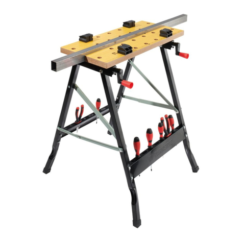
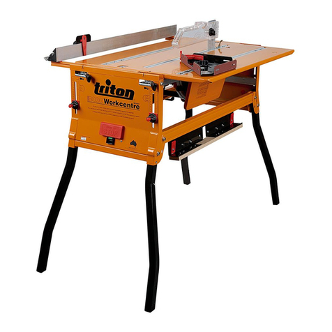
CMT ORANGE TOOLS CMT200-04 Assembly instructions

CMT200-04
Extension Tray
Bandeja de soporte
Plateau additionnel
Vassoio di supporto
Werkzeugablage
Thank you for purchasing this CMT200 workclamp. These instructions contain information necessary for safe and effective operation of this product.
Keep this manual close to hand and ensure all users of this tool have read and fully understand them.
Gracias por haber comprado esta abrazadera de trabajo CMT200. Estas instrucciones contienen información importante para el funcionamiento seguro y efectivo de
este producto. Conserve este manual a mano y asegúrese de que todos los usuarios de esta herramienta lo hayan leído y comprendido completamente.
Merci d’avoir acheté cet étau d’établi portable CMT200. Ces instructions contiennent des informations nécessaires pour le fonctionnement correct et en toute sécurité
de ce produit. Conserver ce mode d’emploi à portée de main pour référence et s’assurer que tous les utilisateurs de cet outil ont lu et compris toutes les instructions.
Grazie per aver acquistato il banco morsa da lavoro portatile CMT200 Queste istruzioni contengono le informazioni necessarie per un funzionamento sicuro ed efficace
del prodotto. Tenere il manuale a portata di mano e assicurarsi che tutti gli utenti l’abbiano letto e compreso completamente.
Wir danken Ihnen, dass sie das tragbare Spann- und Arbeitssystem CMT200 gewählt haben. Die vorliegende Anleitung enthält die notwendigen Informationen für
einen sicheren und korrekten Einsatz des Produktes. Halten Sie diese Anleitung immer griffbereit und sorgen Sie dafür, dass alle Benutzer des Systems sie vollständig
gelesen und verstanden haben.
www.cmtutensili.com
EN
OPERATING & SAFETY INSTRUCTIONS P. 2 - 3
ES
INSTRUCCIONES DE FUNCIONAMIENTO Y SEGURIDAD P. 4 - 5
FR
MODE D’EMPLOI ET CONSIGNES DE SÉCURITÉ P. 6 - 7
IT
ISTRUZIONI DI SICUREZZA E DI FUNZIONAMENTO P. 8 - 9
DE
GEBRAUCHS- UND SICHERHEITSANLEITUNG S. 10 - 11

COMPONENTS
1. Support arm
2. Tool tray
3. Folding arms
4. Mounting knobs
5. Stops
6. Pivot knobs
7. Spacers
Components2
3
76
4
5
2
13
4

ASSEMBLY
1. Unfold the folding arms (3) and rotate the mounting knobs (4) so that they are squared up with the
ends of the arms.
2. Feed them into the first set of mounting holes in the side of the
Portable Work Station and push them in until the stops (5) locate
against the Portable Work Station body.
The Extension Tray can be fitted to the left or right hand
side of the Portable Work Station.
3. Rotate the mounting knobs 45° to lock them in position.
4. Locate the tool tray (2) between the folding arms.
If fitting a second Extension Tray to your Portable Work Station, fit it the next series of
mounting holes on the opposite side to the first tray.
If using the Portable Work Station with the jaw reversed
(wide clamping position) the Support arm (1) can be
positioned higher so that it is level with the base of the
moving jaw. Loosen the Pivot knobs (6) until the spacers
(7) can be separated and the top spacer rotated 90°.
Re-tighten the knobs.
WARRANTY
Model: CMT200-04
Serial Number: _________________________
Retain your receipt as proof of purchase.
(Located on motor label)
CMT warrants to the purchaser of this product
that if any part proves to be defective due to
faulty materials or workmanship within 1 YEAR
from the date of original purchase, CMT will
repair, or at its discretion replace, the faulty part
free of charge.
This warranty does not apply to commercial
use nor does it extend to normal wear and tear
or damage as a result of accident, abuse or
misuse.
If the productis faulty or requires service please
refer to your nearest authorised CMT Repair
Centre. Warranty does not include any freight to
and from the user.
Assembly - Warranty 3

COMPONENTES
1. Brazo de soporte
2. Bandeja
3. Brazos plegables
4. Pomos de montaje
5. Topes
6. Pomos de pivote
7. Distanciadores
Componentes4
3
76
4
5
2
13
4

MONTAJE
1. Abrir los brazos plegables (3) y apretar los pomos de montaje (4), para que queden colocados en el
extremo de los brazos.
2. Insertar los pomos de montaje en los primeros agujeros en el lado
de su abrazadera de trabajo y empujarlos hasta que los topes (5)
toquen la estructura de la abrazadera.
La bandeja puede ser colocada en el lado derecho o
izquierdo de su abrazadera de trabajo.
3. Girar 45º los pomos de montaje (4) para fijarlos.
4. Insertar la bandeja (2) entre los brazos plegables (3).
Si el usuario desea utilizar una bandeja más, utilizar los agujeros siguientes en el lado
opuesto a la primera bandeja.
Si el usuario desea trabajar con la mordaza puesta al
revés (para permitir una sujeción ancha), debe colocar el
brazo de soporte (1) más alto, para que quede alineado
con la base de la mordaza móvil. Posteriormente, aflojar
los pomos de pivote (6) hasta que los distanciadores (7)
se separen y el anillo distanciador superior gire 90º .
Sujete los pomos de nuevo.
Código: CMT200-04
Número de serie: ________________________
Guarde el recibo como justificante de la compra.
GARANTÍA
(detallado en la etiqueta del producto)
En caso de piezas defectuosas, CMT reparará o
reemplazará dichas piezas de manera gratuita,
siempre que se encuentre dentro del plazo de
un año desde la fecha de compra.
La garantía no se aplica en caso de daños
por uso comercial o en caso de desgaste y/o
roturas causadas por accidentes y/o mal uso.
La garantía no cubre los daños ocasionados
por el transporte.
Si necesita asistencia, rogamos consulte con su
taller CMT más cercano.
Montaje 5

COMPOSANTS
1. Bras de support
2. Plateau
3. Bras repliable
4. Molettes de montage
5. Arrêts
6. Molettes de pivot
7. Bagues de distance
Composants6
3
76
4
5
2
13
4

MONTAGE
1. Déplier les bras repliables (3) et arranger les molettes de montage (4), de façon à ce que celles-ci
soient placées sur les extrémités des barres.
2. Insérer les bras repliables dans les trous sur le côté de votre CMT200
et pousser jusqu’à ce que les arrêts soient contre le même corps du
CMT200.
Le plateau additionnel peut être placé soit sur le côté
droit soit sur le côté gauche de l’établi.
3. Tourner les molettes de montage (5) de 45° pour les serrer.
4. Insérer le plateau additionnel (2) entre les bras repliables (3).
Si on souhaite insérer un deuxième plateau à votre CMT200, utiliser les trous successifs
sur le côté opposé au premier plateau.
Si l’usager désire utiliser le CMT200 avec l’étau renversé
(pour obtenir des serrages larges), le bras de support (1)
peut être placé plus en haut, pour qu’il soit aligné avec
l’étau mobile. Desserrer les molettes de pivot (6) jusqu’à
ce que les bagues de distance (7) se séparent et que
la bague de distance supérieure tourne de 90°. Serrer à
nouveau les molettes.
GARANTIE
Référence: CMT200-04
Numéro de série: _______________________
Garder votre reçu comme preuve d’achat.
(sur l’étiquette du produit)
CMT garantit à l’acheteur de ce produit que si
toute pièce s’avère défectueuse en raison de
la qualité des matériaux ou de la fabrication
pendant l’année suivant la date d’achat, CMT
réparera ou remplacera gratuitement, les pièces
défectueuses.
Cette garantie ne couvre pas un usage
commercial ni une usure normale ou un
dommage résultant d’un accident, d’un usage
abusif ou d’une mauvaise utilisation.
Si le produit est défectueux ou nécessite une
réparation, adressez-vous à l’atelier CMT agréé
le plus proche. La garantie n’inclut pas les frais
d’envoi de et vers l’utilisateur.
Montage - Garantie 7

COMPONENTI
1. Barra di sostegno
2. Vassoio
3. Barre ripieghevoli
4. Manopole di montaggio
5. Fermi
6. Manopole perno
7. Distanziali
Componenti8
3
76
4
5
2
13
4

MONTAGGIO
1. Spiegate le barre ripieghevoli (3) e sistemate le manopole di montaggio (4), in maniera tale che siano
ben collocate sulle estremità delle barre.
2. Inseritele nei primi fori sul lato del vostro banco da lavoro e spingete
fino a che i fermi (5) siano contro la struttura del banco.
Il vassoio di supporto può essere inserito sia sul lato
destro che su quello sinistro del banco da lavoro.
3. Ruotate le manopole di montaggio (4) di 45° per bloccarle.
4. Inserite il vassoio di supporto (2) tra le barre pieghevoli (3).
Se si vuole inserire un secondo vassoio al vostro banco, utilizzate i fori successivi sul lato
opposto al primo vassoio.
Se si vuole utilizzare il banco da lavoro con la morsa
invertita (per serraggi di grandi dimensioni), la barra di
sostegno (1) può essere collocata più in alto, così che
sia sullo stesso livello della base della morsa mobile.
Allentare le manopole perno (6), fino a ché i distanziali
(7) si separino e l’anello distanziale superiore ruoti di
90°. Serrare nuovamente le manopole.
GARANZIA
(collocato sull’etichetta del prodotto)
Articolo: CMT200-04
Numero di serie: ________________________
Conservate la ricevuta come certificato di acquisto.
CMT informa l’acquirente del prodotto che,
in caso di guasti dovuti a materiali difettosi o
difetti di produzione segnalati entro un anno
dalla data di acquisto, CMT riparerà o sostituirà
gratuitamente le parti difettose.
La garanzia non è applicabile per danni derivati
da uso commerciale o in caso di usura o rotture
provocate da incidenti o usi inappropriati.
Se il prodotto è difettoso e necessita assistenza
si faccia riferimento all’officina CMT autorizzata
più vicina. La garanzia non copre avarie o danni
causati durante il trasporto.
Montaggio - Garanzia 9

BESTANDTEILE
1. Tragarm
2. Werkzeugablage
3. Aufklappbare Arme
4. Montageknöpfe
5. Halter
6. Drehknöpfe
7. Distanzringe
Bestandteile10
3
76
4
5
2
13
4

GARANTIE
(auf dem Etikett gedrückt)
Bestell-Nr: CMT200-04
Seriennummer: ________________________
Bewahren Sie die Quittung als Kaufbeleg.
Im Falle von Produktteile mit Defekte oder
Schäden infolge der verwendeten Materialen
oder der Produktionsfehler, die innerhalb einem
Jahr mittgeteilt werden, wird CMT sie kostenlos
ersetzen oder reparieren.
Die Garantie gilt nicht für Schäden infolge
gewerblicher Verwendung oder bei Verschleiß
oder Bruch durch Unfall oder unsachgemäße
Gebrauch entstanden sind.
Wenn das Produkt defektiv ist oder technische
Unterstützung benötigt, wenden Sie sich an die
nächste berechtigte CMT Werkstatt. Die Garantie
gilt nicht für Schäden infolge des Transports hin-
und vom Käufer.
EINSTELLUNG
1. Entfalten Sie die aufklappbare Arme (3) und setzen Sie die Montageknopf (4) ein, damit sie am Ende
der Arme festhalten.
2. Setzen sie die aufklappbaren Arme in die Löcher Ihrer Werkbank
ein und drücken Sie bis die Halter (5) gegen das Gestell der Bank
ansetzen.
Die Werkzeugablage kann entweder auf die linke oder die
rechte Seite der Werkbank eingesetzt werden.
3. Drehen Sie die Montageknöpfe (4) um 45°, um sie zu sperren.
4. Setzen Sie Ihre Werkzeugablage (2) auf die Aufklappbaren Arme (3)
ein.
Wenn Sie eine weitere Ablage einsetzen möchten, verwenden Sie die folgenden Löcher auf
der gegenüberliegenden Seite der Werkbank.
Wenn Sie IhreWerkbank mit der umgekehrten Spannbacke
verwenden möchten, um eine weitere Spannoberfläche zu
erhalten, können Sie den Tragarm (1) höher setzen, damit
dieser auf die Bewegliche Spannbacke gerichtet ist.
Lockern Sie die Drehknöpfe (6) auf, bis die Distanzringe
(7) sich abscheiden, und der höchste Ring um 90° dreht.
Klemmen Sie wieder die Knöpfe ein.
Einstellung - Garantie 11

www.cmtutensili.com
© C.M.T UTENSILI S.P.A.
Questo documento
è stato inviato solo
per uso personale.
Qualsiasi uso
o riproduzione è
proibito senza il
permesso scritto
di C.M.T. UTENSILI
S.P.A.
Stampato in Italia
This document
has been sent for
your personal use
only. All usage and
reproduction is
forbidden without
written permission
from
C.M.T. UTENSILI
S.P.A.
Printed in Italy
Dieses Dokument
dient nur dem
persönlichen
Gebrauch. Jegliche
Nutzung oder
Vervielfältigung ist
ohneschriftliche
Erlaubnis
der Firma
C.M.T. UTENSILI
S.P.A. untersagt.
Gedruckt in Italien
Document envoyé
seulement pour
usage personnel.
Toute utilisation
ou reproduction
est interdite sans
l‘autorisation écrite
de C.M.T. UTENSILI
S.P.A.
Imprimé en Italie
Este documento
ha sido realizado
solo para uso
personal.
Se prohíbe todo tipo
de uso o
reproducción
sin la autorización
escrita de C.M.T.
UTENSILI S.P.A.
Impreso in Italia
TM: CMT, the CMT logo and the orange color applied to tool surfaces are trademarks of C.M.T. UTENSILI S.P.A.
Table of contents
Languages:
