CNTECH CR7 User manual
CR7
www.moduliaggiuntivi.com
POWER BOX CR7
Installation manual
CNTECH CR7 is a power box fully digital microprocessor controlled. llows
the increase in performance of turbodiesel vehicles with supercharged
common rail injection system. The increase in power and torque can
reach 30% compared to the original values. The installation aborts the
approval of vehicles intended for road use, as happens following the
installation of any device which alters the engine power, so a modified
vehicle with add-on module can circulate only in private spaces such race
tracks.
PRELIMINARY CHECKS
Before installation, check that the engine and all of its components (mainly the turbine and its
pneumatic circuit) is in good condition and that the sensors, in particular M F (Flowmeter) and
M P (Boost pressure sensor), work in appropriately. Without these two conditions, it is possible
that the CR7 provides no increase or even cause output irregularities .
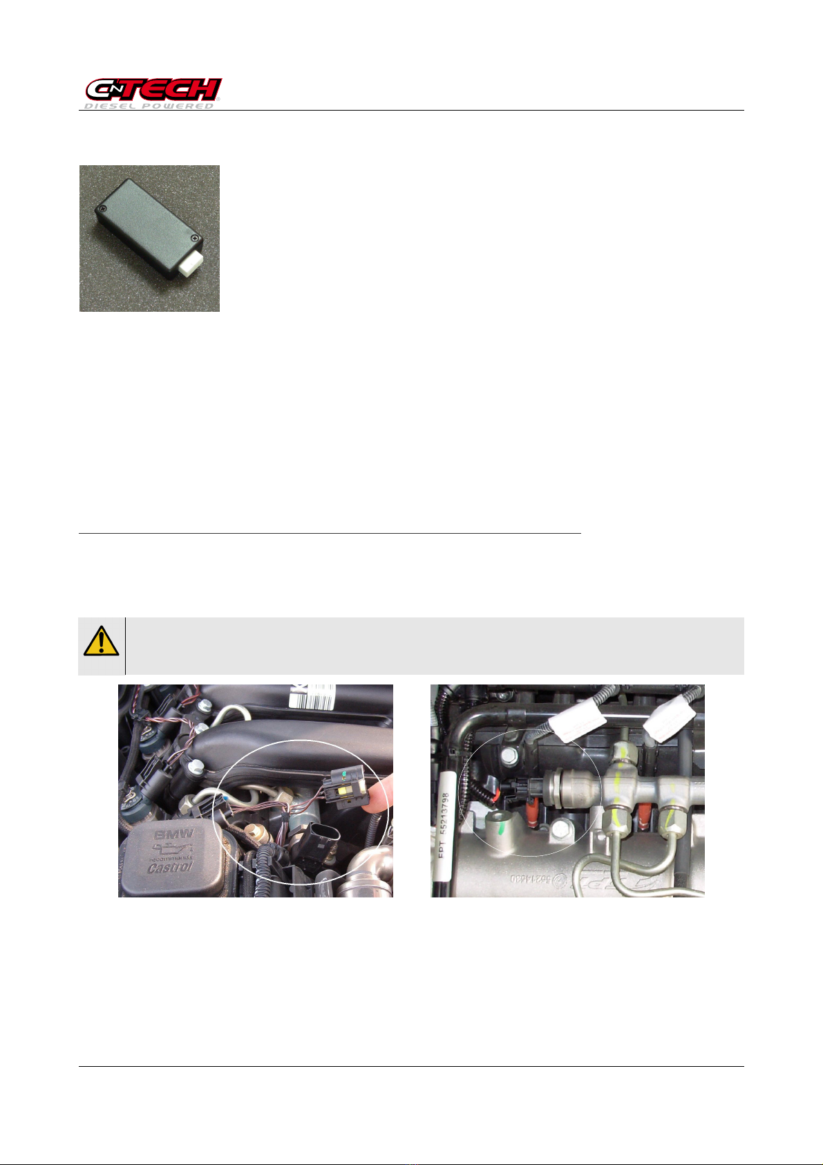
CONNECTING
The CR7 comes with dedicated cabling for engine installation , so all connections are made
quickly without disturbing the original system of the car. The wiring must be connected in
series to the original one of car on the fuel pressure sensor located on the flute high pressure
(R IL). To locate the sensors refer to the supplied photographic instructions.
Feel free to contact us if you are not sure about locating the connectors.
In order to prevent ignition warning indicators when restarting the engine, it is advisable to
remove the key from the ignition and lock the car with the engine compartment open, wait 10
minutes to allow the unit to power off the engine management and only then proceed with the
extraction of the original connector and insertion of the CR7 cabling.
Because of the difficult availability of some connectors, it is possible that they can also
insert in the opposite direction to the correct one. Be VERY careful to insert them
correctly in order to avoid additional problems to the unit or to the injection system.
Example of location of the fuel pressure sensor. Note that the sensor is located directly to the
RAIL duct, from which protrude piping intended to injectors.
08/09/13 CR7-Cablaggio-Istruzioni_vC 1
CR7
www.moduliaggiuntivi.com
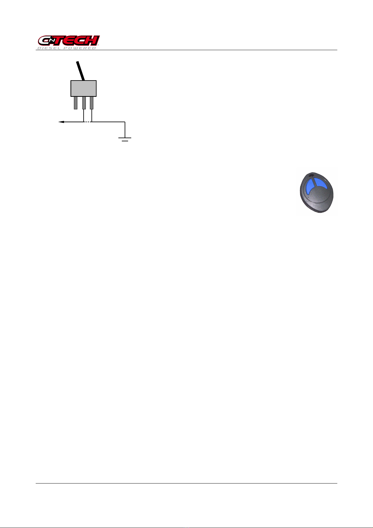
DISABLING SWITCH CONNECTION
The CR7 allows the disabling of the provided increase with a
switch. The power increase is normally enabled and must be
disabled, therefore the connection of this switch is optional.
For connecting this switch, take the GREEN wire derived
laterally from the wiring to GROUND. By interrupting this wire
with a switch you can turn on and off the increase.
Pay attention to toggle this switch only with the accelerator
pedal released or engine off.
NB : If the additional unit CR7 was provided with remote
control, do not consider the above instructions.
USE OF CR7 WITH REMOTE CONTROL
It's possible to combine the control unit CR7 with a 2-button remote control that
allows you to disable or enable the unit.
Operation of the remote control is approximately 5 meters and can be used
comfortably from inside the car.
The unit always stores the last state it was when engine turned off and when
turnig back on it'll recall the last stored.
Each unit CR7 is designed for remote control. It's possible to buy the remote
control KIT, consisting of receiver board to be inserted inside the control unit and remote
control, even after the purchase of the unit.
In remote control KIT instructions are attached to the installation of the receiver board inside
the control unit, an operation that can be done very easily without need for special tools.
08/09/13 CR7-Cablaggio-Istruzioni_vC 2
lla
centralina
I
CR7
www.moduliaggiuntivi.com
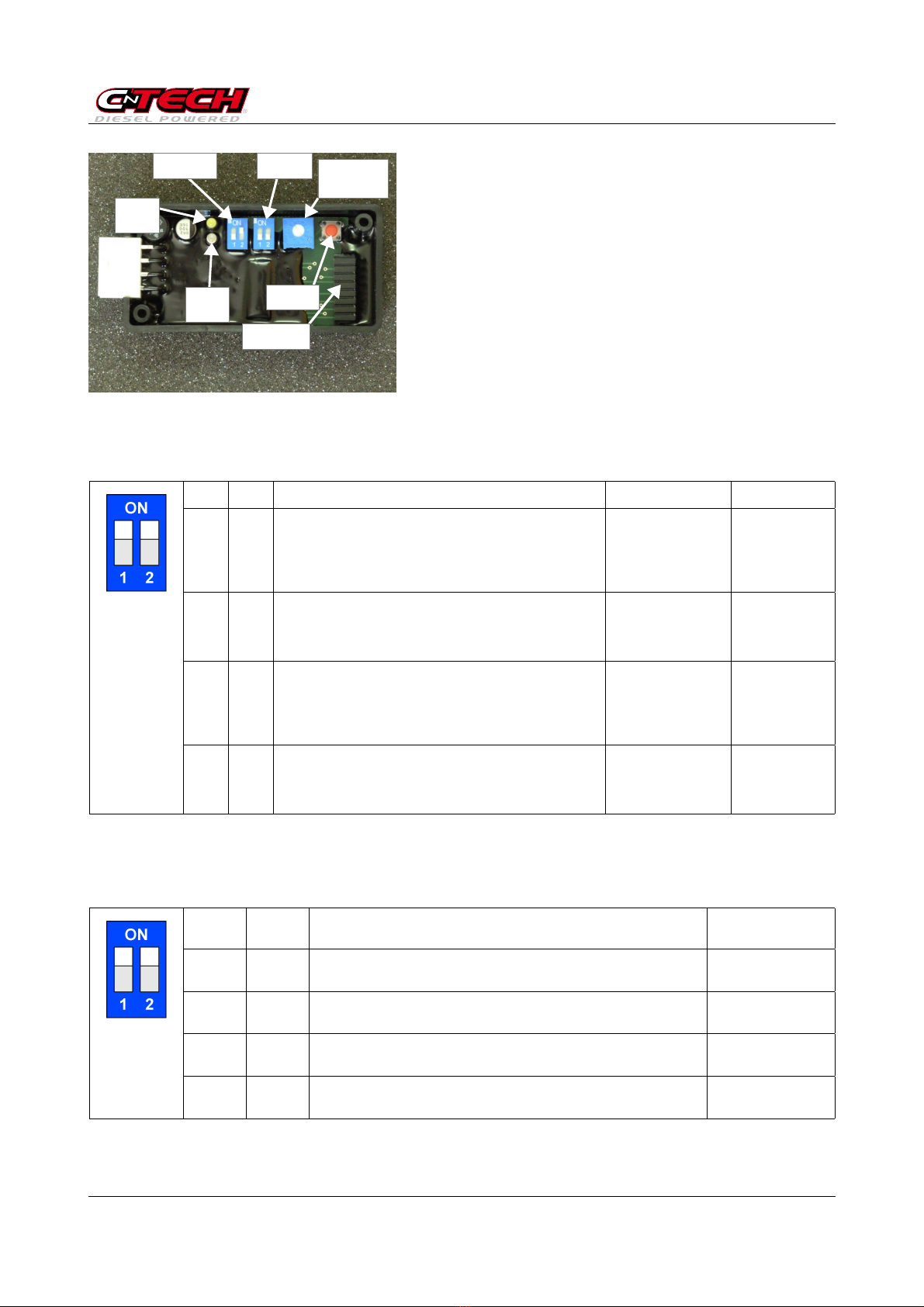
CONFIGURATION
Picture on the left identify the elements that allow
interaction within the additional unit CR7.
Status LED (blue) - This light flashes regularly when
the controller is enabled. When the control is disabled,
the flashing is a short flash..
TX LED (white) - This LED remains off when there is
no receiver board for remote control. In case the
receiver board is present, it flashes after a few second
that has been detected and then blink when you press
a button on the remote.
Maps sele tor - This switch allows you to select the chosen mapping function. You can also
change the setting with engine running. Follow the chart below for the most appropriate
selection.
SW1 SW2 Map RECOMMENDED COMPATIBLE
OFF OFF 1
Map for cars with F P / DPF particularly delicate. If
you have this map recommended do not change
the setting in order to avoid premature clogging of
the filter F P / DPF.
ON OFF 2
Map standards for cars with F P / DPF.
It is also used on cars without F P / DPF in the
case of automatic transmission or work vehicles.
ON ON 3
Map for cars with F P / DPF that have poor
performance with the map 2.
OFF ON 4
Map for cars that do not have filter F P / DPF.
SoftTorque Sele tor - This switch allows you to set the "softness" of the supplied increase. In
some cases you must use the recommended setting for the proper functioning of specific
models.
SW1 SW2 SoftTorque Level RECOMMENDED
OFF OFF 1
BSENT - Providing immediate increase
ON OFF 2
LOW
ON ON 3
MEDIUM
OFF ON 4
HIGH - Providing soft increment.
08/09/13 CR7-Cablaggio-Istruzioni_vC 3
Button
Conf. TX
Maps
sele tor Regulation
in rease
RAIL
Conne tor
RX ard
Sele tor
SoftTorque
LED
TX
(white)
LED
STATO
(blue)
CR7
www.moduliaggiuntivi.com
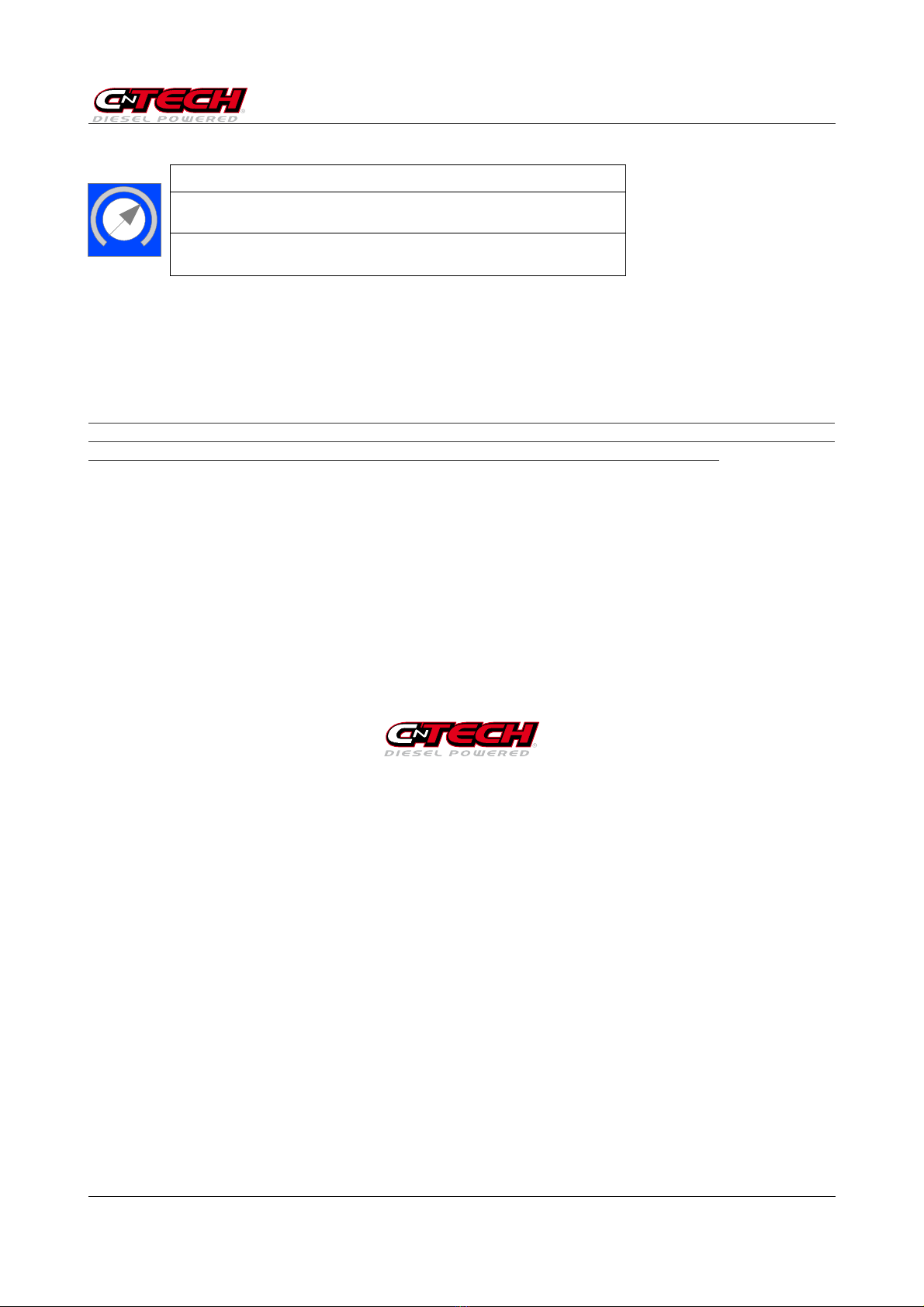
RAIL in rease setting
RAIL STANDARD SETTING
The setting is indicated by overlaying the adjustment screw on the dial of a clock.
Minimum setting: 7 a.m.
Max setting: 5 p.m.
This adjustment allows you to change the R IL power increase provided by the additional unit.
You can not make a direct association between the position of the trimmer and the power
delivered by the engine as these data will vary depending on several parameters. Therefore,
you may want to adjust this trimmer on the road or on a chassis dynamometer for measuring
the power.
Turn the trimmer clockwise, you increase the power. Be careful not to force the adjustment
beyond the area allowed.
Please note that exceeding the increase in power it is possible to find irregularities and cause
ignition fault light to turn on (which is no mechanical or electrical failure). In these cases it is
sufficient to rotate counterclockwise adjustment, turn off and restart the vehicle.
Button Conf. TX
Do not use this button other than to configure a RX card purchased after the unit CR7. In case
of RX card not present is useless, while in case of RX card present configures the remote
controls.
Conne tor RX ard
Connector slot for the receiver card for remote control.
www.moduliaggiuntivi.com
info@moduliaggiuntivi.com
08/09/13 CR7-Cablaggio-Istruzioni_vC 4
Table of contents
Popular Automobile Accessories manuals by other brands


ULTIMATE SPEED
ULTIMATE SPEED 279746 Assembly and Safety Advice

SSV Works
SSV Works DF-F65 manual

ULTIMATE SPEED
ULTIMATE SPEED CARBON Assembly and Safety Advice

Witter
Witter F174 Fitting instructions

WeatherTech
WeatherTech No-Drill installation instructions

TAUBENREUTHER
TAUBENREUTHER 1-336050 Installation instruction