Co-op COMPOST BIN User manual

COMPOST BIN
SIDE VIEWTOP VIEW FRONT VIEW
Pressure Treated
2x2 Baluster, 36"
• 12 boards
Pressure
Treated 2x4, 10-ft.
• 2 boards
Pressure
Treated 1x6, 8-ft.
• 10 boards
4” Strap Hinges
• 4 hinges
#10 Wood Screws,
3/4" long
• 20 screws
Double Hinge Hasp
• 2 hasps
End Cut Wood
Preservatives
• 1 can
5-½" Utility
Door Pull
• 1 pull
DIMENSIONS
home.crs
Coated Deck Screws
• 1¼" long, 64 screws (0.3 lbs.)
• 2" long, 102 screws (0.7 lbs.)
• 3" long, 58 screws (0.6 lbs.)
32¾”
19”
32¼”
341
/
8"
MATERIALS LIST

2
COMPOST BIN CONSTRUCTION
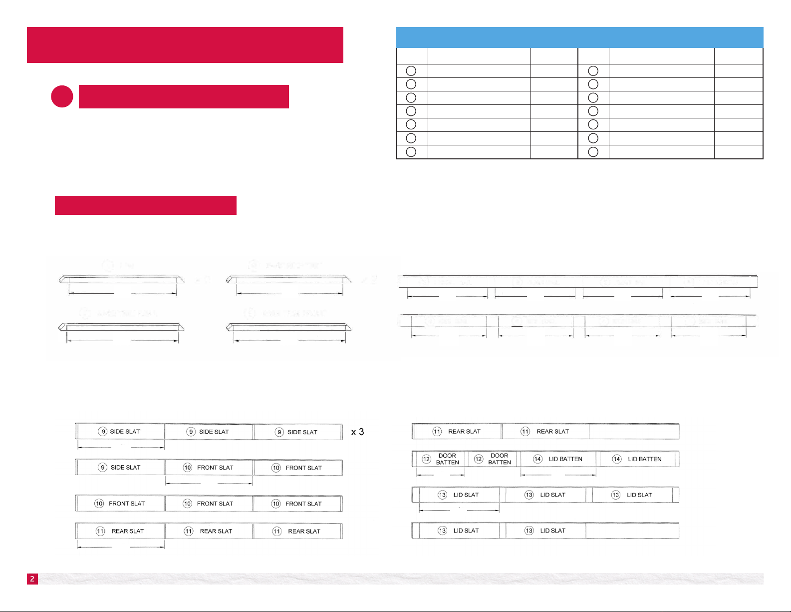
The Cutting Diagrams show how each piece of lumber is to be broken down.
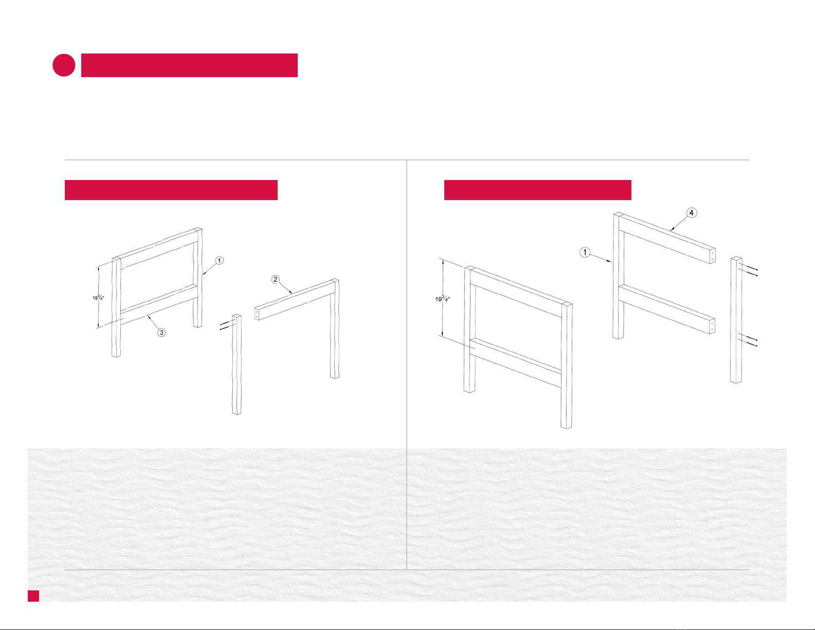
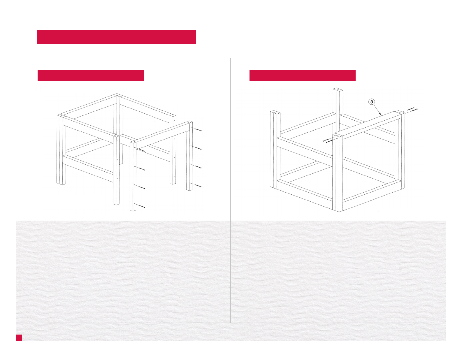
The components are numbered in the order they are assembled. Due to the
moisture that is required for composting, it is highly recommended that all
cuts be treated with an end cut wood preservative.
2x2 Pressure Treated Baluster
Twelve (12) boards 36"long are required for components #1, 6, 7, 8.
1x6 Pressure Treated Lumber
Ten (10) boards 8' long are required for the following components #9 – 14.
2x4 Pressure Treated Lumber
Two (2) boards 10'long are required for components #2 – 5.
CUTTING THE COMPONENTS
1
CUTTING DIAGRAMS
Cutting. Diagrams
2x2 Pressure Treated Baluster
Twelve (12) boards 36"1ong are required for components , @ , ,
x8
2x4 Pressure Treated Lumber
Two (2) boards 1 O' long are required for components -
x2
I
Cutting. Diagrams
2x2 Pressure Treated Baluster
Twelve (12) boards 36"1ong are required for components , @ , ,
x8
2x4 Pressure Treated Lumber
Two (2) boards 1 O' long are required for components -
x2
I
Cutting. Diagrams
2x2 Pressure Treated Baluster
Twelve (12) boards 36"1ong are required for components , @ , ,
x8
2x4 Pressure Treated Lumber
Two (2) boards 1 O' long are required for components -
x2
I
COMPONENTS LIST
# Component Name Quantity # Component Name Quantity
1 Leg 8 Base Trim Front 1
2 Front Rail 1 Side Slat 10
3 Rear Rail 2 Front Slat 5
Side Rail 4 Rear Slat 5
Threhold 1 Door Batten 2
Base Trim Side 2Lid Slat 5
Base Trim Rear 1 Lid Batten 2
10
9
8
3
6
13
7
14
2
5
12
1
4
11
32¾"
31½" 311
/
8"
251
/
8"
311
/
8"
251
/
8" 251
/
8" 251
/
8"
32¾"
31¼"
28¾"
17¼" 27"
31¼"
26¾" 26¾" 26¾" 26¾"

ASSEMBLE THE COMPONENTS
2
NOTE:
• lt is good practice to drill clearance and pilot holes before installing
screws in narrow boards or near the end of a board.
Doing so makes it easier to align and assemble the joint, increasing its strength,
and reducing the chance of splitting the wood.
1.1 Connect the Legs (1) to the Front Rail (2) and the Rear Rails (3) as shown.
1.2 All connections are made with 3" Deck Screws.
•Connect the Legs (1) to the Side Rails (4) with 3" Deck Screws as shown.
STEP 1. FRONT AND REAR FRAME ASSEMBLY STEP 2. SIDE FRAME ASSEMBLIES
3
3” Deck Screws - 12 3” Deck Screws - 16

3” Deck Screws - 4
COMPOST BIN ASSEMBLY (continued)
4.1 Turn the frame assembly upside down and position the Threshold (5)
flush with the front and bottom edges of the front legs.
4.2 Secure the Threshold with 3" Deck Screws.
STEP 4. INSTALL THE THRESHOLD
4
•Connect the front and rear leg assemblies to the side assemblies
with 3" Deck Screws.
STEP 3. BIN FRAME ASSEMBLIES NOTE:
• The orientation of the front,
rear, and side assemblies is
critical.
• The screws are driven through
the front and rear assemblies
into the sides.
3” Deck Screws - 16

COMPOST BIN ASSEMBLY (continued)
STEP 6. ATTACH THE TOP SLATS
5.1 Position the Base Trim Side (6) as shown and secure with 3" Deck Screws.
5.2 lnstall the Base Trim Rear (7) as shown and secure with 3" Deck Screws.
5.3 Secure the Base Trim Front (8) as shown with 3" Deck Screws.
5
2” Deck Screws - 24
3/4” Projection
Ends are ush
3" Deck Screws - 10
6. Working down from the top of the frame assembly, attach the Side
Slats (9) to the frame assembly as shown.
6. Attach the Front Slat (10) and Rear Slat (11) to the frame assembly
as shown.
6. Secure all slats with 2" Deck Screws.
STEP 5. TRIM THE BASE NOTE:
• The top slats should project 3/4" above
the top of the frame assembly.
• The side slats are installed first. The ends
should sit flush with the back and front
of the frame assembly.

6
1¼" Deck Screws - 24
2" Deck Screws -78
3/4" Spacer
4¾"
Framing Square
Spacer Block
3/8"
COMPOST BIN ASSEMBLY (continued)
8.1 Place the three remaining Front Slats (10), best face down, on a flat surface.
8.2 Use 3/4" spacer blocks to maintain consistent gap spacing and square
the boards.
8.3 Place the Door Battens (12) across the slats as shown and secure with
1¼" Deck Screws.
7. Working from the top down, use 3/4" spacer to position each slat.
7. Secure the slats to the frame assembly with 2" Deck Screws.
STEP 7. ATTACH THE SLATS STEP 8. DOOR ASSEMBLY
NOTE:
• Only two (2) slats are installed
on the front of the bin.

COMPOST BIN ASSEMBLY (continued)
10.1 Attach 4" Strap Hinges to the rear of the bin as show with #10 x 3/4"
Wood Screws.
10.2 Attach 4" Strap Hinges to the front of the Door as shown with #10 x 3/4"
Wood Screws.
10.3 Attach the Double Hinge Hasp as shown with the screws provided.
Do NOT install the hasp staple at this time.
STEP 10. ATTACH THE HNGES AND HASP
7
Double
Hinge Hasp
4" Strap Hinge
9. Place the Lid Slats (13), best face down, on a flat surface.
9. Use 3/4" spacer blocks to maintain consistent gap spacing and square
the boards.
9. Place the Lid Battens (14) across the slats as shown and secure with
1¼" Deck Screws.
STEP 9. LID ASSEMBLY
1½"
1¾"
20¼"
5½"
5½"
Framing Square 1¼" Deck Screws - 40
4" Strap Hinge - 4
Double Hinge Hasp -2
#10 x 3/4" Wood Screws -12

COMPOST BIN ASSEMBLY (continued)
NOTES
8
11. Center the lid on the bin and secure the hinge leaves to the lid with
#10 x 3/4" Wood Screws.
11. Center the door in its opening and secure the hinge leaves to the bin
with #10 x 3/4" Wood Screws.
11. Secure the Hasp Staple with the screws provided.
11. Attach the Handle with the screws provided.
STEP 11. ATTACH THE LID, DOOR, HANDLE AND STAPLES
Staple
#10 x 3/4" Wood Screws - 8
5½" Door Pull - 1
Hasp Staple - 2
NOTE:
• Only 2 screws are used on each
hinge leaf.
• Screws are NOT placed in the
holes located next to the hinge
barrel.
Disclaimer: In addition to the Terms of Use found at www.fcl.crs/contact-us/privacy-terms, you are responsible for any applicable code approval or permits associated with
the construction and use of this plan. Check with a building-code official or a building expert to make sure that the materials and construction methods shown meet local
codes and conditions and are suitable to your situation. It is the responsibility of the builder to ensure the proper tools, measurements, cuts and building techniques are used
in the construction of this plan. CO-OP®assumes no responsibility for the incorrect use of this information. Please ensure the manufacturer's instructions are followed in the
use of all tools and materials and heed all recommended safety guidelines.
®CO-OP and design trademark are registered trademarks of Federated Co-operatives Limited, Saskatoon S7K 3M9
Table of contents