2. - Contents
HRB202-202S-252D-302D
7
KN136JGB_D
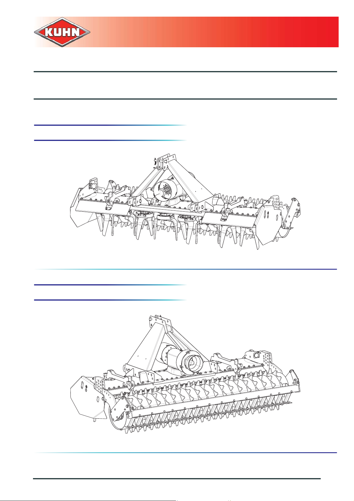
Power harrow
9.6 Track eradicators with traction bolt or spring overload mechanism (HRB302D) ........................... 95
9.6.1 Uncoupling the machine................................................................................................... 96
9.6.2 Adjustments in working position....................................................................................... 96
9.6.3 Safety............................................................................................................................... 97
9.6.4 Maintenance..................................................................................................................... 98
9.7 Front or rear levelling bar .............................................................................................................. 98
9.7.1 Adjustments in working position....................................................................................... 98
9.8 Lights and indicators.................................................................................................................... 100
9.8.1 Coupling and uncoupling................................................................................................ 100
9.9 Lateral signalling equipment........................................................................................................ 100
9.9.1 Instructions specific to France........................................................................................ 100
9.10 Front signalling elements (HRB252D-HRB302D)........................................................................ 101
9.10.1 Coupling and uncoupling................................................................................................ 101
9.11 USA signalling equipment ........................................................................................................... 101
9.12 Retractable side deflectors (HRB252D-HRB302D)..................................................................... 102
9.12.1 Coupling and uncoupling................................................................................................ 102
9.12.2 Maintenance................................................................................................................... 103
9.13 Universal arm kit (HRB252D-HRB302D)..................................................................................... 104
9.14 32X38-8 spline yoke (HRB252D-HRB302D)............................................................................... 104
9.15 Adaptation parts for VENTA LC (HRB302D) ............................................................................... 105
10. Maintenance and storage.......................................................................................... 106
10.1 Frequency chart........................................................................................................................... 106
10.2 Cleaning the machine.................................................................................................................. 107
10.2.1 Packer PK2 roller: (a)..................................................................................................... 107
10.2.2 Maxipacker roller: (b)...................................................................................................... 107
10.3 Lubrication................................................................................................................................... 108
10.3.1 Primary PTO shaft.......................................................................................................... 108
10.3.2 Trough.............................................................................................................................110
10.3.3 Draining...........................................................................................................................110
10.3.4 Greasing..........................................................................................................................113
10.4 Maintenance.................................................................................................................................114
10.4.1 Gearbox oil level check...................................................................................................114
10.4.2 Checking the blades and their mounting hardware.........................................................114
10.5 Storage.........................................................................................................................................118
10.5.1 At the end of each season...............................................................................................118
10.5.2 At the start of each season..............................................................................................119
10.5.3 Storage............................................................................................................................119
10.6 Dismantling and scrapping of the machine.................................................................................. 120
11. Troubleshooting guide .............................................................................................. 121