INSTALLATION NOTES
ORDER OF INSTALLATION
For ease of installation we recommend the
following installation sequence:-
1/ Header Tank(s)
2/ Water / Plumbing
3/ Set Up Water Cylinders
4/ Install Airlines
5/ Controllers and Electrical
WATER / CHEMICAL
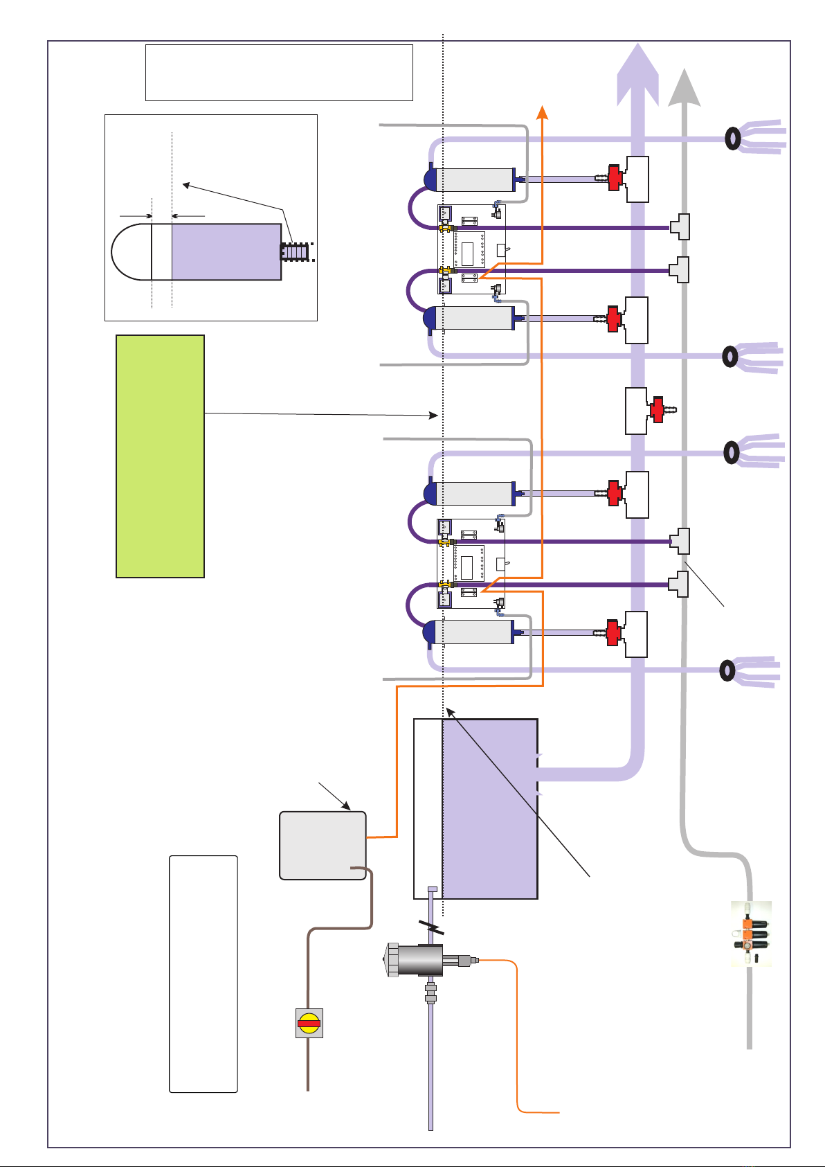
Site the Header Tank at the same level as the
cylinders. Ensure that the water level in the
cylinders is set 50mm (2 inches) below the top
of the stainless tube, (see drawing opposite).
Run 2 inch (50mm) water tube from header tank
along the centre of the parlour, connecting to
every cylinder using tees, taps and 10x16mm
i/d tube. Terminate this tube with a reversed
(upside-down) tee/tap so that it can be used as
a drain point if required.
Chemical Dosing
We can supply Dosatron high accuracy dosing
units if required. When dealing with chemicals,
do take all recommended precautions. Before
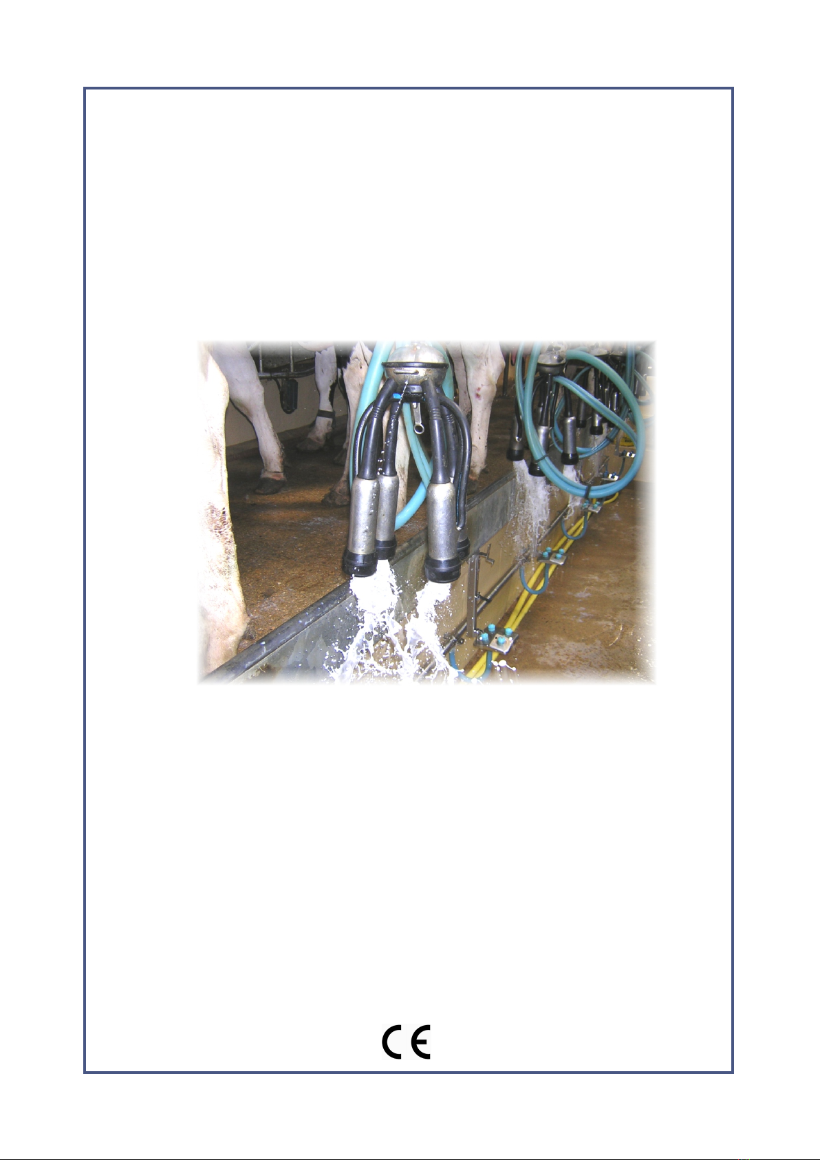
commissioning the system, ensure all unions
are tight and the clusters hang correctly
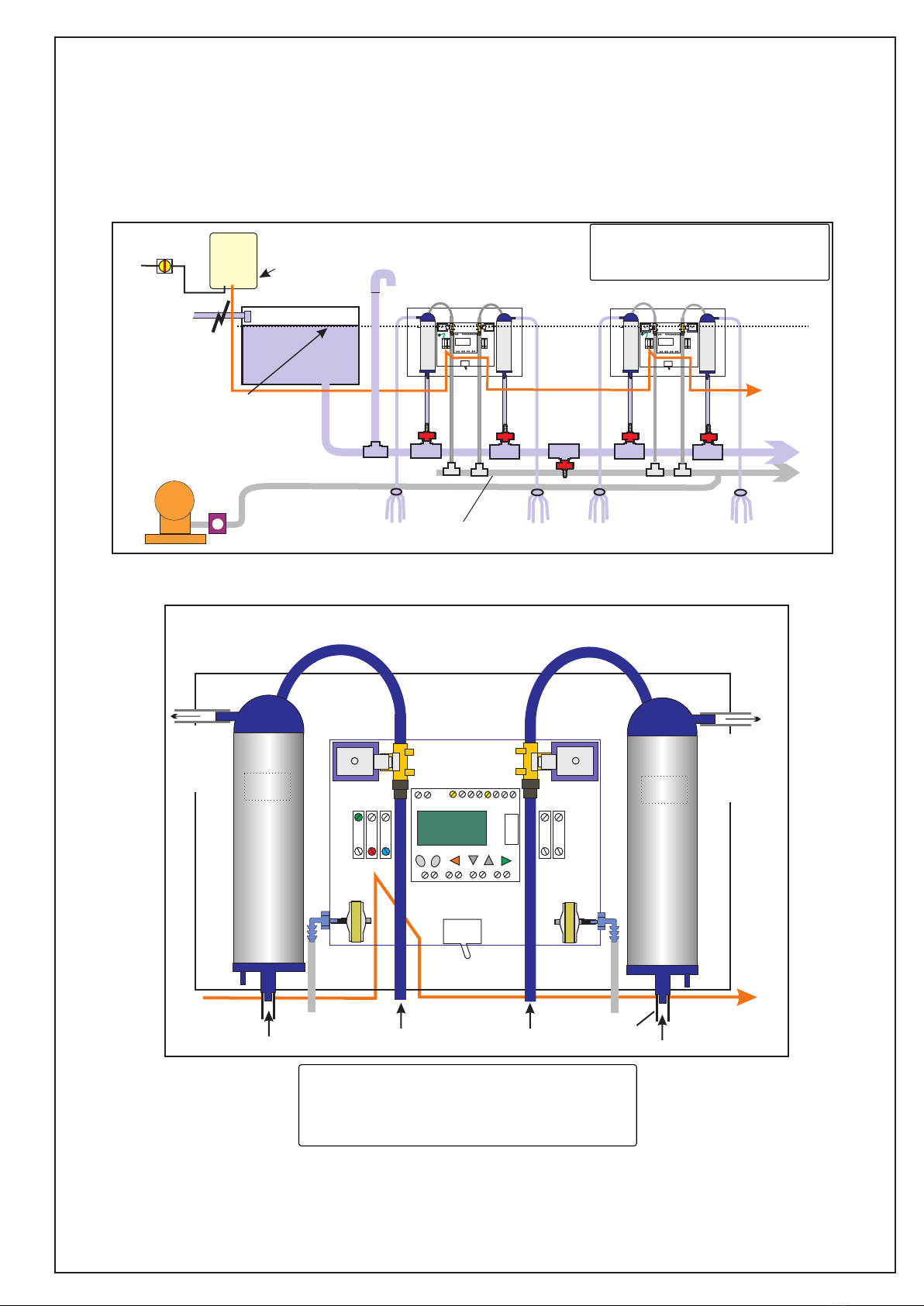
Schematic Top View
disposition of system components for
swing-over parlour
HEADER
TANK
COMPRESSOR
MAINS ISOLATOR
SWITCH
PSU
AIR 24v DC WATER
CONTROLLERS
CONTROLLERS
CONTROLLERS
AIR 2 - 3 bar, (pressure reducer may be
required)
Use 22mm Flexible Tubing between the
compressor (clean air filters should be fitted)
and the first 22x22x10mm tee located adjacent
to the first controller. Continue to following
controllers using rigid tubing. Terminate the air
line in a blanking cap.
Anti-Syphon Valves
fit one valve either side of the Tee connection of air line, at the mid-point of each half (see schematics)
Pressure Reducer
Cotswold can supply a suitable pressure reducing valve if required.
ELECTRICAL
Install Power Supply Unit (PSU) in a safe dry location adjacent to the dairy, run 24v supply to first controller,
and then daisy-chain the supply from controller to controller.
Each controller controls two milking points simultaneously.
Arrange a conveniently located switch to turn off the system when not in use.
Always switch off system when washing-down the parlour
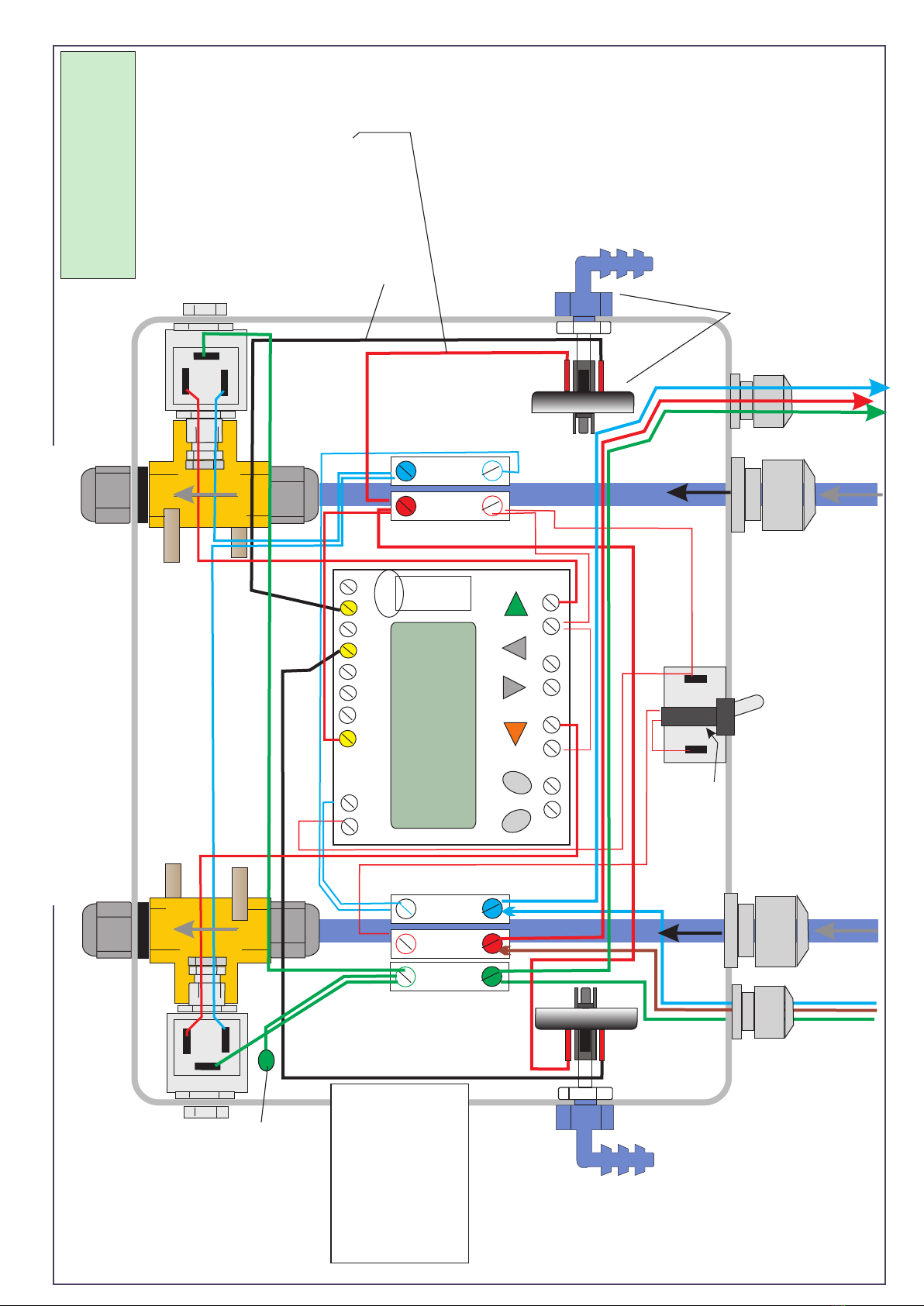
CONNECTION TO MILK LINE
Cut into the milk line and fit the “Y” piece moulding using 13mm pvc tubing connecting to upper
horizontal outlet of stainless steel pressure cylinder.
= Anti Syphon
Valve
AIR
WATER
24v
6