Co2meter CM-7000 User manual

USER MANUAL
Multi CO2 Sensor System
CM-7000

2 | P a g e
Contents
Product Overview ...................................................................................................................................4
The device includes the following key features:.............................................................................4
Components ...........................................................................................................................................5
Accessories .............................................................................................................................................5
System Specifications.............................................................................................................................6
System Electrical/Mechanical.............................................................................................................6
Dimensions..........................................................................................................................................6
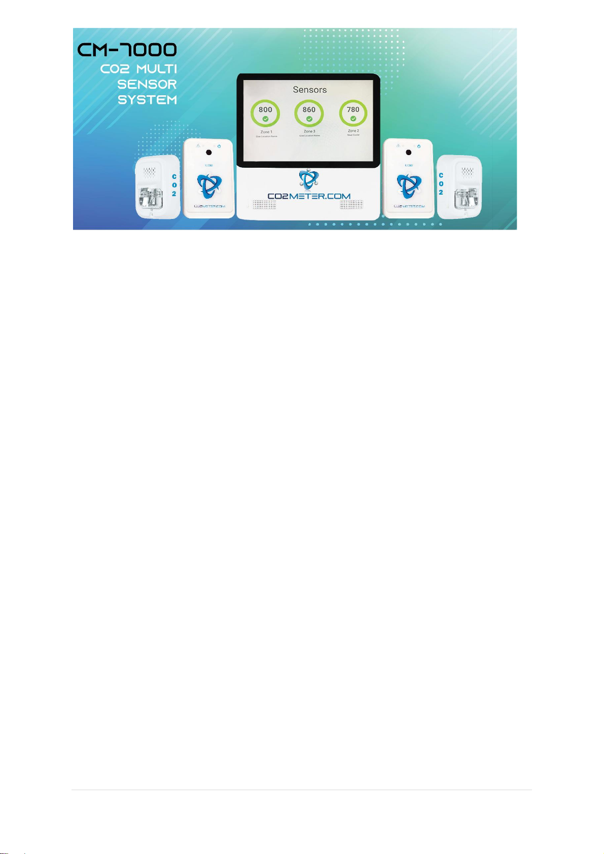
CM-7005 Main Tablet .........................................................................................................................6
CM-7003 CO2 Sensor..........................................................................................................................6
CM-7004 Horn Strobe.........................................................................................................................6
CM-7002 Remote................................................................................................................................6
CBL-7002 .............................................................................................................................................7
CM-7006..............................................................................................................................................7
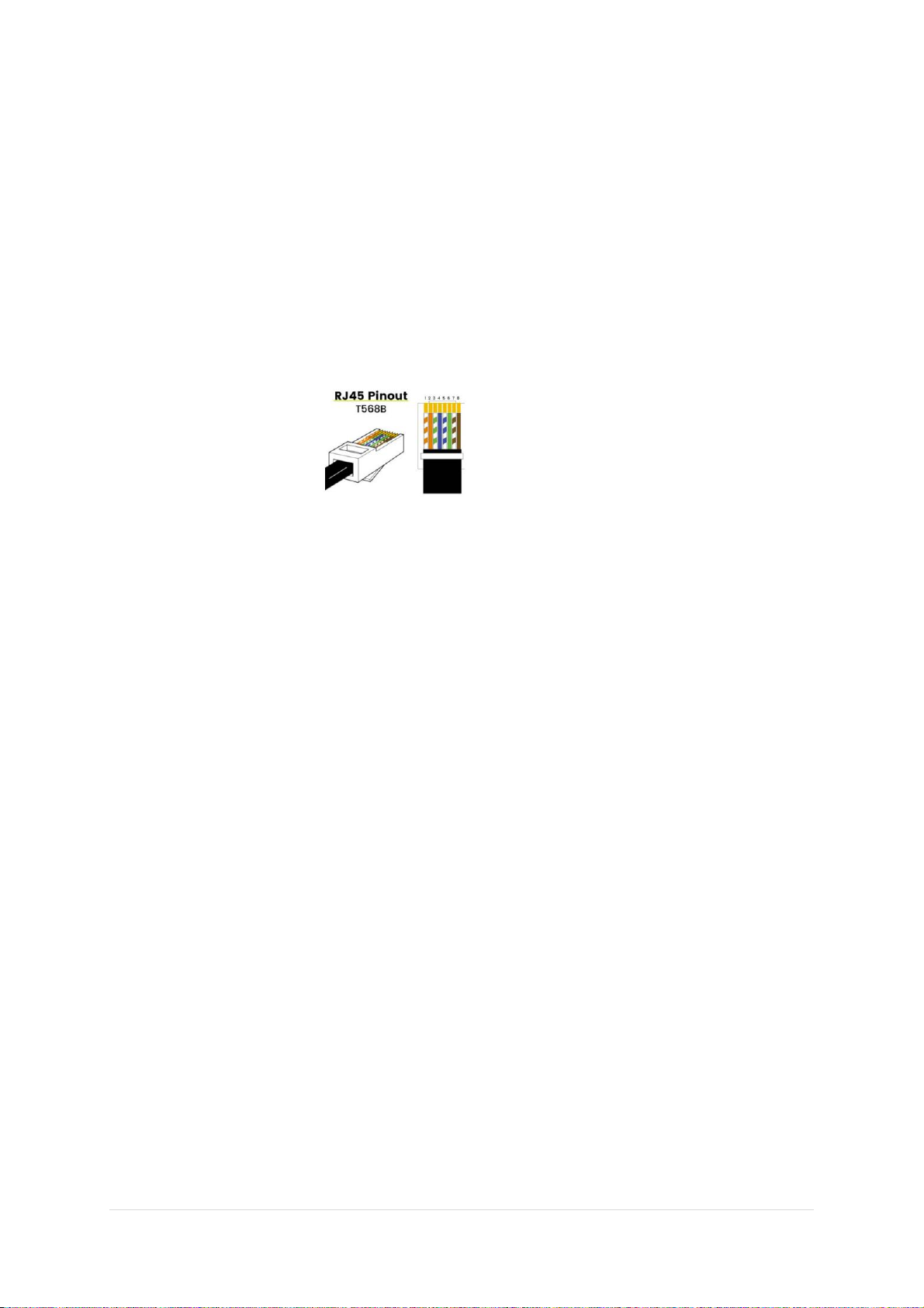
CAT5e Cables.......................................................................................................................................7
CM-7009 POE Injector.........................................................................................................................7
CM-1026-6 Strobe Tower....................................................................................................................7
CM-1026-5 Strobe Tower....................................................................................................................7
SV-1029/30 .........................................................................................................................................7
Installation..............................................................................................................................................8
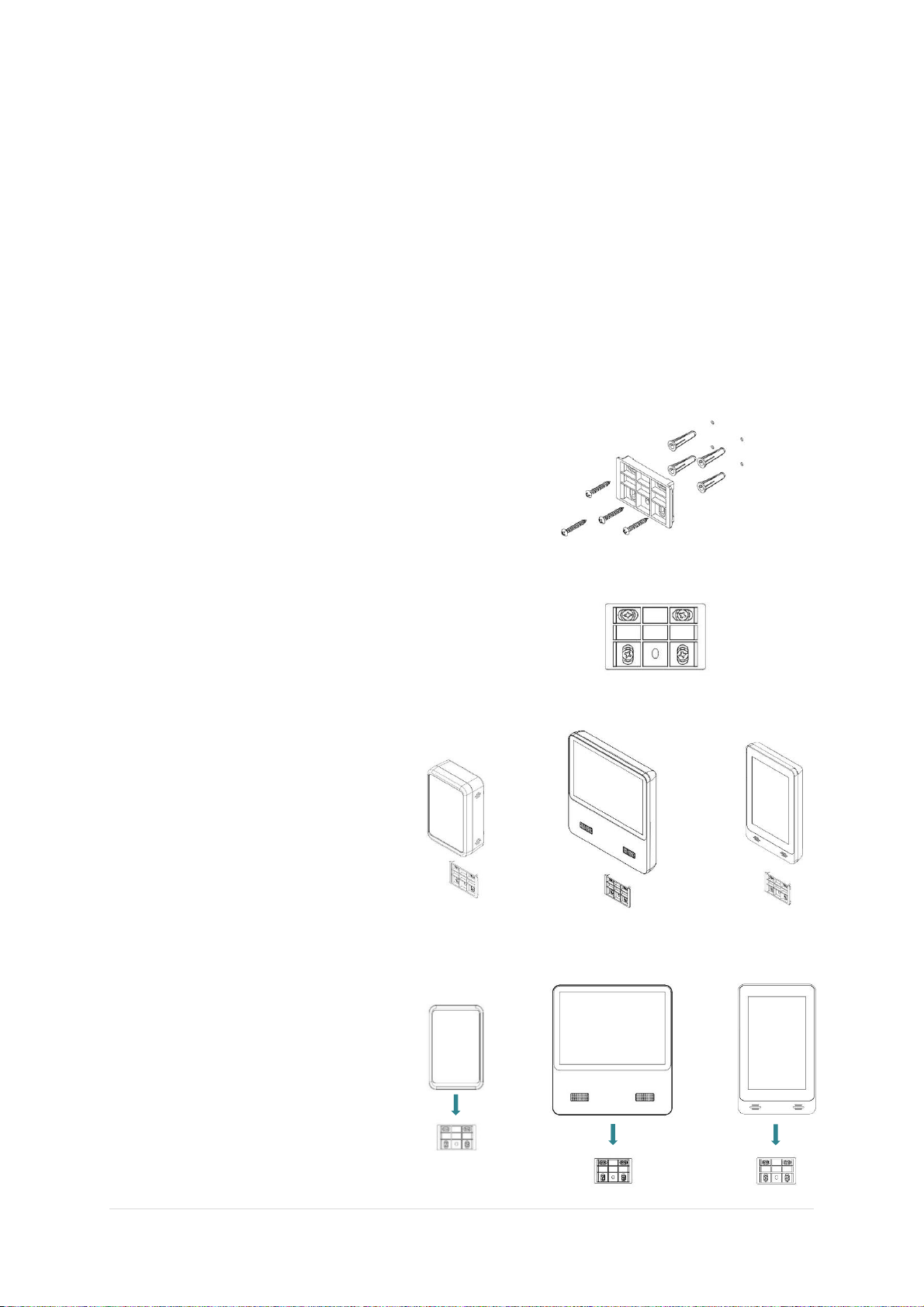
Wall Mounting Instructions: ...............................................................................................................8
CM-7005 Main Tablet, CM-7003 Sensor, CM-7002 Remote, and CM-7006 Mini Display Tablet...8
Tablet Installation ...............................................................................................................................9
CM-7003 Sensor Unit Installation.......................................................................................................9
HornStrobe Installation.....................................................................................................................10
CM-7002 Remote Installation...........................................................................................................10
CM-7000 System Installation DO’s and DON’Ts..................................................................................11
Installation DOs.................................................................................................................................11
Installation DON’Ts ...........................................................................................................................11
Displays Explained................................................................................................................................12
Main Sensors Page........................................................................................................................12
Main Groups Page (Without any Groups Create).........................................................................12
Main Groups Page (With Groups Create) .....................................................................................12
Individual Sensor Page..................................................................................................................13
Individual Remote Page ................................................................................................................13
System Settings Page ....................................................................................................................14

3 | P a g e
Individual Group Page...................................................................................................................15
Group Alarm Settings........................................................................................................................15
Operation..............................................................................................................................................16
Verify Firmware Version ...................................................................................................................16
Unlocking Tablet ...............................................................................................................................17
Option 1: Unlock from System Settings Page ...............................................................................17
Option 2: Unlock from the Sensor Page........................................................................................18
Adjusting Alarm Settings...................................................................................................................19
..........................................................................................................................................................19
Group Configuration .........................................................................................................................20
Creating Group..............................................................................................................................20
Adding Sensors to a Group ...........................................................................................................21
Adjusting Group Settings ..............................................................................................................22
Relay Operation and Connection (CM-7005 & CM-7002) ................................................................23
Tablet Relay Operation .................................................................................................................23
Tablet Relay Connection ...............................................................................................................23
Remote Relay Operation...............................................................................................................24
Remote Relay Connection (CBL-7002)..........................................................................................24
Calibration.............................................................................................................................................25
Safety Notice.........................................................................................................................................26
Product Care .........................................................................................................................................26
Support .................................................................................................................................................27

4 | P a g e
Product Overview
Thank you for selecting the CM-7000 CO2 Multi Sensor System.
High concentrations of carbon dioxide in confined spaces are dangerous and may lead to
negative health problems, including headaches, fatigue, asphyxiation or possibly fatality.
The CM-7000 series features multiple gas sensors connected to a main control panel. The
device is designed to detect Carbon Dioxide (CO2) levels in the ambient air to protect
employees, workers, and facilities.
The CM-7000 features a multitude of sensor configurations with the option of pairing
programmable relays. These relays are preset to be triggered at 5,000ppm TWA,
5,000ppm, 1.5%, and 3% to meet OSHA/NIOSH standards. This system was designed to
adhere to local fire codes in regard to CO2 safety monitoring.
With the CM-7000, you and your employees are safe and protected.
The device includes the following key features:
•Full color, 8" TouchscreenDisplay
•Expandable Sensor Array with up to 12 sensors + horn strobes (Expandable up to
60 Sensors with the assistance of a CM-7000 Specialist)
•Measures 0-5% CO2
•Individually addressable sensors and groups
•User configurable settings
•Selectable alarms ranging from 5000ppm TWA, 5000ppm, 1%, 1.5%, 2%,
2.5%, 3%, 3.5%, 4% (configurable)
•Lock/unlock code for complete system security
•Audible/Visual Alarms

5 | P a g e
Components
CM-7000 –CO2 Multi Sensor System - The system includes a main tablet and
sensor/s paired with other components for alarm and relay function.
CM-7001 - Sensor and Horn/Strobe Combo Package - The Sensor and
Horn/Strobe Combo Pack provides additional sensing capabilities for customers who
require additional sensors and strobes per industry or application. (Discontinued)
CM-7002 - Remote Relay Key Switch - The Remote Relay Key Switch unit
provides a unique push-button and key switch to mute and reset latch for all sensors
in a group.
CM-7003 - CO2 Sensor Unit –The CO2 sensor unit designed to detect Carbon
Dioxide anywhere it is stored or used in manufacturing.
CM-7004 - Horn Strobe - Additional Horn/Strobes can be purchased per industry or
application dependent upon customer needs and requirements. Amber lens is
included, blue lens is available for purchase.
CM-7004-OUT - Outdoor Horn Strobe - Additional outdoor Horn/Strobes can be
purchased per industry or application dependent upon customer needs and
requirements. Amber lens is included, blue lens is available for purchase.
CM-7005 - Main Tablet Only - 8”-inch touch screen control panel.
CM-7006 -Mini Display Tablet –The secondary tablet designed for remote display
only. The gas readings and safety alarm status mirror to this display for viewing
purposes. *Note: The CM-7006 is for viewing only. This tablet does not offer control
of the system.
CM-7009 - POE Power Injector- Secondary POE injector used to increase the
power capabilities of the CM-7000 system. Has the ability to increase the quantity of
add-ons and the length of daisy chains.
Accessories
CBL-7002 - Reset Unit Relay Cable - The relay cable provides ease of access and
connection to the relays housed in the CM-7002 Remote unit. This cable can be
used to wire to the CM-1026-5,6 Strobe Towers and SV-1029Solenoid Valve.
CM-1026-5/CM-1026-6 - CO2 Storage Safety Strobe Tower- designed to provide a
flashing indicator, and audible alarm with any of our CM-7000 systems.
SV-1029-3/8 in. Solenoid Safety Shut Off Valve - designed to be utilized with
our CM-7000 CO2 Multi-Sensor System, and can be directly wired to the
SV-102924VDC safety shut-off valve via main tablet or sensor unit relays.
ADP-7000 –Replacement Power Supply –In the event of damage to the included
CM-7005 power supply. The ADP-7000 is the required replacement.
SV-1030 -1/2 in. Solenoid Safety Shut Off Valve - designed to be utilized
with our CM-7000 CO2 Multi-Sensor System, and can be directly wired to the
SV-102924VDC safety shut-off valve via main tablet or sensor unit relays.

6 | P a g e
System Specifications
System Electrical/Mechanical
•Power Input: 48-58VDC
•Power Consumption: 3-30W
•Power Consumption: 300mA peak, 30mA average
Dimensions
•CM-7005 (Main Tablet): 8.0" w x 8.75" l x 1.5" h (Screen is 8" LCD touchscreen)
•CM-7002 (Remote Unit): 3.5" w x 5.5" l x 1.75" h
•CM-7003 (Sensor): 3.5" w x 5.5" l x 1.75" h
•CM-7004 (Horn Strobe): 5.5" w x 4.5" l x 2.75" h
•CM-7006 (Mini Display Tablet): 5" w x 8.3" l x 2.75 " h
CM-7005 Main Tablet
•8”Capacitive Touchscreen
•(QTY-2) 1 Watt Speakers
•48-54V DC Power Input
•(QTY-4) CAT5 Powered Ethernet Connector Ports
•CAT5 Un-Powered Uplink Ethernet Connector (Used for Troubleshooting Only)
•USB Type A Connector (Used for Troubleshooting and Updates Only)
•(QTY-3) 10A Relays
CM-7003 CO2 Sensor
•CO2 Measurement: Non-Dispersive Infrared (NDIR)
•CO2 Measurement Range: 0-5% (400-50,000ppm)
•Measurement Interval: 2 seconds
•Response time: 90% at 2 minutes
•Sensor Reading Frequency: 0.5Hz
•Sensor Life Expectancy: > 15 years
•Maintenance Interval: Annual Zero Calibration
•Connections: Input / Output / Strobe - CAT5 8 pin Connector
CM-7004 Horn Strobe
•110 Candela Amber Strobe
•90-120dB 3KHz Temporal Horn
•Dual CAT5 Connector
•6 ft CAT5e Cable
CM-7002 Remote
•Mute Push Button
•System Reset Lock Switch
•(QTY-3) 2A Relays
•25 ft CAT5e Cable
•Connections: Input / Output / Strobe - CAT5 8 pin Connector

7 | P a g e
CBL-7002
•Screw terminal adapter cable
•End 1: RJ45 Male
•End 2: 8 Position Screw terminal Connector
CM-7006
•7” Vertical Capacitive Touchscreen
•(QTY-1) CAT5 Powered Ethernet Connector Ports
•USB Type A Connector (Used for Troubleshooting and Updates Only)
CAT5e Cables
•25ft length
•6ft length
•T568B RJ45 Pinout
CM-7009 POE Injector
•Input:100-240VAC 50/60Hz
•Tablet Input: 48V 1.0A
•Data Rate: 10/1000Mbps
CM-1026-6 Strobe Tower
•24 V DC
•6’(2m) Cable included
•Length: 11.5" long
•Diameter: each 1.5"
•Alarms set to match 3 relays on RAD units (user configurable)
•Mounting bracket include
CM-1026-5 Strobe Tower
•100-240AC
•6’(2m) Cable included
•Length: 16" long
•Diameter: each 1.5"
•Alarms set to match 3 relays on RAD units (user configurable)
•Mounting bracket include
SV-1029/SV-1030
•Pipe Size: 3/8 or 1/2 in.
•Max Operating Pressure: 130 psi
•Body Material: Brass
•Length: 1-15/64” xWidth: 1-11/16”x Height: 2-51/64”
•IP Rating: 65
•UL Approved
•24VDC

8 | P a g e
Installation
*** WARNING ***
Please carefully follow this instruction in order for a successful installation. If these instructions are
not properly followed during installation, there is a high-risk additional troubleshooting will be
required or system failure will occur.
*** WARNING ***
Wall Mounting Instructions:
Mount all parts of the CM-7000 system in place prior to wiring. Once all components are mounted
in place, proceed to wiring.
CM-7005 Main Tablet, CM-7003 Sensor, CM-7002 Remote, and CM-7006 Mini Display Tablet
Step 1:
Use the included wall bracket to mark hole
locations. Be sure to use included wall anchors
for a secure mount.
Step 2:
Install the bracket on the wall using all 4
anchors and all 4 screws intended for the
bracket. Level before completely tightening to
the wall.
Step 3:
The same wall bracket is used for
the CM-7002, CM-7003, CM-7005
and CM-7006. These components
slide over the bracket to lock in
place.
Step 4:
Simply center the component over
the bracket, press against the wall,
then slide the unit down until it
locks into place.
To remove from the bracket, simply
slide up in the opposite direction.

9 | P a g e
*** WARNING ***
Please carefully follow this instruction in order for a successful installation. If these instructions are
not properly followed during installation, there is a high-risk additional troubleshooting will be
required or system failure will occur.
*** WARNING ***
Tablet Installation
* Please Note: The Tablet Mounting Bracket should be installed at eye level, outside the
location of CO2.
Step 1. Follow wall mounting instructions previously mentioned.
Step 2. Plug green screw terminal power connector into Tablet and secure with screws.
Step 3. Slide the CM-7005 8" tablet onto the mounting bracket.
Step 4. Plug the Power Adapter into an Outlet and verify the Tablet turns ON.
Step 4. Begin daisy chain connection of CM-7003 and CM-7002 units. Connect them ONE AT A TIME
using port 1-4 on the back of the tablet. (See diagram on page 10)
Back of CM-7005
***DO NOT MOVE ON TO CONNECT THE NEXT UNIT UNTIL THE PREVIOUS IS DISPLAYED ON THE
MAIN SENSOR PAGE OF THE TABLET***
CM-7003 Sensor Unit Installation
* Please Note: The sensor unit should be mounted 12". off the floor, near the CO2 source.
* Please Note: The maximum distance (Cable Length) a unit can be placed from the tablet is 250’.
* Please Note: Connect Sensors to tablet one at a time while tablet is powered.
Step 1. Follow wall mounting instructions previously mentioned.
Step 2. Connect Ethernet cable from Tablet port 1-4 to Senser Unit "Input" port.
Step 3. Green LED power indicator will activate on the Sensor Unit.
Step 4. Wait for Sensor to display on Main Sensor Page of the tablet.
Step 5. Press Sensor Unit against the wall, slide the unit down until it locks in place on the bracket.
Step 6. Name Senor on Tablet

10 | P a g e
HornStrobe Installation
* Please Note: This Mounting Bracket is designed to be mounted on junction boxes if needed.
Step 1. Remove Mounting Bracket, from back of horn strobe assembly.
Step 2. Mount the Horn Strobe Bracket to the wall.
Step 3. Place the CAT5 cable in bottom port hole of the mounting bracket.
Step 4. Slide the front horn strobe cover to mounting bracket.
Step 5. Secure bracket and the horn strobe cover together with a tamper proof screw.
Step 6. Install Ethernet Cable to the Sensor Unit "Strobe" port.
CM-7002 Remote Installation
* Please Note: Not included in standard CM-7000 Package
Step 1. Follow wall mounting instructions previously mentioned.
Step 2. Connect Ethernet cable from Tablet port 1-4 to Remote Unit "Input" port.
Step 3. Green LED power indicator will activate on the Remote unit.
Step 4. Wait for the Remote to display on Main Sensor page of the tablet.
Step 5. Press Remote against the wall, slide the unit down until it locks in place on the bracket.
Step 6. Name Remote on Tablet
Example:

11 | P a g e
CM-7000 System Installation DO’s and DON’Ts
Installation DOs
•DO Power on the CM-7005 Main tablet prior to connecting CM-7003 Sensors or CM-7002 Remotes
oPower on the tablet before connecting sensos or remotes. Make sure the main sensor page loads prior
to connecting additional units. Once the Sensor page loads, continue to connect sensors and remotes
one at a time.
•DO Connect Sensors and Remotes one at a time
oSensors and remotes must be connected one at a time. Connect a sensor and unit, then wait unit the
unit is displayed on the tablet. Do not move on to connect the next unit if the previous has not yet
shown up on the tablet.
•DO Connect Strobes to each other using the ports located in the strobe mounting Bracket.
oStrobe to Strobe connection is acceptable when using the built-in splitter found in the mounting
bracket of the strobe.
•DO Name Sensors and Remotes as they are connected to the CM-7000 System
oFor easiest setup, name the sensors and remotes when they are connected and displayed on the main
sensor page of the tablet.
Installation DON’Ts
•DON’T Connect more than (5)CM-7004 Horn Strobes PER PORT without the addition of a CM-7009 POE Power
Injector (This is considered advanced installation. Contact CO2 Meter for advanced installation instructions)
oIf more than 5 CM-7004 horn Strobes are to be connected to a single port, a CM-7009 POE power
injector is needed. If more than 5 horn strobes are connected to a single port, without the use of a
power injector, the system will experience a power failure while in alarm status.
•DON’T Connect more than (12) CM-7004 Horn Strobes PER TABLET without the addition of a CM-7009 POE
Power Injector (This is considered advanced installation. Contact CO2 Meter for advanced installation
instructions)
oIf more than 12 CM-7004 horn Strobes are to be connected to a CM-7000 system, a CM-7009 POE
power injector is needed.
•DON’T extend a daisy chain longer than 250 ft without the addition of CM-7009 POE Power Injector
oIf more than 5 CM-7004 horn Strobes are to be connected to a single port, a CM-7009 POE power
injector is needed. If more than 5 horn strobes are connected to a single port, without the use of a
power injector, the system will experience a power failure while in alarm status.
•DON’T Use CAT5 Splicers or Splitter
oThe CM-7000 System was not designed to be used with CAT5 splitters. The use of splitters will cause
communications issues between the Tablet and sensors/remotes. (This may cause sensor failure)
•DON’T Mount the Tablet in the Sensing area
oThe tablet should be mounted outside of the sensing area. In the event the CO2 storage area becomes
compromised, tablet access may be necessary. Be sure the tablet is mounted in a safe place outside of
the storage area.

12 | P a g e
Displays Explained
Main Sensors Page
•The Main Sensors page displays all sensors
and remotes that are connected to the CM-
7000 system.
•The color ring around the sensor indicates
the safety alarm status.
•Remotes are represented by black rings
with key icons.
Green = Safe
Yellow = Caution
Red = Danger
•Drop down arrow, located at the top
center, by the title “Sensors” allows the
user to navigate to the Main Groups page
•Gear icon in the top right-hand corner
allows access to the System Settings Page
•User can use the touch screen on the tablet
to scroll through all Sensors and remotes
Main Groups Page (Without any Groups Create)
•The Main Groups page displays all groups
created by the user
•Groups are created to assign alarm
configuration to multiple sensors and
remotes. Each group will control all sensors
and remotes added to it.
•Upon initial startup of a CM-7000 system,
there will be only one group found on this
page titled “Unassigned”
•The “Unassigned” group houses all sensors
or remotes that have not yet been added to
another group.
Main Groups Page (With Groups Create)
•The user can create groups as needed to
separately control units of similar function
or location.
•In the example image seen to the right, a
group has been created to control the
sensors and remotes connected to each
port of the tablet, Ports 1-4.

13 | P a g e
Individual Sensor Page
•Press any sensor found on the Main
Sensors page to open its individual
configuration.
•The user can adjust the name and location
of the unit.
•These settings and features must be
unlocked using the password “co2meter”
prior to changing them.
•Position can be selected to adjust the
location of the sensor on the Main Sensors
Page.
MUTE –Press this button to mute the senor
while in alarm status.
RESET LATCH –Press this button to reset a
triggered latch after an alarm.
CALIBRATE –Press this button to begin a
calibration of the sensor. 100% Nitrogen is
needed to perform these zero calibrations.
TEST –Press this button to test the function of
the strobe/s connected to the sensor.
•1 Press –Tests strobe
•2 Press –Tests horn
•3 Press –Tests both strobe and horn
•4 Press –End test
REMOVE –Press this button to remove the
sensor form the main Sensors Page. This can
only be done to an offline sensor.
Individual Remote Page
•Press any Remote found on the Main
Sensors page to open its individual
configuration.
•The relays that are featured in the Remote
Relay Unit are User customizable
•Relay units features 3 relays that can be set
to inactive (normally open) or active
(normally closed).
•The user can also adjust the name and
location of the unit.
•These settings must be unlocked using the
password “co2meter” prior to changing
them.
•Position can be selected to adjust the
location of the remote on the Main Sensors
Page.
UPDATE REMOTE –Press this button to update the
software of the Remote unit. If no update is available, the
button will appear grey.
REMOVE –Press this button to remove the
Remote form the Main Sensors Page. This can
only be done to an offline sensor.

14 | P a g e
System Settings Page
•The System Settings page provides access
to the Tablet relays, the ability to create
groups, reset functionality and the user
manual.
•These settings and feature must be
unlocked using the password “co2meter”
prior to changing them.
•The Tablet Firmware Version can be found
by scrolling to the bottom of this page.
•The Firmware Version is the most
important piece of information needed
while troubleshooting your CM-7000
System.
•The Tablet Firmware Version at the time of
this writing V2.1.9
•The lock icon in the top right-hand corner
•These settings must be unlocked using the
password “co2meter” prior to changing
them.

15 | P a g e
Individual Group Page
•Press any Group found on the Main Groups
page to open it individually.
•The Individual Group page will display all
sensors and remotes that have been
assigned to that group.
•The Gear icon in the top right-hand corner
will allow access to the that group’s
settings page.
Group Alarm Settings
•The Group Alarm Settings page allows the
user to configure all alarm settings for that
group.
•Alarm 1-4 can all be customized on this
page for that group.
•An offline alarm can be set from this page
to indicate if a sensor or remote goes
offline and fails to communicate with the
tablet.
•Other settings like Mute, tablet volume and
latch can be configured on this page
•The bottom of this page offers a list of all
sensors and remotes assigned to this group
along with the option to add additional
sensors or remotes
•A reset to default button is the last option
on this page, this button allows the user to
reset the Group settings for this individual
group. No other groups will be altered with
this button

16 | P a g e
Operation
Verify Firmware Version
In order to best service your CM-7000 Multi CO2 Sensor system, it is important to first verify what
version of firmware your system is operating. To locate this information please follow the following
steps:
Step 1: Power on your CM-7000/CM-7005
Tablet and navigate to the main sensor page.
This page displays all sensors and remote units
that are connected.
Step 2: Press the settings icon located in the
top right corner of the display. This will open
the system settings page on your tablet.
Step 3: Use the touchscreen to scroll to the
bottom of the page.
Step 4: The version of firmware will be
displayed

17 | P a g e
Unlocking Tablet
In order to update alarm or relay configuration, the CM-7000 system must first be unlocked. There
are many pages that display a lock icon that can be selected, this selection will open a prompt
allowing the user to enter the password “co2meter” to unlock the device. Please see the below
images of the multiple locations that allow you the user to enter the password for configuration.
Option 1: Unlock from System Settings Page
Step 1: Navigate to the main sensor page. This
page displays all sensor and remote units that
are connected.
Step 2: Press the setting icon located in the top
right-hand corner of the display. This will open
the system settings page on your tablet.
Step 3: Press the lock icon in the top right-hand
corner of the display.
Step 4: The user will be prompted to “Insert
Passcode to make changes to System Settings”
Step 5: Enter the password “co2meter” all
lower-case letters.
Step 6: Press unlock. This will unlock the
technician access for 5 minutes.

18 | P a g e
Option 2: Unlock from the Sensor Page
Step 1: Navigate to the main sensor page. This
page displays all sensor and remote units that
are connected.
Step 2: Press on a sensor icon on the display.
This will open the senor page on your tablet.
Step 3: Press the lock icon in the top right-hand
corner of the display.
Step 4: The user will be prompted to “Insert
Passcode to make changes to System Settings”
Step 5: Enter the password “co2meter” all
lower-case letters.
Step 6: Press unlock. This will unlock the
technician access for 5 minutes.

19 | P a g e
Adjusting Alarm Settings
Step 1: Navigate to Individual Group page, press
the gear icon to access that group’s Settings Page.
Step 2: Unlock using the password “co2meter”
Step 3: Set the Group Settings to desired
configuration.
The user can configure the following settings:
Alarm Level: The CM-7000 CO2 Multi Sensor System
features four default alarm levels.
•Alarm-1 AL1 5,000ppm TWA
•Alarm-2 AL2 5,000ppm
•Alarm-3 AL3 1.5%
•Alarm-4 AL4 3%
All Alarms are user configurable from the drop-down
menu located next to each alarm level value.
Latch- The latch switch will force the alarm to
stay on, even if the sensor reads below the alarm
trigger level. This functionality was designed
specifically for Denver, CO, and is a key-driven
shut off box to mute the alarm until the fire
marshal can evaluate the situation.
Sensors –This option allows the user to choose if
only the compromised sensor will alarm or if
every sensor assigned to that group will alarm.
Mute –The mute setting allows the user to
choose whether the sensor mute button
deactivates the Strobe, Audio, Both Strobe and
Audio, Relays or All.
Mute Time- this setting allows the user to adjust
the length of time the mute is in effect.
Volume –this allows the user to adjust the tablet
volume (not Horn volume) during alarm status.
Group Sensors- This is a list of sensors and
remotes that are connected to that group.
ADD SENSOR OR DEVICE –this button allows the
user to add sensors or remotes that have not yet
been assigned to a group.
RESET DEFAULT –This button resets Group
settings to factory default. This will not reset
other groups.

20 | P a g e
Group Configuration
Creating Group
Once the device is powered on and the CM-7000 app has launched, the user will be able to toggle
back and forth from the Group and SensorsScreen by pressing the drop-down arrow located at
the top center of the screen to the left of the screen title.
In order to create a new group, the user must begin on the Main Sensors or Groups screen.
Located in the top right hand corner there is a gear settings icon.
Press the icon to open the System Settings page displayed below:
First, begin by unlocking the Group System settings screen. Press the lock icon located in the top
right hand corner and enter the password “co2meter”.
Next, press the ADD GROUP button and a prompt will appear that will allow the user to assign a
desired name to the group being created. Once named, press the Done button located at the top
left-hand corner of the systems settings screen to be brought back to the Groups screen.
The user can create as many Groups as needed in order to organize the sensors and reset units that
are connected to the CM-7000.
*Note: sensors and reset units can only be assigned to one group at a time.
Table of contents
Other Co2meter Accessories manuals
Popular Accessories manuals by other brands

Madas
Madas SEISMIC M90 manual

Tascam
Tascam US-122 owner's manual

Korona
Korona 81200 instruction manual

Mitchell Engineering
Mitchell Engineering CAT 13920 instruction manual

Panasonic
Panasonic MA22F20 Specification sheet

PCB Piezotronics
PCB Piezotronics IMI Sensors EX640B02 Installation and operating manual

Philips
Philips SES LCM1061 Occ PIR WH quick start guide

Lexicon
Lexicon 480L - UPDATE V3.0 installation instructions

Omron
Omron fh-3 series Reference manual

Lafferty
Lafferty Sentinel 976936 Installation & operation instructions

Narex
Narex CHJ XS Original operating manual

MICRO-EPSILON
MICRO-EPSILON surfaceCONTROL 2500 operating instructions