Guardian - Operation
Operation:TheCoastalGuardianperformsthreefunctions:
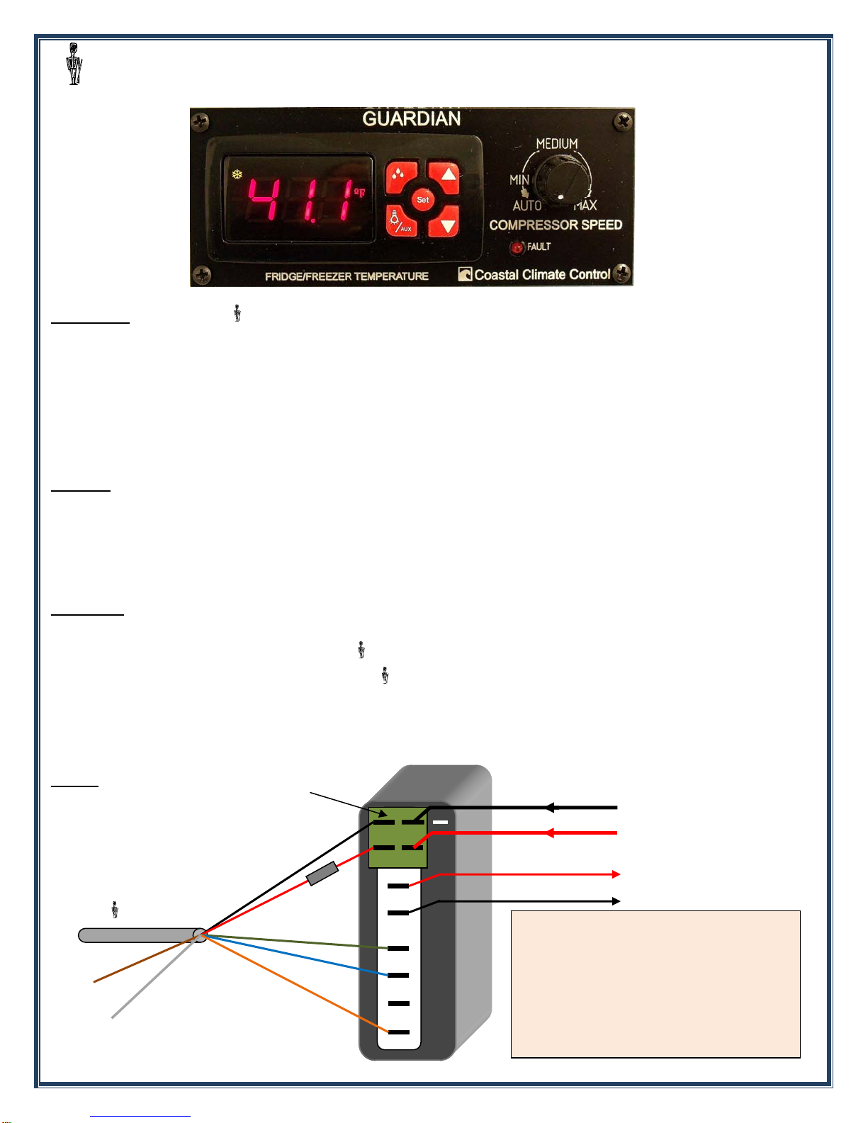
1. Controlsanddisplaysrefrigeratororfreezerboxtemperatureandcompressoroperationalstatus.
2. Providesforautomaticormanualcompressorspeedcontrolformaximumpossiblesystemefficiency.
3. Givesaudibleandvisualindicationoftemperatureanomaliesandsystemmalfunction.
1. TheCoastalMKIIDigitalThermostat/Thermometerispre‐installedandsettoworkasarefrigeratorcontrol
withasetpointof40degreesFahrenheit.Refertoseparateinstructionsheetfordetailsonhowtoadjusttemperature
setpoint,differential,temperaturescale(ForC),andalarmthresholds.
2.Compressorspeediscontrolledbyadjustingtherotaryknob.Wheninthe“AUTO”positionandwithMerlin
SmartSpeedControllerinstalled,thecompressorwillautomaticallyrunatthemostefficientspeed,andchangingthe
knobpositionduringthatcyclewillhavenoeffect.Ifamanualspeedisset,thecompressorwillrunatthatspeedonthe
nextstart‐up.WithoutMerlinSSCinstalled,the“AUTO”settingisnon‐operationalandwillbecomethelowestspeed
setting.Thelowestspeedshouldbesetsothat:(a)theboxmaintainsthedesiredtemperature,and(b)thecompressor
runsforbetween30and45minutesinthehour.Theprinciplebehindcontrollingcompressorspeedbeingthatthe
longerandsloweracompressorcanberun,themoreefficientitwillbeandthelesspoweritwillconsumeoverall.
3.TheDiagnosticLED,labeled“FAULT”,willdisplayaflashingerrorcodeofbetweenoneandfiveflashes
dependentonthenatureofthefault,aslistedbelow.Eachflashingerrorcodecycleisrepeatedevery4seconds.When
afaultisdetected,thecompressorwillstopbutthefanorwaterpump,ifapplicable,willcontinuetorun.Are‐startwill
beattemptedapproximatelyevery60‐90seconds.Thefanorwaterpumpwillstopduringrestartattempts.
OneFlash–Indicateslowvoltage.VoltageatterminalsontheDanfosscontrollerhasdroppedtolessthan10.4v.
Voltagemustthenriseabovethecut‐involtageof11.7vbeforethecompressorwillattemptare‐start.NOTE:If
initialpowerappliedatstart‐upislessthan11.8volts:NocodeflashingonthediagnosticLED,thermostatdigital
displaywillbelit,butthecompressorwillnotstartuntilthevoltagehasrisenabove11.8volts.
TwoFlashes‐IndicatesanoverloadontheFanoutput.Thefanoutputcannotsupportanaverageloadgreater
than0.5amp,orapeakloadgreaterthan1ampfortwoseconds.
ThreeFlashes–Indicatesthatthecompressorcannotstartduetotoohighadifferentialpressureinthe
compressor.Thisisacommonproblemwherepoorvoltage,orbreaksinthepowersupplyorthermostatwiring
causethecontrollertoattemptacompressorre‐starttoosoonafterithasbeenstoppedforsomereason.
FourFlashes–Indicatesthatthecompressorcannotreachminimumspeedof1,850RPM.
FiveFlashes–Indicatesthattheelectronicsheatsinkhasexceeded212degF(100degC).Thiscanbeduetoan
overchargeofrefrigerant,waterinthesystem,orexcessiveambienttemperaturescombinedwithacompressor
operatingunderextremeload.Are‐startwillbeattemptedwhenheatsinkhascooledto170degF(80degC).
PO
Box4535AnnapolisMD21403USA–www.frigoboat.com–[email protected]–301‐352‐5738