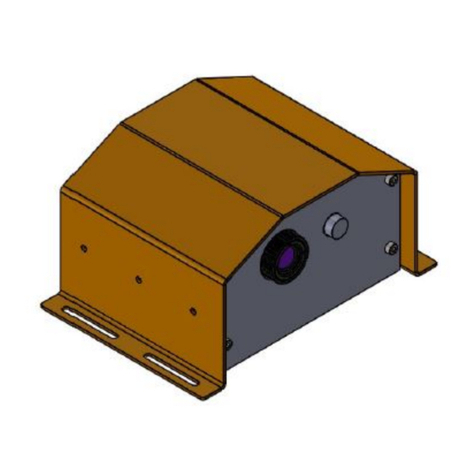
Coatmaster Flex V2 User manual

Maintenance Manual
coatmaster®Flex V2
These operating instructions describe the individual steps of an annual coatmaster® Flex
maintenance based on a photo documentation.

Maintenance manual coatmaster Flex V2.0
Maintenance manual coatmaster Flex V2 EN Page 1of 10 Thomas Baumgartner / 1.2023
© 2019 coatmaster AG
Passing on as well as duplication of this document, utilization and communication of its contents is
not permitted, as far as not expressly granted. Violations will result in damages. All rights reserved in
the event of patent grant or utility model registration (ISO 16016).
Subject to technical changes and printing errors. The data given are approximate values and are not
to be understood as warranted characteristics in the legal sense. The values may vary due to
component tolerances.

Maintenance manual coatmaster Flex V2.0
Maintenance manual coatmaster Flex V2 EN Page 2of 10 Thomas Baumgartner / 1.2023
Index
1 Introduction................................................................................................................................3
2 Material......................................................................................................................................4
2.1 Spare parts (supplied by CM AG) ...................................................................................4
2.2 Tools (not supplied by CM AG)......................................................................................4
3 Maintenance works.....................................................................................................................5
3.1 Cleaning and Care................................................................................................................5
3.2 Safety instructions...............................................................................................................6
3.3 Replacement of the front glass ............................................................................................6
3.4 Replacement of the outlet filter and clean the device inside ...............................................7
3.5 Install a new glass................................................................................................................9
3.6 Replacement of the inlet filter .............................................................................................9
3.7 Send the Service Report to coatmaster..............................................................................10
Table of figures
Fig. 1 spare parts.................................................................................................................................4
Fig. 2 disconnect the battery...............................................................................................................6
Fig. 3 front screws position ................................................................................................................6
Fig. 4 remove the front glass...............................................................................................................6
Fig. 5 cover screws position ................................................................................................................7
Fig. 6 housing opening ........................................................................................................................7
Fig. 7 outlet filter ................................................................................................................................7
Fig. 8 clean inside................................................................................................................................8
Fig. 9 close the housing.......................................................................................................................8
Fig. 10 o-ring position .........................................................................................................................9
Fig. 11 the order of o-ring and the glasses...........................................................................................9
Fig. 12 inlet filter cover opening..........................................................................................................9

Maintenance manual coatmaster Flex V2.0
Maintenance manual coatmaster Flex V2 EN Page 3of 10 Thomas Baumgartner / 1.2023
1Introduction
Read this maintenance instructions completely and carefully before starting the maintenance work.
The maintenance work described in this document may only be carried out by personnel who have
been trained for the maintenance of the coatmaster® Flex by coatmaster AG.
To ensure your own safety, the steps described in chapter 3 must be carried out in a focused and
conscientious manner. Not respecting of the safety instructions can lead to serious injuries and / or
death by electric shock. In addition, only the work described in this document may be carried out.
Any extensions or changes to the hardware or software are forbidden.
If, after you have read this manual and have received personal training from an employee of
coatmaster AG, you are unable to properly perform the work described, contact coatmaster AG.
coatmaster AG
Flugplatzstrasse 5
CH-8404 Winterthur
T +41 52 511 87 77
F +41 52 511 87 49
info@coatmaster.com
www.coatmaster.com
Any liability is refused.
.

Maintenance manual coatmaster Flex V2.0
Maintenance manual coatmaster Flex V2 EN Page 4of 10 Thomas Baumgartner / 1.2023
2Material
2.1 Spare parts (supplied by CM AG)
maintenance Kit (Art Nbr. 100.0013)
1. Inlet filter
2. Outlet filter
3. O-Ring
4. Front glasses spectral blue
5. Front glass white (2mm)
(for no spectral blue Flex)
6. Serial No of the
Maintenance Kit
2.2 Tools (not supplied by CM AG)
7. Torx screwdriver T10
3.
5.
4.
1.
Fig. 1 spare parts
2.

Maintenance manual coatmaster Flex V2.0
Maintenance manual coatmaster Flex V2 EN Page 5of 10 Thomas Baumgartner / 1.2023
3Maintenance works
For any repair or service of the device, excluding maintenance level 1, please send
the coatmaster® Flex back to the manufacturer coatmaster AG.
Maintenance level 1: coatmaster® Flex needs to be at least weekly inspected,
against inlet filter cleanliness, front glass transparency and cleanliness. A set of
inlet filters and a front glass are provided together with your coatmaster® Flex.
For higher quantities, Inlet filters and front glasses can be ordered online through
flex.coatmaster.com.
In case of any other manipulation or opening of the device, the warranty claim will be immediately
terminated.
The following table gives you an overview of the items that needs to be regularly maintained on your
coatmaster® Flex.
Item
Description Level
Maintenance Level
Done by
Inlet filter
Regular maintenance
User
Outlet filter
Extraordinary maintenance
coatmaster AG / Distributor
Front Glass
Extraordinary maintenance
coatmaster AG / Distributor
Internal
cleaning
Extraordinary maintenance
coatmaster AG / Distributor
SW-Update
Extraordinary maintenance
coatmaster AG / Distributor
Maintenance Level:
Level 1: can be done by the user of the coatmaster® Flex
Level 2: must only be done by a coatmaster AG Technician or a coatmaster Distributor
It’s prohibited to do a Level 2 Maintenance by user or any other technician besides coatmaster AG.
If so, the warranty claim will be immediately terminated.
3.1 Cleaning and Care

Maintenance manual coatmaster Flex V2.0
Maintenance manual coatmaster Flex V2 EN Page 6of 10 Thomas Baumgartner / 1.2023
3.2 Safety instructions
Before beginning the maintenance on the coatmaster, the following steps
must be carried out according to the safety rules of electrical engineering:
3.2.1 Disconnect from the power supply!
Switch off the coatmaster, wait until the screen and the fan
turns off. Remove the battery from the coatmaster® Flex.
3.3 Replacement of the front glass
Front glass can only be replaced with spare parts supplied by
coatmaster AG. Using other spare parts can lead to a damage to
the device.
3.3.1 Remove the front metal ring
Unscrew the front 4 x M3 screws with a torx T10 screwdriver. The
front metal ring can be easily removed.
3.3.2 Remove the front glass
Turning the device upside down, the front glass(es) should leave
the housing. If this is not the case, rotate the glass(es) right and left,
until you can easily remove it with the hands.
The next step is the replacement of the outlet filter and
clean the device inside.
Fig. 2 disconnect the battery
Fig. 3 front screws position
Fig. 4 remove the front glass

Maintenance manual coatmaster Flex V2.0
Maintenance manual coatmaster Flex V2 EN Page 7of 10 Thomas Baumgartner / 1.2023
3.4 Replacement of the outlet filter and
clean the device inside
3.4.1 Uncover the coatmaster® Flex housing
Unscrew the 4 screws with a torx T10 screwdriver as
showen in the picture aside. Be careful, once the cover is
unscrewed, it can fall and break.
Gently open partially the cover.
Replace the black outlet filter.
Fig. 5 cover screws position
Fig. 6 housing opening
Fig. 7 outlet filter

Maintenance manual coatmaster Flex V2.0
Maintenance manual coatmaster Flex V2 EN Page 8of 10 Thomas Baumgartner / 1.2023
Clean the coatmaster Flex inside with a paint brush.
Check that all the wires are connected and don’t bind in the screw’s holes.
3.4.2 Visual inspection
Before the housing is screwed on again, make sure that there are no loose small parts or tools in the
device, otherwise there is a possibility of damaging the coatmaster® Flex.
3.4.3 Assemble the coatmaster® Flex housing
First assembly the front cover, then the rear cover around the display. To snap the rear cover in, hold
the front cover in position and press the rear cover on the top against the front cover.
Screw on the screws with a torx T10 screwdriver.
Fig. 8 clean inside
Fig. 9 close the housing
until «clack»
1
2

Maintenance manual coatmaster Flex V2.0
Maintenance manual coatmaster Flex V2 EN Page 9of 10 Thomas Baumgartner / 1.2023
3.5 Install a new glass
Position the new glasses on the lamp. Check that the black O-
ring is in the right position as in the picture and that the insert
first the thin white glass and at last the blue glass. Check the
white glass is not touching the lamp.
Assemble the front metal ring and tighten the 4 x M3 screws with a torx T10 screwdriver.
Check that the front glass is well fixed.
3.6 Replacement of the inlet filter
The inlet filter must be inspected, at least weekly, by the user of
the coatmaster® Flex to avoid a malfunction of the device. If it is
dirty, change the filter; otherwise, change the filter every
month or after 80 hours of use, whichever is earlier.
Open the bottom cover and replace the inlet filter. The filter
must be positioned correctly, with the hard part upside (by
touching the filter it is possible to define the hard and the soft
side).
Close the bottom cover.
Fig. 10 o-ring position
Fig. 12 inlet filter cover opening
1
2
3
Fig. 11 the order of o-ring and the glasses

Maintenance manual coatmaster Flex V2.0
Maintenance manual coatmaster Flex V2 EN Page 10 of 10 Thomas Baumgartner / 1.2023
3.7 Send the Service Report to coatmaster
Send the completed “service report distributors” to coatmaster AG maintenance@coatmaster.com.
Documents to send:
-completed report “service report distributors”
-completed CoC “Certificate of Calibrationen Flex”
After receiving the documents, coatmaster will reset the maintenance-message on the Flex within
the next two working days.
coatmaster AG
Flugplatzstrasse 5
CH-8404 Winterthur
T +41 52 511 87 77
F +41 52 511 87 49
info@coatmaster.com
www.coatmaster.com
Table of contents
Other Coatmaster Measuring Instrument manuals