manuals.online logo
Brands
  1. Home
  2. •
  3. Brands
  4. •
  5. COBHAM
  6. •
  7. Antenna
  8. •
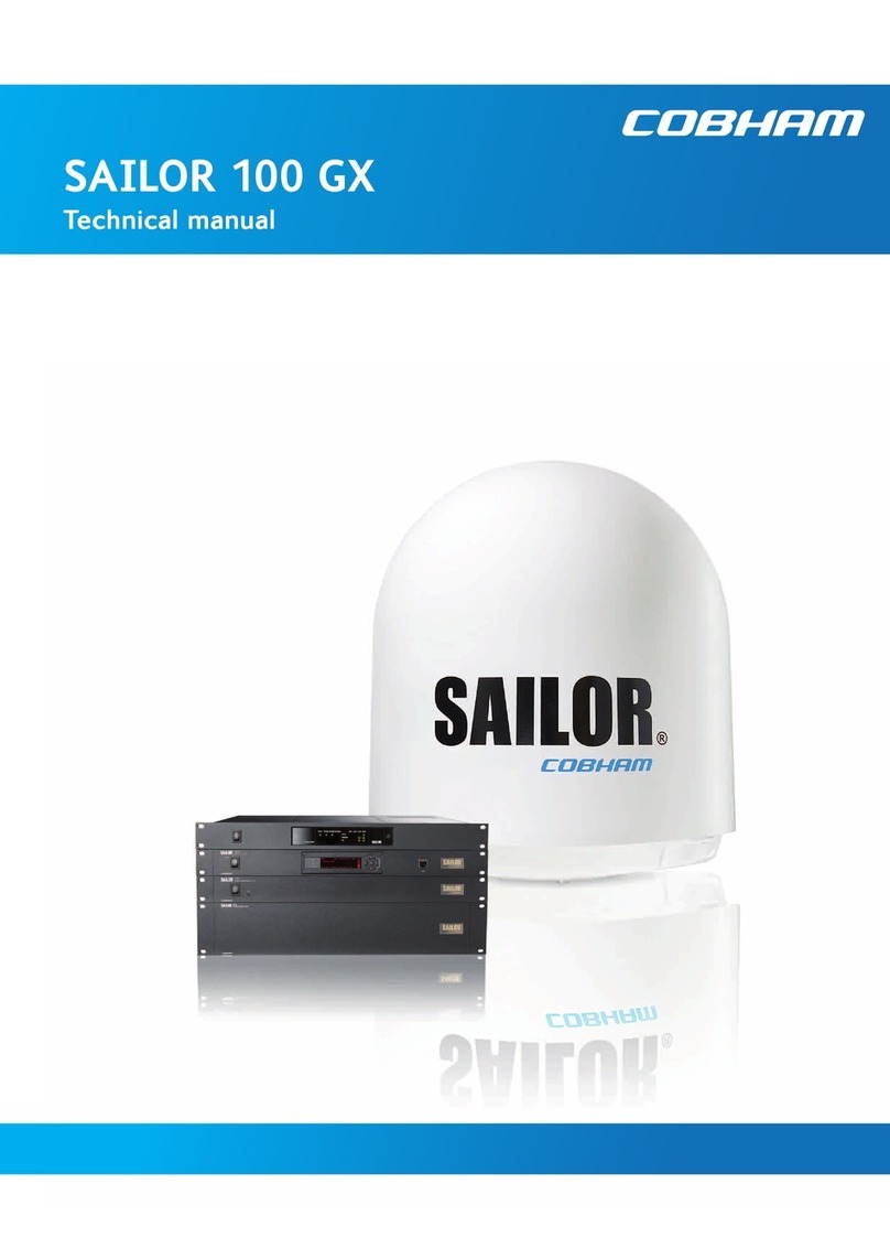
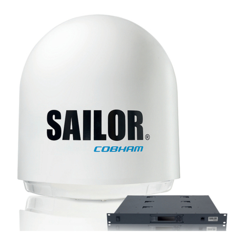
  9. COBHAM SAILOR 100 TV Use and care manual

COBHAM SAILOR 100 TV Use and care manual

Field
Replacement
Procedure
Following legal entities are trading as / doing
business as Cobham SATCOM
Thrane and Thrane A/S, Kgs. Lyngby, Denmark
Sea Tel Inc., Concord USA
TracStar Systems Inc., Orlando, USA
Omnipless Manufacturing (Pty) Limited, Cape Town, RSA
www.cobham.com/satcom
SAILOR 100 TV & SAILOR 800, 900A & 900B VSAT – Polarization Motor Module
(PMM) Procedure
Brief Summary:
Troubleshooting document for inspecting and replacing the polarization motor module (S-62-131002)
on the SAILOR 100 (7309A) TV antenna and SAILOR 800 (7008A), 900A (7009A) and 900B (7009B)
VSAT antennas.
Checklist:
Status LEDs
Events List / Error Log. Identify Defective Part
Replace Part
Verify Initialization and Run POST Test
Theory of Operation:
The Polarization Motor Module (PMM) controls the polarity angle of the antenna by aligning the
polarization unit on the back of this dish at the correct angle to match the linear satellite signal from
the vessels GPS location for optimum signal strength. On the SAILOR 800 and 900 VSAT antennas this
will also ensure the transmit signal is correctly aligned to prevent interference with the services on the
opposite polarity.
The PMM drives a stepper motor on the back of the dish to rotate the polarization unit of the VSAT
antennas or the LNB of the TV antenna, based on commands from the Pedestal Control Module (PCM)
to optimise the polarity look angle of the system.
The polarity angle is calculated using the GPS position of the vessel and the look angle to the desired
satellite. Upon initialization the position of the VSAT polarization unit is calibrated using a reference
point (magnet) on the polarization unit and a Hall Effect sensor installed on the Zero Reference
Module (ZRM) on the polarization axis. Whereas the TV antenna drives the polarity stepper motor
from end-stop to end-stop to verify the full range of motion and calibrate its position.
Once calibrated the VSAT antennas use an encoder installed on the polarization unit to count the
increments/decrements of the polarization drive and provides this feedback to the PCM as a reference,
where as the TV antenna counts the steps of the polarization motor to calculate the angle of the LNB.
Cobham SATCOM
Global Customer Service dept.
Document no.: 97-138940-D
Revision: D
Date: April 2013
Page 2 of 10
www.cobham.com
/satcom
Spare Part Instruction – SAILOR 100, 800 & 900A/B PMM
Document No.: 97-138940-D
Revision: D
The PMM has two LEDs for status and troubleshooting, should there be a fault with the antenna the
system will go into safe mode. The pedestal voltage will drop from 48VDC to 20VDC, causing the DDM
service LED’s to illuminate red to prevent the antenna from being able to drive. If this was caused by
a defective PMM its service LED would also be illuminated red. All power LED’s should remain green
providing they are receiving voltage.
Troubleshooting - Diagnostic LEDs on the ACU:
The ACU has 3 LEDs: Power, Logon and Fail/Pass.
Verify the status of the unit by referencing the LEDs. If any of the LEDs are not steady green or
flashing green then further diagnostics will need to be undertaken, referencing the below table:
If the Fail/Pass LED is illuminated any colour other than steady green then it means there is an issue
with the system. Log into the ACU using your web browser and refer to the systems event log as
detailed in the following sections of this document.
Page 3 of 10
www.cobham.com
/satcom
Spare Part Instruction – SAILOR 100, 800 & 900A/B PMM
Document No.: 97-138940-D
Revision: D
Log into the Antenna Control Unit (ACU):
1. Connect a straight through Ethernet cable from the LAN port of your laptop to the “LAN 3” port
of the ACU.
2. Open the “Network and Sharing Center” on your laptop and select “Change Adaptor Settings”.
3. Right-Click the LAN adaptor for your laptop and select the “Properties” tab.
Continued…
Page 4 of 10
www.cobham.com
/satcom
Spare Part Instruction – SAILOR 100, 800 & 900A/B PMM
Document No.: 97-138940-D
Revision: D
4. Double click the “Internet Protocol Version 4 (TCP/IPv4)” Option.
5. The Select the “Use the following IP address” button and enter in an IP address of “192.168.0.2”
and a Subnet Mask of “255.255.255.0”.
6. Now click the OK button on both the “IP Protocol Version 4 (TCP/IP)” window and the “Local
Area Connection Properties” window.
7. Open your web browser and enter the IP address “192.168.0.1”, then press the enter button.
Continued…
Page 5 of 10
www.cobham.com
/satcom
Spare Part Instruction – SAILOR 100, 800 & 900A/B PMM
Document No.: 97-138940-D
Revision: D
8. You’ll now have access to the systems “DASHBOARD”.
9. The following procedure will tell you how to access the events list and diagnose any errors or
warnings with the system.
Page 6 of 10
www.cobham.com
/satcom
Spare Part Instruction – SAILOR 100, 800 & 900A/B PMM
Document No.: 97-138940-D
Revision: D
Troubleshooting – Event List:
When an event is registered the web interface shows an event icon “ ” in the icon bar as long as
the event is active, the ACU display also shows active events.
To view the event list with active events click the event icon from the icon bar ( ) at the top of the
web interface or select “HELPDESK” and then “Event list” from the navigation pane on the left of the
user interface.
The Events List page then shows a list of active events and notifications including:
The time and date of the first occurrence (Time UTC)
The event code (ID)
The severity of the event message (Severity)
A description describing the event (Text)
For a more comprehensive diagnosis of the event displayed reference the error and event codes
document, document number: 97-139344-A. Once diagnosed replace the defective component and
run the Power On Self Test (POST) and verify the operation of the system.
*Note: Active events are cleared from the event list when the error is cleared. They are then moved
to the notifications section and are displayed there with the severity, after 24 hours the notifications
are then cleared or after the system is restarted.
Page 7 of 10
www.cobham.com
/satcom
Spare Part Instruction – SAILOR 100, 800 & 900A/B PMM
Document No.: 97-138940-D
Revision: D
Replacing the Polarization Motor Module:
Tools needed:
•Torx TX20 Screwdriver
•4mm Allen Key (provided in the radome hatch, part number: S-47-206968-004)
•Small Flat-Head Screw Driver
1. Open the service hatch by releasing the two latches
using a Torx TX20 screwdriver (if applicable).
2. Rotate the antenna pedestal so that the arm with the
GPS module faces the service hatch.
3. Switch off the power to the antenna using the service
switch, located on the rear of the pedestal.
4. Locate the PMM on the rear of the dish.
5. Rotate the antenna dish to 90 degrees of elevation
(facing upwards).
6. Press in and turn the elevation locking pin to the
locked position (if applicable).
7. Rotate the polarisation unit so that the PMM can be
reached.
8. Disconnect the 6 connectors from the PMM, using a
small flat-head screwdriver for the D-sub connector.
*Note: The SAILOR 100 TV only uses the “M” (motor
connector) and D-sub connector.
9. Remove the four 4mm Allen bolts securing the PMM
to the pedestal using the Allen key provided in the
service hatch of the antenna. Retain the hardware for
future use.
10. Remove the defective PMM.
Page 8 of 10
www.cobham.com
/satcom
Spare Part Instruction – SAILOR 100, 800 & 900A/B PMM
Document No.: 97-138940-D
Revision: D
11. To install a replacement PMM follow the instructions
above in reverse order, while following the below
guidelines:
12. Connect the 6-pin connector with the coloured wires
(polarization encoder) to the plug marked “ORE” on the
PMM.
13. Connect the 6-pin connector with 4 white wires to
the plug marked “ZRM” on the PMM.
14. Connect the 6-pin connector with 6 white wires to
the plug marked “OMT” on the PMM.
*Note: These wires don’t apply to the SAILOR 100 TV
antenna.
15. Once the replacement PMM has been installed verify
that the antenna passes the Power On Start up Test
(POST) as per the following procedure.
Page 9 of 10
www.cobham.com
/satcom
Spare Part Instruction – SAILOR 100, 800 & 900A/B PMM
Document No.: 97-138940-D
Revision: D
Troubleshooting - Verify the Initialization of the Pedestal:
After replacing the defective component re-initialize the pedestal and verify its operation. First switch
off the power to the antenna using the service switch, located on the rear of the pedestal:
Then restart the pedestal by pressing and holding the and arrows on the ACU together:
Now view the pedestal through the service hatch and switch on the service switch located on the rear
of the pedestal. Now verify the Initialization process is as follows:
1. The elevation axis will drive from end-stop to end-stop and then to its zero reference point, with
the reflector at 45 degrees.
2. The cross-elevation then drives from end-stop to end-stop and then to its zero reference point,
level with the horizon.
3. Then the azimuth axis drives one direction and then back on itself before settling at its zero
reference point, with the antenna facing away from the service hatch.
4. A VSAT antenna will then drive the polarization unit from end-stop to end-stop and then back to
its zero reference point, at which point the polarization motor module will be at the highest point,
with the LNB coax cables pointing left. (The TV antenna wont drive its polarization motor until
after the POST).
*Note: Any errors during the Power On Self Test (POST) will make the system go to safe mode,
dropping the ADU power from 48VDC to 20VDC and making the DC-Motor Drive Modules (DDM)
status LEDs illuminate red.
A minor issue with the POST may enable the system to operate, with the Antenna Control Unit (ACU)
displaying a warning. If the Pass/Fail LED is illuminated on the ACU, refer to the error log for further
information.
5. The system will then go into ‘ready mode’, expecting to get the satellite tracking parameters from
the satellite modem or systems dashboard.
6. Once the tracking information has been received the system will begin to target the satellite at
which point the TV antenna will drive its polarization motor clockwise into its end-stop to calibrate
itself, before driving to the correct look angle for the desired satellite.
7. The Above Deck Unit (ADU) then goes from pointing the antenna to then acquiring the signal, and
finally into tracking mode.
8. Verify the system completed the initialization process correctly and that no errors were flagged by
the POST.
Page 10 of 10
www.cobham.com
/satcom
Spare Part Instruction – SAILOR 100, 800 & 900A/B PMM
Document No.: 97-138940-D
Revision: D
Troubleshooting - Self Test:
You can run a self test on the ACU and ADU of the antenna system.
1. From the “HELPDESK” page, click the “Self test” option.
2. The system will now run the Self test.
3. Ensure the test is completed with no errors.
4. If any errors are displayed refer to the “ACU Error Messages” section of this document for further
information.

This manual suits for next models

3

Other COBHAM Antenna manuals

COBHAM 3.8m Offset Antenna User manual

COBHAM

COBHAM 3.8m Offset Antenna User manual

COBHAM Sailor 900 VSAT User manual

COBHAM

COBHAM Sailor 900 VSAT User manual

COBHAM SAILOR 900 Ka User manual

COBHAM

COBHAM SAILOR 900 Ka User manual

COBHAM Sea Tel 09 Series Manual

COBHAM

COBHAM Sea Tel 09 Series Manual

COBHAM Sea Tel 6011-4 User manual

COBHAM

COBHAM Sea Tel 6011-4 User manual

COBHAM SAILOR XTR Ku User manual

COBHAM

COBHAM SAILOR XTR Ku User manual

COBHAM EXPLORER 7100GX User manual

COBHAM

COBHAM EXPLORER 7100GX User manual

COBHAM Sea Tel User manual

COBHAM

COBHAM Sea Tel User manual

COBHAM Explorer 710 User manual

COBHAM

COBHAM Explorer 710 User manual

COBHAM EXPLORER 8100 GX User manual

COBHAM

COBHAM EXPLORER 8100 GX User manual

COBHAM SAILOR 900 User manual

COBHAM

COBHAM SAILOR 900 User manual

COBHAM Sea Tel User manual

COBHAM

COBHAM Sea Tel User manual

COBHAM EXPLORER 5075GX User manual

COBHAM

COBHAM EXPLORER 5075GX User manual

COBHAM SAILOR 800 VSAT Use and care manual

COBHAM

COBHAM SAILOR 800 VSAT Use and care manual

COBHAM Explorer 325 User manual

COBHAM

COBHAM Explorer 325 User manual

COBHAM SAILOR 1000 XTR Ka 4.5W ADU User manual

COBHAM

COBHAM SAILOR 1000 XTR Ka 4.5W ADU User manual

COBHAM Sailor 500 FleetBroadband User manual

COBHAM

COBHAM Sailor 500 FleetBroadband User manual

COBHAM Sea Tel 9711-56 IMA C Band User manual

COBHAM

COBHAM Sea Tel 9711-56 IMA C Band User manual

COBHAM Explorer 3075 User manual

COBHAM

COBHAM Explorer 3075 User manual

COBHAM SAILOR 600 VSAT Ka User manual

COBHAM

COBHAM SAILOR 600 VSAT Ka User manual

COBHAM Sailor 150 FleetBroadband User manual

COBHAM

COBHAM Sailor 150 FleetBroadband User manual

COBHAM EXPLORER 6075LX Guide

COBHAM

COBHAM EXPLORER 6075LX Guide

COBHAM Sea Tel 4010W-33 User manual

COBHAM

COBHAM Sea Tel 4010W-33 User manual

COBHAM Saailor Fleet One User manual

COBHAM

COBHAM Saailor Fleet One User manual
Popular Antenna manuals by other brands

Maxview MXR0010 user guide

Maxview

Maxview MXR0010 user guide

Cerio ANT-0608WN installation guide

Cerio

Cerio ANT-0608WN installation guide

Cisco 4G-LTE-ANTM-O-3 installation guide

Cisco

Cisco 4G-LTE-ANTM-O-3 installation guide

Raymarine RD418HD user guide

Raymarine

Raymarine RD418HD user guide

TRENDnet TEW-AI77OB - Duo 7dBi Indoor Omni Directional... Quick installation guide

TRENDnet

TRENDnet TEW-AI77OB - Duo 7dBi Indoor Omni Directional... Quick installation guide

Parsec Technologies NEWFOUNDLAND L installation instructions

Parsec Technologies

Parsec Technologies NEWFOUNDLAND L installation instructions

TDK HBA-2030 datasheet

TDK

TDK HBA-2030 datasheet

Microwave Radio Communications Ellipse 2000 installation guide

Microwave Radio Communications

Microwave Radio Communications Ellipse 2000 installation guide

Encore ENAT-OD7 datasheet

Encore

Encore ENAT-OD7 datasheet

TE Connectivity WMM8G-7-38 Installation Guide and Safety Information

TE Connectivity

TE Connectivity WMM8G-7-38 Installation Guide and Safety Information

Siklu EtherHaul 8000 Series Installation, operation and maintenance manual

Siklu

Siklu EtherHaul 8000 Series Installation, operation and maintenance manual

A.H. Systems AK-4G Operation manual

A.H. Systems

A.H. Systems AK-4G Operation manual

Teleco VoyagerG3 65 Installation guide and user's manual

Teleco

Teleco VoyagerG3 65 Installation guide and user's manual

STI-CO CPMT-SB-VHF installation instructions

STI-CO

STI-CO CPMT-SB-VHF installation instructions

Winegard SENSAR III Installation & operation manual

Winegard

Winegard SENSAR III Installation & operation manual

Sirius XM RAdio XM Indoor installation guide

Sirius XM RAdio

Sirius XM RAdio XM Indoor installation guide

Ubiquiti airMAX Titanium Sector quick start guide

Ubiquiti

Ubiquiti airMAX Titanium Sector quick start guide

KING One Pro KOP4800 owner's manual

KING

KING One Pro KOP4800 owner's manual

manuals.online logo
manuals.online logoBrands
  • About & Mission
  • Contact us
  • Privacy Policy
  • Terms and Conditions

Copyright 2025 Manuals.Online. All Rights Reserved.