Adapter for Database Updates
(R10G Only)
Accessories Order Info and
Trademark Acknowledgement
Customer Assistance
Ordering From U.S.A.
Call 773-889-3087 for pricing or visit www.cobra.com.
For Credit Card Orders
Call 773-889-3087 [Press one from the main menu] 8:00 a.m. to 6:00 p.m. Central Time,
Monday through Friday.
Make Check or Money Order Payable To
Cobra Electronics, Attn: Accessories Dept.,
6500 West Cortland Street, Chicago, IL 60707 U.S.A.
To Order Online
Please visit our website: www.cobra.com
Item # Description
CLP-2B Dual Port Power Adapter
RDA GPSL55 GPS Locator Upgrade (for Model XRS R8 Only)
RDA LIBP LiON Replace ent Battery Pack
RDA RDU Replace ent RDU
Introduction
Nothing Come Clo e to a Cobra®A3
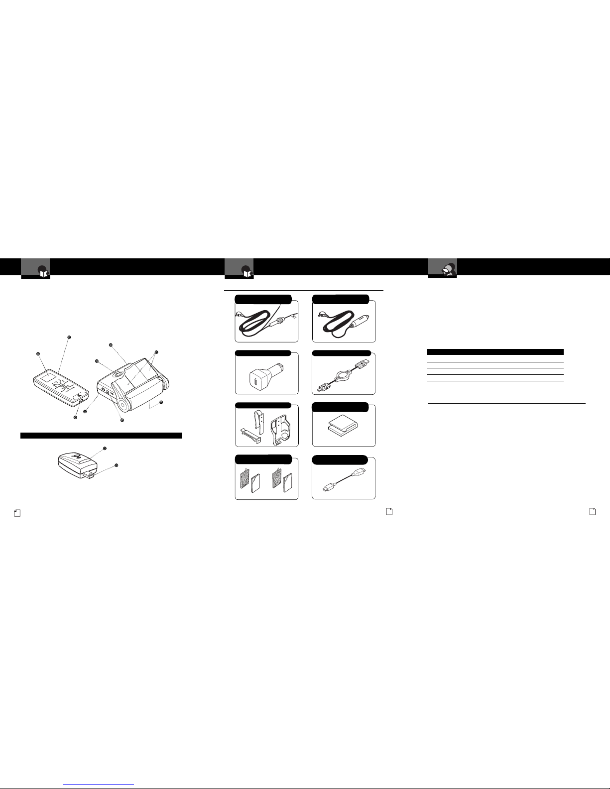
Accessories In This Package
Accessories In This Package •
RDU USB to Mini-USB Retractable Cable
RDU Holster and Vent/Visor Clips
RDU 12V to 5V USB Power Adapter
Controls, Indicators
and Connections
Introduction
A2 English
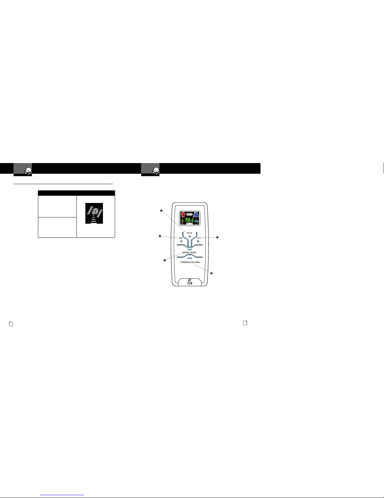
Intelli ink™Remote Display Unit (RDU)
Full-Color
Extreme Bright
DataGrafix™
Display
Plug-in Global Positioning
System ocator
USB Power Connector
for Recharging Battery 12V Power Connector
USB Connector
Power
Button
Two-Piece,
Self-Adhesive
Fasteners
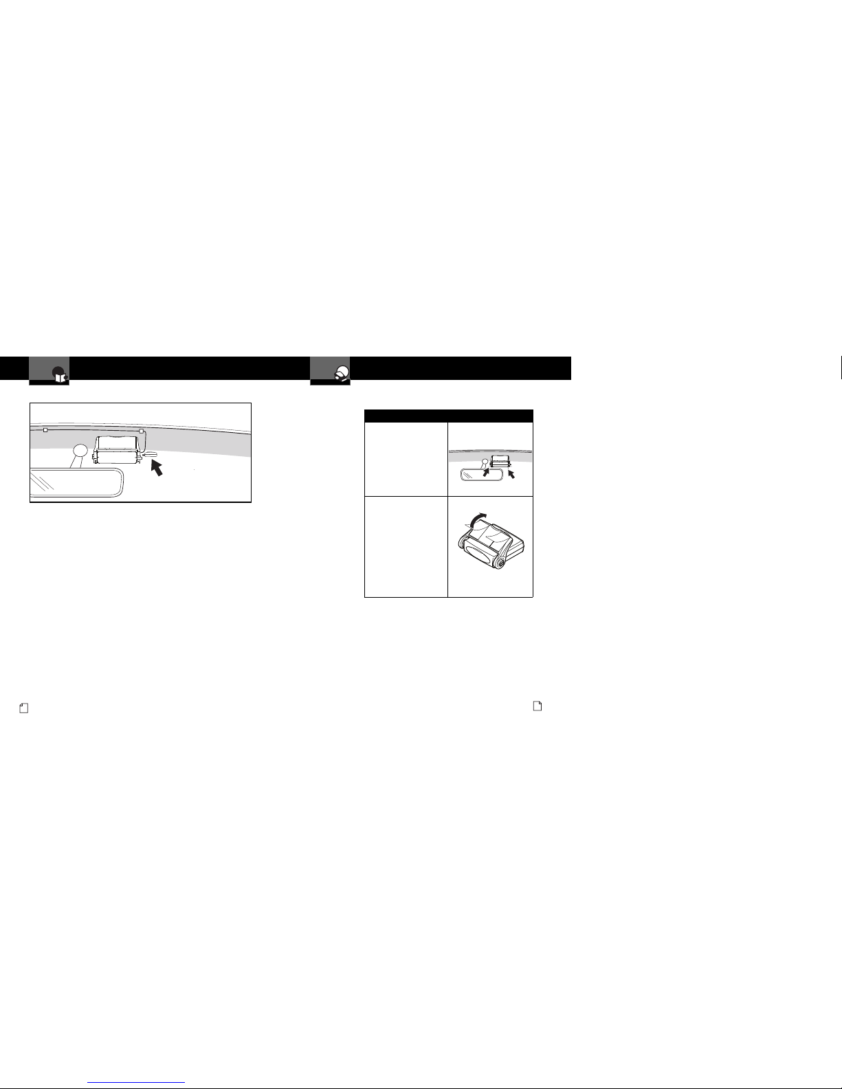
Main Detector Unit (MDU)
Speaker
GPS ocator for Model XRS R10G (Optional for Model XRS R8)
The XRS R8 provides detection capabilities for radar, laser and strobe signals.
The XRS R10 has all the features of the XRS R8 plus a PS locator module
which provides alerts when approaching photo-enforced intersections, roads
with fixed red light/speed cameras and caution areas (such as a high-accident
intersection). The XRS R10 can store up to 1,000 additional user-programmable
Location Alerts.
USB Port for
Connection of
GPS ocator
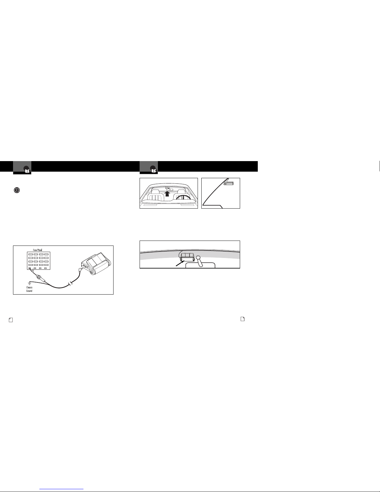
MDU 12V Power Cord with In-line
Fuse for Hardwired Installation
MDU 12V Power Cord with In-line
Fuse and Cigarette ighter Plug
Hook and oop Strips for Alternate
Holster Mounting.
MDU Power Cord Clips and Pre-cut
Adhesive Tapes
Nothing Come Clo e to a Cobra®45
Trademark Acknowledgement •
Cobra®, DigiView®, EasySet®, Extra Sensory Detection®, IntelliMute®, IntelliMute®Pro,
IntelliShield®, LaserEye®, Nothing Comes Close to a Cobra®, Safety Alert®Traffic
Warning System, Strobe Alert®, V -2 Alert®, Xtreme Range Superheterodyne®and
the snake design are registered trademarks of Cobra Electronics Corporation, USA.
Cobra Electronics Corporation™, 14 Band™, 15 Band™, Extreme Bright Data rafix™,
IntelliLink™, IntelliScope™, IntelliView™, Revolution™ Series, SmartPower™,
Spectre Alert™, Super-Xtreme Range Superheterodyne™, S-XRS™, UltraBright™,
and Voice Alert™ are trademarks of Cobra Electronics Corporation, USA.
Opticom™ is a trademark of 3M Corporation. Instaclear®for Ford is a registered
trademark of Ford Motor Company, Inc. Electriclear®for M is a registered trademark
of eneral Motors Corporation. 20-20™ and Ultra-Lyte™ are trademarks of Laser
Technology, Inc. ProLaser™ and ProLaser III™ are trademarks of Kustom Signals,
Inc. Bee III™ and Pop™ are a trademarks of MPH Industries. Stalker™ LIDAR is a
trademark of Applied Concepts, Inc. Spectre I™ and Spectre IV+™ are trademarks of
Stealth Micro Systems Pty. Ltd. SpeedLaser™ is a trademark of Laser Atlanta, LLC.
Interceptor V -2™ is a trademark of TechniSonic Industries LTD. Tomar®is a
registered trademark of TOMAR Electronics, Inc.