Code Blue PHXS01 Manual

IP1500 and IP2500 Series
Administrator Guide
WARNING
ONLY QUALIFIED PERSONNEL SHOULD INSTALL THESE UNITS. THE INSTALLATION
SHOULD CONFORM TO ALL LOCAL CODES. IN SOME COUNTRIES, A CERTIFIED
ELECTRICIAN MAY BE REQUIRED.
NOTICE TO USERS
Copyright © Code Blue Corporation. All rights reserved. This guide or software
described herein, in whole or part, shall not be reproduced, translated or reduced to any
machine-readable form without prior written approval from Code Blue Corporation.
CODE BLUE CORPORATION PROVIDES NO WARRANTY WITH REGARD TO THIS
GUIDE, THE SOFTWARE OR OTHER INFORMATION CONTAINED HEREIN AND HEREBY
EXPRESSLY DISCLAIMS ANY IMPLIED WARRANTIES OF MERCHANTABILITY OR
FITNESS FOR ANY PARTICULAR PURPOSE WITH REGARD TO THIS GUIDE, THE
SOFTWARE OR SUCH OTHER INFORMATION. IN NO EVENT SHALL CODE BLUE
CORPORATION BE LIABLE FOR ANY INCIDENTAL, CONSEQUENTIAL, OR SPECIAL
DAMAGES, WHETHER BASED ON TORT, CONTRACT, OR OTHERWISE, ARISING OUT
OF OR IN CONNECTIONS WITH THIS GUIDE, THE SOFTWARE OR OTHER
INFORMATION CONTAINED HEREIN OR THE USE THEREOF.
Code Blue Corporation reserves the right to make any modifications to this guide or the
information contained herein at any time without notice. The software described herein
may also be governed by the terms of a separate user license agreement.
Code Blue® is a registered trademark of Code Blue Corporation. The names of actual
companies and products mentioned herein may be the trademarks of their respective
owners.
page 2 of 75
GU-137-P
Code Blue • 259 Hedcor Street • Holland, MI 49423 USA • 800.205.7186 • www.codeblue.com

Table of Contents
Section
Section Title
Page #
2
Introduction
4
3
Safety Information
5
Special Warning
6
Shielded Patch Cable
7
4
Installation Instructions
8
IP1500
9
IP1501
10
IP2500
12
IP2501
13
5
Wiring Diagrams
15
Printed Circuit Board Layout
16
IP1500/1501
17
IP2500/2501
18
6
Provisioning the Phone
19
Determine the IP Address
19
Logging into the System
20
Logging out of the System
21
Network Configuration
22
VLAN Configuration
23
Configuring VoIP Settings
24
Configuring VoIP Accounts
24
Configuring SIP Account
25
Configuring an IAX Account
26
Configuring Media Settings
27
Configuring Advanced Settings
28
Configuring the System Settings
29
System Administration Settings
30
Date & Time Configuration
31
IP1500 and IP2500 Series
Administrator Guide
page 3 of 75
GU-137-P
Code Blue • 259 Hedcor Street • Holland, MI 49423 USA • 800.205.7186 • www.codeblue.com

Table of Contents (continued)
IP1500 and IP2500 Series
Administrator Guide
page 4 of 75
GU-137-P
Code Blue • 259 Hedcor Street • Holland, MI 49423 USA • 800.205.7186 • www.codeblue.com
Section
Section Title
Page #
7
Upgrading Firmware
32
8
Configuring System Options & Scripts
33
Batch Configuration
33
Entering Phone Numbers
34
Recordings Administration
35
Hardware Settings
36
General Settings
37
Action Script Configuration
38
Scripting Basic Call
38
Action Script Parameters
41
Sample Application using dual Accounts on the IP1500/2500 Phone
43
Auxiliary Output Expanded Functionality & Use Case
44
Configuring Diagnostics
45
9
CLI (Command Line Interface)
46
10
In-Call Commands
47
12
Factory Reset
48
13
Compatibility
50
14
Configuring for Cisco Unified Communications Manager 9
51
15
UCM Configuration
53
16
Configuring End Users for Secondary Accounts
54
17
Avaya IP Office Integration Guide
56
18
Power Requirements
63
19
Using the IP1500 and IP2500 Series Speakerphones
67
20
Button and Activation Specifications
68
21
Speaker Specifications
69
22
Remote Mount Beacon/Strobe Installation
70
23
Maintenance Schedule
71
24
Warranty
73
25
Download Information
74
26
Legal & Regulatory Information
75

2 Introduction
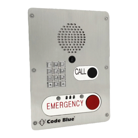
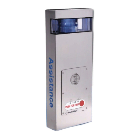
IP2501-s Flush Mount
IP2500-s Surface Mount
IP2501-d Flush Mount
IP2500-d Surface Mount
IP1501 Flush Mount
IP1500 Surface Mount
Thank you for choosing the Code Blue IP1500 and IP2500 Series full duplex VoIP
speakerphone(s), intercom, and paging device(s) for indoor and outdoor applications. These
speakerphones are built to meet the latest regulations, withstand the harshest elements and be
proactive solutions for when you need them most. This guide provides basic and advanced
configuration information for obtaining the best performance with the IP1500 and IP2500
Series speakerphone(s).
IP1500 and IP2500 Series
Administrator Guide
page 5 of 75
GU-137-P
Code Blue • 259 Hedcor Street • Holland, MI 49423 USA • 800.205.7186 • www.codeblue.com

IP1500 and IP2500 Series
Administrator Guide
Indicates a hazardous situation which, if not avoided, will result in
death or serious injury.
Indicates a hazardous situation which, if not avoided, could result in
death or serious injury.
CAUTION
Indicates a hazardous situation which, if not avoided, could result in
minor or moderate injury.
NOTICE
Indicates a situation which, if not avoided, could result in damage to
property.
IMPORTANT
Indicates significant information that is essential for proper product
functionality.
NOTE
Indicates useful information that helps get the most out of a
product.
3 Safety Information
HAZARD LEVELS LEGEND
WARNING
DANGER
Safety Instructions
Code Blue products shall be installed by trained professionals. The installation should
conform to all local codes. In some countries, a certified electrician may be required.
When transporting a Code Blue product, use the original packaging or equivalent to
prevent damage to the product.
Code Blue products shall be used in compliance with local laws and regulations.
Store the Code Blue product in a dry and ventilated environment.
Do not install the product on unstable brackets, surfaces or walls.
Use only applicable tools when installing Code Blue products.
Do not use chemicals, caustic agents, steel wool or aerosol cleaners other than those
tested and recommended by Code Blue.
Use only accessories that comply with technical specifications of the product. These
can be provided by Code Blue or a third party.
Use only spare/replacement parts provided by or recommended by Code Blue.
Transportation
When transporting a Code Blue product, use the original packaging or equivalent to
prevent damage to the product.
WARNING
NOTICE
NOTICE
page 6 of 75
GU-137-P
Code Blue • 259 Hedcor Street • Holland, MI 49423 USA • 800.205.7186 • www.codeblue.com

Special Warning: High Voltage – Range 37 - 57V DC <12.96 watts (27mA)
Grounding
There must be an uninterruptible safety earth ground attached to the grounding lanyard provided.
Whenever it is likely that the protection has been impaired, disconnect the Ethernet cable until the
ground has been restored. This is a non-emergency, non-monitored product line.
Ground terminations points have been marked in accordance with UL 2017 standards. Approved icons
have been applied to indication the grounding location.
Ground Wire Connection
Locate the 18g green ground wire, which is terminated with a ring lug that has been secured to a
faceplate stud. The loose end of the green ground wire must be secured to an earth ground nearby.
If the enclosure has marked grounding location, and a green grounding screw is available, please use it
whenever local codes dictate earth ground is required. Ground termination locations can be labelled
using the following graphic symbol:
Ground Images sample:
There are no user-serviceable parts inside these products. Any servicing, adjustment, maintenance or
repair must be performed only by service-trained personnel. These products do not have a power
switch; they are powered on when the Ethernet PoE cable is plugged in.
ELECTRICAL SAFETY WARNINGS
This device is suitable for use in non-hazardous locations only.
WARNING: Explosion Hazard – Do not replace the device unless power has been switched off or the
area is known to be non-hazardous.
WARNING: Do not operate the equipment in the presence of flammable gasses or fumes. Operating
electrical equipment in such an environment constitutes a definite safety hazard.
WARNING: If the equipment is used in a manner not specified by Code Blue Corp., the protection
provided by the equipment may be impaired.
WARNING: Do not perform any services on the unit unless qualified to do so. Do not substitute
unauthorized parts or make unauthorized modifications to the unit.
WARNING: Properly ground the unit before connecting anything else. Units not properly grounded may
result in a safety risk and could be hazardous and may void the warranty. See the grounding technique
section for proper ways to ground the unit.
WARNING: Do not operate the equipment in a manner not specified by this manual.
WARNING: Do not work on equipment or cables during periods of lightning activity.
WARNING: Install only in accordance with Local & National Codes of Authorities Having
Jurisdiction. (Revised 2010-11-15) 5
IP1500 and IP2500 Series
Administrator Guide
page 7 of 75
GU-137-P
Code Blue • 259 Hedcor Street • Holland, MI 49423 USA • 800.205.7186 • www.codeblue.com
In the event all Cat5e patch cable distances are short(i.e. all Ethernet devices are located
the same local cabinet and/or referenced to the same earth ground), it is permissible to
use fully shielded cables terminated to chassis ground at both ends in systems void of low
level analog signals.
IP1500 and IP2500 Series
Administrator Guide
page 8 of 75
GU-137-P
Code Blue • 259 Hedcor Street • Holland, MI 49423 USA • 800.205.7186 • www.codeblue.com
Shielded Patch Cable
Note: Before applying power to the grounded switch, you must use a volt meter to verify
there is no voltage difference between the power supply’s negative output terminal and
the switch chassis grounding point. If the use of shielded cables is required, it is generally
recommended to only connect the shield at one end to prevent ground loops and
interfere with low level signals (i.e. thermocouples, RTD, etc.). Cat5e cables manufactured
to EIA-568A or 568B specifications are required for use with switches.

4 Installation Instructions
This chapter provides information for obtaining the best performance with the IP1500
and IP2500 Series speakerphone. It is strongly recommended that the entire guide is
read before configuring your IP1500 and IP2500 Series speakerphone to ensure you
get maximum performance.
IP1500 and IP2500 Series
Administrator Guide
Throughout this guide you will see the following two references:
Calling Party: This is the person activating the speakerphone by pressing a button.
Called Party: This is the person receiving the call from the speakerphone; typically a
guard, 911 operator, dispatch officer, etc.
These speakerphones provide powerful, yet flexible IP communication & deliver
excellent voice quality for your speakerphone, intercom, or paging solution.
Important Notes:
Getting Started
EIA/TIA, ANSI, CSA and BICSI cabling or similar standards shall be adhered to for
proper operation of Code Blue communication devices connected to copper or fiber
infrastructures communications cable and electrical cable in the same conduit is not
an acceptable installation and shall not be supported. Analog phones require a
minimum of 23mA for proper operation (26-29mA recommended).
Each analog speakerphone requires its own phone line or PBX extension. Multiple
units shall not be supported.
Speakerphones require programming before operation. Consult the speakerphone’s
Administrator Guide for instructions.
If you are installing IP speakerphones, please read the appropriate manuals and
consult with your Network Administrator.
Size electrical wiring based on length of run.
page 9 of 75
GU-137-P
Code Blue • 259 Hedcor Street • Holland, MI 49423 USA • 800.205.7186 • www.codeblue.com
NOTE: Thread seal must be applied to external case screws.
The IP1500 and IP2500 Series comes in surface and flush mount options. The surface
mount al- lows the mounting bracket to be installed during rough in and the faceplate
with electronics during completion. The faceplate on the flush mount is five inches
square and provides an overlap to the mounting box to eliminate additional trim
work.
Vertical
Orientation
4.1 Surface Mount IP1500 Series
IP1500 and IP2500 Series
Administrator Guide
Speakerphone Installation Instructions
page 10 of 75
GU-137-P
Code Blue • 259 Hedcor Street • Holland, MI 49423 USA • 800.205.7186 • www.codeblue.com

IP1500 Faceplate - Backside
Grounding
IP1501 Base Faceplate - Backside
Grounding
Ground lug will be placed on a stud with bare metal on one side and a kepnut
holding it in place. The lug used for the 1500 requires a #6 eyelet type lug.
4.2 Flush Mount IP1501 Series
IP1500 and IP2500 Series
Administrator Guide
page 11 of 75
GU-137-P
Code Blue • 259 Hedcor Street • Holland, MI 49423 USA • 800.205.7186 • www.codeblue.com

• Mount the weatherproof back box to an inside
wall or onto a surface.
• Connect a minimum of CAT 5e cable to the Eth-
ernet switch port (PoE LAN) for connectivity to
Four the network.
• Attach the faceplate to the back box with the four
- #6 security screws provided.
• Connect any auxiliary device to the N.O. aux
output 1
Vertical
Orientation
IP1500 and IP2500 Series
Administrator Guide
NOTE: Thread seal must be applied to the four faceplate security screws.
page 12 of 75
GU-137-P
Code Blue • 259 Hedcor Street • Holland, MI 49423 USA • 800.205.7186 • www.codeblue.com

• First, remove the two retaining screws, one from
each side of the case
• Remove the rear mounting plate by sliding it
downward
• Use the mounting plate as your guide on the
wall, mark the mounting and conduit holes
• Remove the rear mounting plate and create the
required holes, attach the mounting plate to the
wall
• Pull CAT 5e cable through the conduit hole in
the rear mounting plate
• Connect CAT 5e cable to the Ethernet port on
the PCB
• Slide the IP2500 Series case down, starting
from the top of the rear mounting plate
• Replace the two retaining screws
NOTE: By design, no main gasket is needed to seal the enclosures. The installer is
responsible for sealing all screws with thread seal, as well as applying the proper
conduit for a weather-tight seal.
Vertical
Orientation
4.3 Surface Mount IP2500 Series
IP1500 and IP2500 Series
Administrator Guide
page 13 of 75
GU-137-P
Code Blue • 259 Hedcor Street • Holland, MI 49423 USA • 800.205.7186 • www.codeblue.com

IP2500 Series Faceplate - Backside
Grounding
Ground lug will be placed on a stud with bare metal on one side and a kepnut holding it in
place. The lug used for the 2500 requires a #6 eyelet type lug.
IP2501 Series Base Faceplate - Backside
Grounding
4.4 Flush Mount IP2501 Series
IP1500 and IP2500 Series
Administrator Guide
page 14 of 75
GU-137-P
Code Blue • 259 Hedcor Street • Holland, MI 49423 USA • 800.205.7186 • www.codeblue.com

1. Remove the four faceplate screws from the
back box
2. Using the back box as your guide on the
wall, mark the rough opening size
3. Create the required opening and conduit
runs
4. Pull CAT 5e cable through the conduit hole
in the back box
5. Connect CAT 5e cable to the Ethernet port
on the PCB
6. Attach faceplate to back box
7. Replace the four faceplate screws
Vertical
Orientation
IP1500 and IP2500 Series
Administrator Guide
page 15 of 75
GU-137-P
Code Blue • 259 Hedcor Street • Holland, MI 49423 USA • 800.205.7186 • www.codeblue.com

5 Wiring Diagrams
The IP1500 and IP1501 Series is
solely powered by PoE, 802.3at and
af Class 0 upon initialization.
The IP1500 and IP2500 Series has a compact design small enough and is light enough
to ensure an easy installation at any new or existing location. The IP1500/2500 has one
PoE LAN port (IEEE 802.3 10/100 Ethernet Port) for connecting to a network. A single,
normally open auxiliary output is available to trigger door locks, lights, gates or any
other security device.
The internal components consist of a microphone connector, a speaker connector, one
PoE LAN port, a button connector(s), one normally open auxiliary output and PCB
mounting hardware.
5.1 IP1500 and IP2500 Series Printed Circuit Board Layout
LED Button Connector
Auxiliary Output N.O.
PoE LAN Port
Microphone Connector
Speaker Connector
IP1500 and IP2500 Series
Administrator Guide
page 16 of 75
GU-137-P
Code Blue • 259 Hedcor Street • Holland, MI 49423 USA • 800.205.7186 • www.codeblue.com

The IP1500 and IP1501 Series has one PoE LAN port for network connectivity and one
normally open auxiliary output relay for triggering devices such as a LED beacon/strobe,
camera preset activation inputs, gate control or third party controllers. The relay can be
programmed to hold the relay closed for the duration of the call, for a specific time
period or toggled for a specific time period upon the operator’s request.
5.2 Wiring Diagram IP1500 and IP1501 Series
IP1500 and IP2500 Series
Administrator Guide
page 17 of 75
GU-137-P
Code Blue • 259 Hedcor Street • Holland, MI 49423 USA • 800.205.7186 • www.codeblue.com

The IP2500 and IP2501 Series has one PoE LAN port for network connectivity and one
normally open auxiliary output relay for triggering devices such as a LED beacon/strobe,
camera preset activation inputs, gate control or third party controllers. The relay can be
programmed to hold the relay closed for the duration of the call, for a specific time
period or toggled for a specific time period upon the operator’s request. The IP2500
and IP2501 Series also has the option of an additional button
for non-emergency calls.
5.3 Wiring Diagram IP2500 and IP2501 Series
IP1500 and IP2500 Series
Administrator Guide
page 18 of 75
GU-137-P
Code Blue • 259 Hedcor Street • Holland, MI 49423 USA • 800.205.7186 • www.codeblue.com

6 Provisioning the Phone
All IP1500 and IP2500 Series speakerphones are DHCP by default. A programming
video is avail- able at www.codeblue.com/support/how-to-videos.
1. Connect the speakerphone to your network. The LED will flash momentarily and an
audible beep will be heard out of the speaker to indicate the OS is loading. The
IP1500/2500 speakerphone will acquire IP Network settings from your DHCP server.
2. Check your DHCP lease records or utilize a network scanner such as SoftPerfect’s
Network Scanner to match the MAC address of the speakerphone to the correct IP
address in your lease table or output of the network scanner.
If no DHCP server is available, download and install TFTPD32 from tftpd32.jounin.net to
turn a computer into a DHCP server.
6.1 Determine the IP Address
Lease Table and Network Scanner Example
IP1500 and IP2500 Series
Administrator Guide
page 19 of 75
GU-137-P
Code Blue • 259 Hedcor Street • Holland, MI 49423 USA • 800.205.7186 • www.codeblue.com

1. Log in using a web browser.
A. Place the IP Address of your speakerphone into the URL address bar and press
ENTER.
B. Depending on the browser being used, a certificate warning may pop up. Go ahead
and approve in order to load up the login dialog box.
C. Enter user name “admin” and password “admin” and press ENTER.
2. System Status Screen.
A. Current session time before Auto-Logout is executed.
B. Clicking Renew will restart the timer to 10 minutes, effectively keeping you logged
in. This state helps prevent others from logging in and taking over the session,
therefore erasing any unsaved changes made.
C. Clicking Logout will log you out of the GUI.
D. Network: Displays current IP address, DNS address, DNS Tertiary address, Account
1’s current status and Account 2’s current status.
6.2 Logging Into The System
IP1500 and IP2500 Series
Administrator Guide
page 20 of 75
GU-137-P
Code Blue • 259 Hedcor Street • Holland, MI 49423 USA • 800.205.7186 • www.codeblue.com
This manual suits for next models
7
Table of contents
Other Code Blue Intercom System manuals