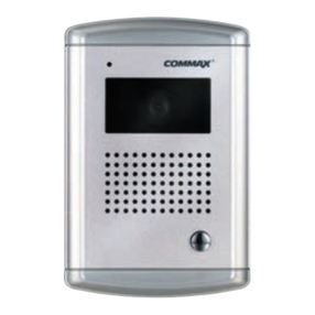
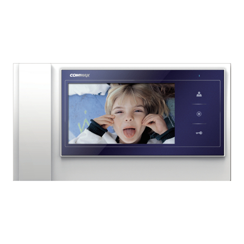
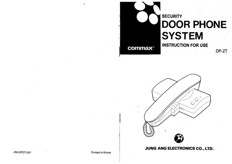
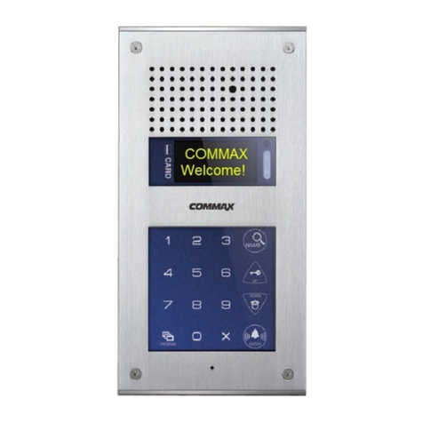
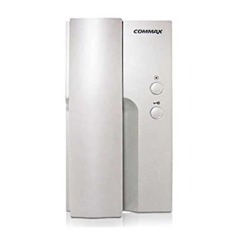
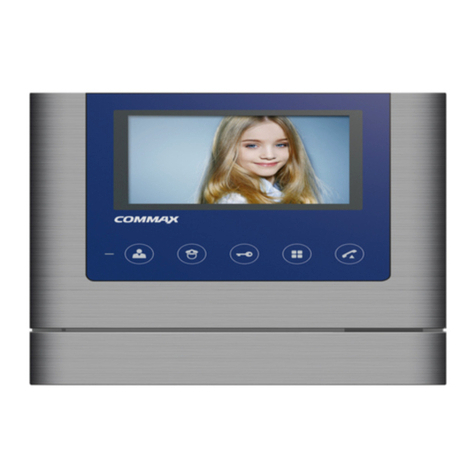
Commax CDV-40QM User manual

•Thank you for purchasing COMMAX products.
•Please carefully read this User’s Guide (in particular, precautions for safety) before using a product and follow
instructions to use a product exactly.
•The company is not responsible for any safety accidents caused by abnormal operation of the product.
513-11, Sangdaewon-dong, Jungwon-gu, Seongnam-si, Gyeonggi-do, Korea
Int’l Business Dept. Tel. : +82-31-7393-540~550 Fax. : +82-31-745-2133
Web site : www.commax.com
•Thank you for purchasing COMMAX products.
•Please carefully read this User’s Guide (in particular, precautions for safety) before using a product and follow
instructions to use a product exactly.
•The company is not responsible for any safety accidents caused by abnormal operation of the product.
Color video door phone CDV-40QM
User Manual

●Thank you for choosing COMMAX.
●Please read this manual carefully before you use the product.
MEMO.
Greetings ..................................................................................................................1
Contents table...........................................................................................................1
1. Warnings and caution ...........................................................................................2
2. Part names and functions .....................................................................................4
3. How to use the products .......................................................................................6
4. Settings ................................................................................................................8
5. Installation ..........................................................................................................18
6. Wiring .................................................................................................................19
7. Parts list .............................................................................................................21
8. Specification....................................................................................................... 22
9. Caution in use ................................................................................................... 22
10. Miscellaneous ..................................................................................................22
Greetings
Table of contents
1

2
Please follow the things described below in order to prevent any
danger or property damage.
Warning
Caution
Prohibition.
No disassembly
No touch
Must follow strictly.
Shows plugging out the power cord
without an exception
Shows the warning and caution for an electric shock.
Shows the warning and caution for a fire.
It may cause a minor damage or injury if violated.
It may cause a serious damage or injury if
violated.
Power & Installation
Warning
Please don’t use several
products at the same time on
one power socket.
·It may cause a fire due to an
abnormal overheating.
Please don’
tbend the power
cable excessively or it may
cause an electric shock.
·fire when using a damaged
power cable.
Please don’
t handle the power
cable with a wet hand.
·It may cause an electric
shock.
Please plug out the power
cable from the socket when
not using it for a long period
of time.
·It may shorten the product
lifespan or cause a fire.
Please don’t install the
product in the place where
there is much oil, smoke or
humidity.
·It may cause an electric
shock or fire.
Please don’t install the
product with the lightening
and thunder.
·It may cause an electric
shock or fire.
Please don’
tuse and connect
this product with other
products with different rated
voltage
·It may cause a disorder or
fire.
When installing the product
that generates heat, please
install the product away from
the wall (10cm) for the
ventilation.
·It may cause a fire due to
the increased internal
temperature.
1. Warnings and caution

3
Cleaning & Use
Please don’tdisassemble,
repair or rebuild this product
arbitrarily (please contact the
service center if a repair is
needed.
·It may cause an electric
shock or fire.
Please plug the power cable
firmly into the inner end
·It may cause a fire.
Please hold the plug tightly
when unplugging the power
cable (a part of the copper
wire may be disconnected if
the grabbing is only made on
the cord when pulling out the
cable).
·It may cause an electric
shock or fire
When connecting the power
cables after cutting the cable,
please install the product with
power off
·It may cause an electric
shock or fire
When installing the product,
please fix it firmly while using
the wall-mounting unit and
screws.
·It may cause an injury from
the falling object.
Please be careful when using
an AC circuit breaker since
there is a possibility of an
electric shock.
When cleaning the product,
please rub it with a soft and
dry cloth after plugging out
the power cable. (Please don’
t
use any chemical products
such as wax, benzene, alcohol
or cleanser.)
Please don’t drop the product
on the ground and don’
tapply
a shock .
·It may cause a failure.
Please use the designated
connection cable within the
maximum calling distance
designated for the product
·It may reduce the product
performance.
Please check the use voltage
and current for the DC-only
products and use the
appropriate rectifier.
·It may cause a fire.
Please avoid direct rays of the
sun or heating devices at a
time of installation.
·It may cause a fire.
Please don’t install the
product on an unstable place
or small support board.
·It may cause an injury if it
falls down while in use.
Ifan abnormal sound, burning
smell or smoke is coming out
of the product, please plug out
the power cable and contact a
service center.
·It may cause an electric
shock or fire.
Please don’t insert any
metallic or burnable materials
into the ventilation hole.
·Itmay cause an electric
shock or fire.
Please use only the designated
batteries for the products of
using DC power.
·It may cause an electric
shock or fire.
Cleaning & UsePower & Installation
Warning
Caution
4
Contents
1
2
3
4
5
6
Monitor
Monitor button
Mike
Interphone button
Call Volume
Tones Volume
7
8
9
10
11
12
Micro SD Card
[T-FLASH] slot
Open Door Button
Talk Button
External Connections
MENU button
SELECT Button
UP button
DOWN button
Power switch
Speaker
Contents ContentsNo. No. No.
2. Part names and functions
1. Monitor
2. Monitor Button : It can be used to see images from the camera.
3. Mike
4. Interphone Button : It will be used to call interphone.
5. Call Volume : You can control call volume while the call
6. Ring tone volume : It is used to adjust the ring tone
7. Menu Button : Use the menu on the entry
8. SELECT Button : Press to select an item from the menu.
9. UP button : It is used to move from the menu items up and right
If there are too many files in the list, press UP button for a while to move to previous
page
10. DOWN button : It is used to move from down and left.
If there are too many files in the list, press DOWN button for a while to move to next
page
11. Power switch : It is used to move on and off.
12. Speaker
13. Micro SD Card [T-FLASH] slot : This is insert part of Micro SD[T-FLASH].
14. Open door button : You can use open the door.
15. Talk button : It is used to talk.
16. External Connections : You can set 2 cameras.
You can set through short pin (2P), When you connect short pin you can use only
CAM1. When you open the short Pin you can use both of cameras CAM1 and CAM2.
13
14
15
16

5
※Caution
•2 Door cameras and 2 CCTV cameras
•To avoid noise on the LCD , please keep Max. space among each video line of
camerasTo avoid noise on the LCD, put 5 lines of UTP cable together and use it for
GND when UTP[CAT.5] is used for door camera.
•Regarding CCTV wiring, put all lines, except the lines for video, together and use it
for GND to avoid video noise when UTP[CAT.5] is used.
•You do not insert or take for Micro SD When you on/off power switch or take image
and save you do not insert or take because products can be critically damaged.
Please be careful. (Data in built-in memory or Micro SD may be deleted, Product
malfunction and etc...)
•Internal memory has limited capacity, if you use Micro SD and over the memory,
you should save important file and backup data as old file will be deleted first.
•For the Video Quality Guarantee saved in the memory, it should apply the Micro SD
having the conditions as bellows.
•If not, then video quality cannot be guaranteed
•Micro SD [T-FLASH] suggested Spec –Please after format use the product
1) Manufacturing : SANDISK
Micro SD : 2GByte
Micro SDHC [CLASS 6] : 4 ~ 16GByte
2) Manufacturing : TRANSCEND
Micro SD : 2GByte
Micro SDHC [CLASS 6] : 4 ~ 16GByte
3) Micro SDHC [CLASS 6] : It will be saved 400 min image when you use 4GByte.
But, the time of saving can be changed according reflected in the camera as
multiple colors and moving subject.
•In this products built in Super Cap.
Super Cap can prevent damage of the file when power cut, when switch off Super
Cap can make internal time circuit during timed.
Super Cab should be charged about 10 min and when block the power can make
time circuit during 48 hours If block the power during the saving video it can be
stopped circuit within 48hours, If supply power, you should be checked time setting.
* Please check and set because the products have time error.
•Micro SD [T-FLASH]Card insert methods
Please insert Micro SD Card as below picture and right direction.
When you insert card please insert until the sounds.

6
•If you on of the power switch, it will be displayed COMMAX logo with ring sound.
When the call came from the door camera (on time monitor 30±5sec)
①When you press the call button in the door camera, it will be displayed the visitors
images and sound tones.
②You can control call volume when ring the bell.
When you talk to the door camera (the time of off when you calling 60±5sec)
①When you call from the door camera, It will be displayed visitors image and ring
tones.
②After 60 Sec It will be closed the screen.
③It will be displayed from standby mode to image when you press the monitor button.
④If take handset of Interphone you can call with interphone while call house hold with
camera.
⑤If you close the calling, please press calling button and it will be changed standby
mode.
the function of open door
•When you press open door button It will be sound and then open the door.
If you connect entrance camera that has function of open door, It will be open the
door.
※It is same for Interphone.
Monitoring
Standby mode
- If you press the monitor button, It will be process as below.
3. How to use the products

7
- If not set CCTV mode
- Camera 1 Camera 2 OFF Camera 1 ............
- If you press the monitor button, It will be process as below.
- (If set CCTV mode)
- Camera1 Camera2 CCTV 1 CCTV2 OFF Camera1 ............
If you connect call, CCTV is not case.
- If you press the monitor button, It will be process as below
- Camera 1 Camera 2 Camera 1 Camera 2 ............
The motion of interphone connection
1. Entrance Camera with call
①If you call entrance camera it ring the bell house hold and interphone.
②If you take handset of interphone or press the talk button it will be call with entrance
camera and if you press opening button, open the door.
③While talks over interphone with camera please press the talk button you can call
with house hold also. If you take handset of interphone you can call entrance
camera, interphone.
2. Interphone with house holds call
①If you call from interphone to house hold, please take hands set of interphone and
please press the talk button and then ring the bell from house hold.
If you press call button you can call to interphone, when call form entrance while
talk over the telephone it ring the cell house hold and interphone and you can call
entrance also.
②If you call from house hold to interphone please press talk button and interphone
button When ring the call, please take handset of interphone you can call with
house hold.
CCTV connect
•When active CCTV, In case of CCTV is not function of calling and you should be
understand CCTV Image monitoring, video, capture and saving.

8
4. Settings
Brightness/Contrast/Color adjustment function
Press the MENU button on the right in a Video call / Monitoring status. And access to
Configuration menu above with △/▽(Interphone button/Talk button) button to set up
the brightness/contrast/color.
Move to each icon in the Configuration menu with △/▽(Interphone button/Talk button)
button. And enter the menu below with SELECT(Unlocking button) button.
①Brightness : adjusting brightness
②Contrast : adjusting contrast
③Color : adjusting color.
※How to adjust
①In the configuration mode of 3-1, move to the icon to set △/▽(Interphone
button/Talk button) button.
②Press the SELECT(Unlocking button) button to choose an icon.
③Adjust the set value with △/▽(Interphone button/Talk button) button.
④After choosing, complete the set with SELECT button(Unlocking button).
Screen set (Brightness/Contrast/Color adjustment function)
•Products settings need the following 4 buttons
Start Menu / Go Back : MENU Button (Monitor Button)
When you enter the menu principal you should be used side menu.
select / input : SELECT button (the button of open door)
Back to top/Move right : △(UP button) (Interphone button)
Move Down/Move left : ▽(DOWN button) (talk button)

9
How to set up
①In the configuration mode of 3-1, move to RESET icon with △/▽(Interphone
button/Talk button).
②Press the SELECT(Unlocking button) button to choose an icon.
③Select YES with △/▽(Interphone button/Talk button).
④Complete initializing the screen value with SELECT (Unlocking button) button.
Configuration
•In standby status, move to Configuration menu by pressing menu button. And move to
relevant icon with △/▽(Interphone button/Talk button).
Press the SELECT (Unlocking button) button to enter relevant menu.
MEDIA SET (Setting the saving and recording Video, Image/CAPTURE)
RESET : initializing screen set

10
⇨CAPTURE is saved up to 128 Captures.
⇨If the capacity of image file and video file exceeds, new file will be saved after
deleting from old files.
CAPTURE (AUTO)
⇨It is used when calling/ speaking over the phone. Image screen turns on and still
image is captured automatically and saved.
⇨If you press the monitor button more than 1 sec in the continuous recording status,
still image (CAPTURE) is captured and saved.
CAPTURE (MANUAL)
⇨If you press the monitor button more than 1sec when calling/ speaking over the
phone, still image (CAPTURE) is captured and saved.
VIDEO (AUTO)
⇨It is used when calling / speaking over the phone. Image screen turns on and still
image is captured automatically and saved.
When calling if you don’t receive the call, for 30 sec, if you receive the call, for 60
sec, video is recorded automatically and saved.
⇨After calling, video can be saved up to maximum 1min 30sec of talk time (30+60).
⇨In the middle of saving video, it can be saved by cancellation of calling or end of
call.
⇨If you press the monitor button more than 1 sec in the middle of recording video,
video keeps recording and separately capturing image is captured and saved.
VIDEO(MANUAL)
⇨If you press the monitor button more than 1 sec when calling/ speaking over the
phone, video is recorded and saved.
⇨If you press the monitor button more than 1 sec in the middle of recording video,
video keeps recording and separately capturing image is captured and saved.
※CCTV Video save function is only available in Manual mode. Click monitor button
more than 1 second during the monitoring. Then, video recording will be continued
about 60seconds. Please note that default video saving time is 60 seconds even
though monitoring continues as the capacity of memory is limited. When the
saving is over after 60seconds, click monitor button more than 1 second again to
restart video saving.
Managing folder and file
⇨Making basic folder
CDV-40QM\VIDEO\ ( Video storage folder )
CDV-40QM\PICTURE\ ( Capturing storage folder)
⇨When the icon is displayed please built in data or backup.

11
⇨The name of saved file and form
⇨It is necessary memory or minimum space of Micro SD Card.
Minimum space : Built in Flash – 20MByte, Micro SD – 100MByte
⇨Stop image Mix 128 cuts
If you excess capacity please eliminate old file and then save.
⇨Video can be saving in full.
(If not have any space in the memory )
If not have any space in the Micro SD Card.
It will be displayed icon in LCD screen.
When you displayed icon it will be eliminated old file
and then Video save.
You can eliminate date to secure minimum space and
please save backup Important data.
It will be disappeared “IN FULL”, “SD FULL” icon when you eliminate
the format of Micro SD Card or built in memory you can secure
minimum space You can save depend on the file qty please check
reference.
It is depend on the memory size and please see the as follow
information.
Even though you have extra saving space if excess file it will be
canceled automatically old file and save.
⇨If not have Micro SD Card you can save in the memory of products
If you insert Micro SD Card, after data backup you can save in
Micro SD. If you eliminate Micro SD Card, you can re-save in the
memory.
⇨It will be displayed descending order.
⇨It is possible whole cancel and selection cance
110516_130502_D1.jpg
110516_130502_C2.jpg
110516_130502_D1.mp4
110516_130502_L1.mp4
Date Time Video Type File Type
11/5/16 13hr5min2sec D1,D2 = Lobby 1,2 Still image (*.jpg)
C1,C2 = CCTV 1,2 Video (*.mp4)
Still image
Video
Explanation
of file
Note

12
⇨The number of saving for capacity
1. Saving route and play/deletion of Data(Video and (image/CAPTURE) :
this is a route to save (Video and image/CAPTURE) data, you can check and
delete(Optional deletion/Whole deletion) recorded(capture) video and
image/CAPTRUE by playing the data and deleting the data on the relevant route.
2. Recording Video and Image/CAPTURE set :
Video recording or image saving is executed by image or by image/capture can be
set by the users. Moreover, whether recording and saving at any time or
automatically when calling/speaking over the phone can be also set during talking.
If there is no Micro SD Card, it is saved in the internal memory of the product. When
Micro SD Card is inserted, it is stored on Micro SD Card after backup of the
product’s internal memory. If Micro SD Card is removed, it will be stored on the
product’s internal memory again.
3. FORMAT (Data format)
formatting the data of captured image and saved video of the product. (Once data is
formatted, you cannot restore. Please take it into account carefully when formatting.)
In case of Micro SD Card inserted: formatting not internal memory but Micro SD card.
In case of Micro SD card not available: formatting the internal memory of product’s
desktop.
4. INFO :
Possible to check the information of present products’ memory capacity
Capacity 100 MByte 4 GByte 8 GByte 16 GByte
Stop Image 128 128 128 128
max 100 cuts max 400 cuts max 1,000 cuts max 1,000 cuts
Video storage time 8 min 400 min 800 min 1500 min
⇨Stop image can make 128 cuts fixed. But it can be changed number of video
according the time of image and depend on the space.
⇨Size of stop image: 80 KByte
⇨Size of Video file: 10 MByte (60 second)
The number of
Video saving
(60 Second)
Internal Flash Micro SDHC Card

13
PLAY/ DELETE SELECTED FILE / DELETE ALL/ PREVIOUS PAGE
How to set up
①In the configuration mode of 3-2, move to MEDIA icon and after press the
SELECT (Unlocking button) button, move to relevant icon with △/▽(Interphone
button/Talk button)
②Press the SELECT(Unlocking button) button to choose a route.
③Select the saved data you want with △/▽(Interphone button/Talk button).
④After choosing, play and delete the data with SELECT (Unlocking button) button.
(2) Video and Image/CAPTURE picture set
(1) Saving route and play/deletion of data (Video and (image/CAPTURE))
How to set up
①In the configuration mode of 3-2, move to MEDIA icon and after press the
SELECT (Unlocking button) button, move to relevant icon with △/▽(In
button/Talk button).
②Press the SELECT(Unlocking button) button to choose an icon.

14
③Select the record (movie/still image) or not with △/▽(Interphone button/Talk
button).
④After choosing, complete the set with SELECT (Unlocking button) button.
⑤After selecting record or not with △/▽(Interphone button/Talk button), complete
the set by pressing SELECT (Unlocking button) button.
(3) FORMAT (data format): format the capture data and movie saved in a product.
How to set up
①In the configuration mode of 3-2, move to MEDIA icon and after press the
SELECT (Unlocking button) button, move to FOMET icon with △/▽(Interphone
button/Talk button).
②Press the SELECT (Unlocking button) button to choose an icon.
③Select the FORMET set acceptance or rejection with △/▽(Interphone
button/Talk button).
④After choosing, complete the set with SELECT button(Unlocking button)
(4) INFO (checking memory capacity information of present items)
Possible to check memory capacity information of present items.
IN : remaining capacity/total capacity –indicates the information of buit-in memory
capacity.
Micro SD : remaining capacity/total capacity –- indicates capacity information of Micro
SD card.

15
How to set up
①In the configuration mode of 3-2, move to UTILITY icon and after press the
SELECT(Unlocking button)button, move to LED DIMMING icon with △/▽
(Interphone button/Talk button).
②Press the SELECT(Unlocking button) button to choose an icon.
③Select the desired mode with △/▽(Interphone button/Talk button).
④After choosing, complete the set with SELECT button(Unlocking button).
UTILITY
(1) LED DIMMING : Stand-by status of the product on
①No.1 mode : Call LED repeats bright status and dark status.
②No.2 mode : All LED change bright status to dark status repetitiously.
③No.3 mode : In consecutive order from monitor button to Talk button, it changes
bright status to dark status repetitiously.

16
(2) CHIME-BELL MUTE : Setting mute sound.
How to set up
①In the configuration mode of 3-2, move to UTILITY icon and after press the
SELECT(Unlocking button)button, move to CHIME-BELL Mute icon with △/▽
(Interphone button/Talk button).
②Press the SELECT(Unlocking button) button to choose an icon.
③Select the mute sound or not with △/▽(Interphone button/Talk button).
④After choosing, complete the set with SELECT button(Unlocking button).
(3) Time setting: Set the time of products. (It is used videos and image saving)
Setting
①It will be moved the UTILITY icon from establishment of Environmental 3-1 and
please after press the button of SELECT You can move the setting icon when you
use the interphone and talk button △/▽
②Please press the SELECT button and you can select items.
③You can set time of households when you use the interphone and talk button △/▽
④When you input the time please press the [OK] button and SELECT button and then
it will be finished.

17
(4) CCTV setting
: Users can set CCTV on or off up to 2, if not activating, CCTV can not be connected.
How to set up
①In the configuration mode of 3-2, move to UTILITY icon and after press the
SELECT(Unlocking button) button, move to CCTV activation icon with △/▽
(Interphone button/Talk button).
②Press the SELECT(Unlocking button) button to choose an icon.
③Select CCTV on or off with △/▽(Interphone button/Talk button).
④After choosing, complete the set with SELECT button(Unlocking button).
INFORMATION (Product information such as)
Possible to check the information of the product such as name of product, version,
etc Model : Model name
(5) Version : The version of the product

18
2. Installation Method of camera
Note
①Do not install the camera where
it is exposed to Direct sunlight
②Keep cleaning up its lens to
capture good views.
SCREW T4X18(2EA)
SCREW M3X8(1EA)
DRC-40CK
1. Installation Method of camera monitor
Note
①Avoid the range of direct sunlight
②Recommended height is pertinent
from 1450 ~ 1500mm
③Avoid the installation near magnetic
activity, humid temperatures and gas
5. Installation
Please coil the Cable connector
(CAMERA1,CAMERA2,
INTERPHONE, CCTV1, CCTV2)
around the core that is packed in
accessory bag like below image first
and connect them to the product.

19
①RED : Audio ②BLUE : GND ③YELLOW : POWER(+12V) ④WHITE : VIDEO
Caution on the Wiring
Be sure to use a separate wiring for each connect 2 UTP CABLE[CAT.5] are
required if UTP CABLE[CAT.5] is used for CAMERA1 and CAMERA2 and
Interphone UTP CABLE[CAT.5] If 3 UTP CABLE[CAT.5]
For better picture quality, We recommend using 5 lines for GND if UTP
CABLE[CAT.5] is used
Camera connector polarity
CCTV CAMERA 1 CCTV CAMERA 2
6. Wiring
Table of contents
Other Commax Intercom System manuals

Commax
Commax DP-20H User manual

Commax
Commax DP-20H User manual

Commax
Commax DRC-40CK User manual

Commax
Commax CDV-70A User manual

Commax
Commax CDV-43KM User manual

Commax
Commax CDV-72UM User manual

Commax
Commax DRC-7MBL/RF1 User manual

Commax
Commax CDV-70QT User manual

Commax
Commax CAV-70HS User manual

Commax
Commax CAV-51M User manual

Commax
Commax DRC-MSB User manual

Commax
Commax DPV-4MTN User manual

Commax
Commax DR-2A3N User manual

Commax
Commax CM-800 User manual

Commax
Commax WT-171LM User manual

Commax
Commax DRC-4CPN2 User manual

Commax
Commax AP-2SAG User manual

Commax
Commax DRC-4CPN2 User manual

Commax
Commax CAV-70MHG User manual

Commax
Commax DR-2R User manual