COEF EMULATION CTC User manual

EMULATION CTC
OPERATION MANUAL
Document No: OM-L2010-001-R01

PAGE 2
COEF EMULATION CTC
TABLE OF CONTENTS
DECLARATION OF CE CONFORMITY ------------------------------------------------------------------------------------------------------ 3
ADVICES FOR A CORRECT INSTALLATION----------------------------------------------------------------------------------------------3
GENERAL WARRANTY CONDITIONS------------------------------------------------------------------------------------------------------- 4
PACKING CONTENTS---------------------------------------------------------------------------------------------------------------------------- 4
WIRING BASICS------------------------------------------------------------------------------------------------------------------------------------ 4
1. INTRODUCTION -------------------------------------------------------------------------------------------------------------------------------- 5
2. OPERATION-------------------------------------------------------------------------------------------------------------------------------------- 5
2.1 DMX TABLE ----------------------------------------------------------------------------------------------------------------------------- 6
2.2 BACK PANEL --------------------------------------------------------------------------------------------------------------------------- 6
2.3 MENU STRUCTURE ------------------------------------------------------------------------------------------------------------------ 7
3. APPLICATIONS EXAMPLE ------------------------------------------------------------------------------------------------------------------ 8
3.1 MANUAL DMX ADDRESSING ----------------------------------------------------------------------------------------------------- 8
3.2 AUTO ID (DMX) ADDRESSING---------------------------------------------------------------------------------------------------- 8
3.3 MANUAL DMX AND AUTO ID ADDRESSING I-------------------------------------------------------------------------------- 8
3.4 MANUAL DMX AND AUTO ID ADDRESSING II------------------------------------------------------------------------------- 8
4. TROUBLESHOOTING ------------------------------------------------------------------------------------------------------------------------- 9
5. TECHNICAL SPECIFICATIONS ------------------------------------------------------------------------------------------------------------ 9
GENERAL NOTES

PAGE 3
COEF EMULATION CTC
ADVICES FOR A CORRECT INSTALLATION
This equipment is designed to an exclusively Professional use.
1) Make sure that all the fastening parts of the spotlight are in good condition. Regulate the proportions of the fasten-
ing accessories (screws, bushes, nuts, supports, etc.) in order to be slightly over-dimensioned as compared to the
actual requirements.
2) The installation must always be secured with a secondary safety attachment, e.g. an appropriate catch net. The
secondary safety attachment must be constructed in a way that no part of the installation can fall down if the main
attachment fails.
3) Carefully check the contents of the packaging and the completeness of the components. If any of the parts listed
hereunder is missing, please contact your Dealer immediately.
4) Do not install the projector outside where the influence of atmospheric factors could damage the unit working
(rain, wind, intense heat etc.) or indoor if there is a high percentage of humidity.
5) Do not clean the projector using water jets or immersion in different liquids. Scrupulously follow the indications
given in the chapter MAINTENANCE.
6) Make the electric connections and the installation / replacement of the lamp after having disconnected the power
supply and after had positioned the power switch to OFF. The apparatus is classified as belonging to Class 1 type
of protection against electric shocks. Its connection to an earthed mains unit is compulsory. The equipment must
be protect by an degusted magneto-thermal switch. You are recommended to equip the system with aptly dimen-
sioned differential switches.
7) Do not touch in any case the internal and external parts of the projector without previous authorization of the con-
structor and make modifications only by the intervention of qualified staff.
8) If the bulb explodes, the particular design of the apparatus prevents the splinters from going outside the projector.
All the parts, therefore, shall be complete and perfectly assembled. The lenses, if visibly damaged, shall be re-
placed by original spare parts.
9) Minimum distance from illuminated objects: The projector must be positioned in such a way that objects struck
by the light beam are located at least 1 meters from the projector objective.
10) Minimum distance from inflammable materials: 0.5 meters
DECLARATION OF CE CONFORMITY
We Manufacturer IAG Sanecore Science & Technology Industry Park, Jiuwei Village, Xixiang Town, Shenzhen, China,
518102 Declare that the product EMULATION CTC is in conformity with 89/336 EEC-EMC directive and with the actual
required safety standards in accordance with LVD 73/23 EEC
Shenzhen, 01 August 2010
ATTENTION: carefully read the directions of this manual. Exclusively follow the safety rules in force and do not carry
out assembly and/or maintenance operations without taking all precautions as indicated in the different sections or with-
out the necessary specialization.
This manual must always accompany the equipment, therefore it must be available and readable at any moment if nec-
essary. Also in case of sale, rent, change of place and/or ownership, these documents shall be enclosed with the rela-
tive equipment.
PAGE 4
COEF EMULATION CTC
11) MAX ambient temperature: 60° C.
12) MAX external surface temperature: 60° C.
13) Don’t look directly the lamp trough the lens.
14) We recommend not to look at the lamp without wearing a proper protection; also ensure that the covers are as-
sembled to the equipment.
15) Inside the equipment there are high temperatures and tension/current values which might be very dangerous. It is
necessary to disconnect the equipment from the mains before removing its protection covers and wait for 30 min-
utes at least before touching any part inside.
16) Do not switch on the equipment if its lamp is not inserted.
17) Leave sockets and air outlets free from encumbrances and clean them periodically (see “Maintenance” section).
18) Do not leave the packaging elements (polystyrene, nylon, metal parts, etc.) unattended; they might be dangerous
for children.
This manual has been organized in order support the user, the installer or the maintenance operator of the described
unit with those necessary in formations for a correct use of the installation and working procedures of the same unit.
The various procedures will be just signaled by indicators (when necessary) evidencing the operation dangers and the
necessity of technical support.
GENERAL WARRANTY CONDITIONS
• The guarantee is valid for a period of 12 months from the date of equipment delivery.
• The guarantee is not valid in case a wrong voltage or frequency is selected.
• The parts which are proved to have manufacturing defects are also covered by the guarantee.
• The external parts of the equipment, its removable elements and lamps are excluded from the guarantee; for
these parts we recommend to follow the directions supplied by their manufacturers.
• The guarantee is not valid in case of tampering or repairs carried out by non-authorized personnel.
• The replacement of the equipment during the validity of the guarantee is not provided for.
• The transport freights from and to the manufacturer for repairs under guarantee are at Customer’s charge.
• When applying for the repair, always mention the serial number and the model of the equipment.
PACKING CONTENTS
• Complete EMULATION CTC unit
• This user manual
• 1 AC Power cord
WIRING BASICS
Connection with the mains
Connect the device to them mains with the power plug. The occupation of the connection cables as follows:
Cable Pin International
Brown Live L
Blue Neutral N
Yellow Earth E
European Standard
Cable Pin International
Black Live L
White Neutral N
Green Earth G
American Standard
∗ The earth must be connected!

PAGE 5
COEF EMULATION CTC
DMX-512 connection/ connection between fixtures
The wires must not come into contact with each other, otherwise the fixtures will not work
at all, or will not work properly.
Please note, the starting address depends upon which controller is being used.
Only qualified shield cable (Belden 9841 or Belden 9842 is recommended) and 3-pin XLR plugs and connectors in or-
der to connect the controller with the fixture or one fixture with another.
Occupation of the XLR connection:
DMX Output
XLR mounting socket DMX input
XLR mounting plug
If you are using controllers with this occupation, you can connect the DMX output of the controller directly with the DMX
input of the first fixture in the DMX chain. If you wish to connect DMX controllers with other XLR outputs, you need to
use adapter cables.
Building a serial chain:
Connect the DMX output of the first fixture in the DMX chain with the DMX input of the next fixture. Always connect on
output with the input of the next fixture until all fixtures are connected.
Caution:
At the last fixture, the DMX cable has to be terminated with a terminator. Solder a 120Ωresistor between signal (+) and
signal (-) into 3-pin XLR plug and plug it in the DMX output of the last fixture.
1. INTRODUCTION
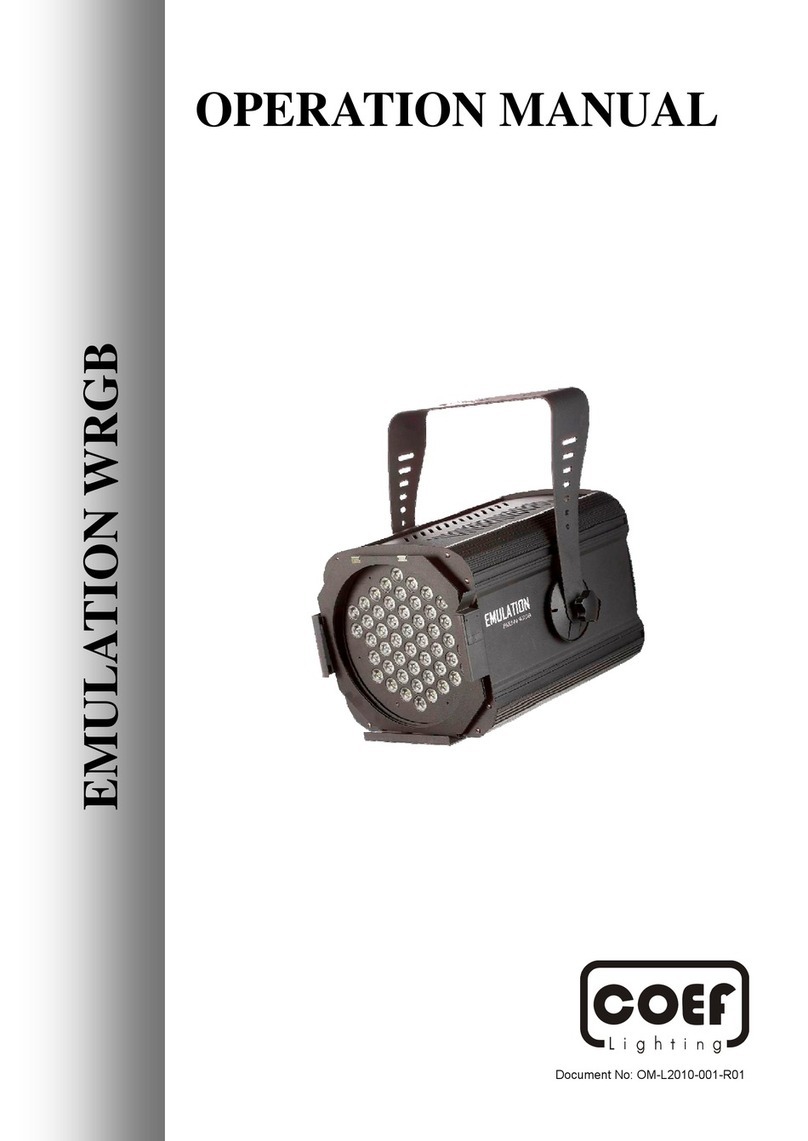
EMULATION CTC is a spotlight with continuously color temperature adjustment and optional projection angle, it’s a
perfect fixture to replace conventional PAR 64 spotlight.
With the ground breaking design, EMULATION CTC offer following advanced features:
• Adjustable color temperature from 3,300°K to 8,000°K.
• Four optics are available on request: 45º, 60º, 90º, 120º.
• 200 lm high power 3W LED.
• Universal power supply
• Constant voltage/ current drive control.
• Speed of ventilation fan adjust by temperature changing
• Automatic recovery protection from over load, over temperature.
• Automatic/ manual DMX addressing. (AUTO ID Function)
• High tech and patented material offer the best ventilation.
1: Ground
2: Signal (-)
3: Signal (+)
1: Ground
2: Signal (-)
3: Signal (+)
2. OPERATION
The setup of EMULATION CTC is very easy via related keypads with necessary information shows on the display. Also
with two LEDs indicating the operation status. Please refer to following instructions.

PAGE 6
COEF EMULATION CTC
2.1 DMX TABLE
CHANNEL NO. FUNCTION CHANNEL NO. FUNCTION
Channel 1 White dimmer 0 - 100% Channel 2 Warm white 0 - 100%
Adjustable color temperature from 3,300°K to 8,000°K, 4,850°K when both channels reached 100% of DMX value.
2.2 BACK PANEL
DMX IN
AUTO ID LINK
DMX OUT
AUTO ID is very useful function that device doesn’t need to address DMX channel manually. Since the first device
setup the DMX address, rest of devices archived their own unique ID automatically. Benefit is less installation time, and
DMX address conflict free.
For using AUTO ID devices only or mix with NON AUTO ID devices, please refer to the chapter “Applications Exam-
ple”.

PAGE 7
COEF EMULATION CTC
2.3 MENU STRUCTURER
MENU
DOWN –1
UP + 1
DMX AUTO ID OFF
ENTER
ENTER
DMX AUTO ID ON
COLOR CHANGE
DMX 2 CHANNEL
COLOR CHANGE
DMX AUTO ID OFF
COLOR CHANGE
DMX AUTO ID ON
COLOR CHANGE
DMX MANU ID 001
COLOR CHANGE
DMX MANU ID 000
COLOR CHANGE
DMX MANU ID 512
MANU COLOR ON
WARM W DIMMER 255
MANU COLOR ON
WARM W DIMMER 000
MANU COLOR ON
COOL W DIMMER 255
MANU COLOR ON
COOL W DIMMER 000
COLOR CHANGE
DMX MANU ID 001
COLOR CHANGE
NOT ID 001 OFF
UP/DOWN
ENTER
COLOR CHANGE
DMX MANU ID 001
COLOR CHANGE
NOT ID 001 ON
UP/DOWN
ENTER
COLOR CHANGE
MANU COLOR OFF
COLOR CHANGE
MANU COLOR ON
UP + 1
DOWN - 1
UP + 1
DOWN - 1
(INITIAL DISPLAY)
(SETTING
UP
DMX AUTO
ADDRESSING FUNCTION)
(IF DMX AUTO ID IS ON, DMX MANU ID WILL BE REMAIN 000)
(USING UP/DOWN KEY TO SELECT DMX START ADDRESS)
(SETTING UP COLOR MANUALLY)
(HIGHER DMX LEVEL, MEANS HIGHERCOLOR TEMPERATURE)
(SETTING
UP
DMX ADDRESS MANUALLY)
Note 1:
The LED display will blinking twice after pressing
ENTER key, that’s means the setup is complete.
Note 2:
The function of “NOT ID 001 ON” is using in the
system mix with AUTO ID and NON AUTO ID
devices. Please refer to the next page
“Application Examples”.
(SETTING
UP MIXED AUTO ID AND NONAUDO ID DEVICES, )
UP/DOWN

PAGE 8
COEF EMULATION CTC
3. APPLICATIONS EXAMPLE
3.1 MANUAL DMX ADDRESSING
DMX Controller
DMX MANU ID 001
Channel 1-2
DMX MANU ID 003
Channel 3-4
DMX MANU ID 005
Channel 5-6
DMX MANU ID 007
Channel 7-8
3.2 AUTO ID (DMX) ADDRESSING
DMX Controller
DMX AUTO ID ON
Channel 1-2
DMX AUTO ID ON
Channel 3-4
DMX AUTO ID ON
Channel 5-6
DMX AUTO ID ON
Channel 7-8
3.3 MANUAL DMX AND AUTO ID ADDRESSING I
DMX Controller
Example
Channel 1-8
DMX AUTO ID OFF
DMX Manu ID 09
NOT ID 001 ON
Channel 9-10
DMX AUTO ID ON
Channel 11-12
DMX AUTO ID ON
Channel 13-14
NON AUTO ID
Device
3.4 MANUAL DMX AND AUTO ID ADDRESSING II
DMX Controller
Example
Channel 1-8
DMX AUTO ID ON
Channel 11-12 Example
Channel 13-19
DMX AUTO ID OFF
DMX Manu ID 20
NOT ID 001 ON
Channel 20-21
DMX AUTO ID ON
Channel 22-23
NON AUTO ID
Device
NON AUTO ID
Device
DMX AUTO ID OFF
DMX Manu ID 09
NOT ID 001 ON
Channel 9-10

PAGE 9
COEF EMULATION CTC
5. TECHNICAL SPECIFICATIONS
Power Supply: 100-240V/AC, 50/60HZ
Power Consumption: 150W
LED Power: 144W
LED Source: 24 * 3W CW-LED
24 * 3W WW-LED
Luminous flux: W/3W=200 lum/ 8000°K
Optional Optics: 45º/ 60º/ 90º/ 120º
Maximum Ambient Temperature: 0°C to 60°C
Maximum Housing Temperature: 80ºC
Chassis Material: Die cast aluminum body
Protection: IP20
DMX Channel 2 Channel
Dimension (L * W * H): 294mm * 362mm * 344.5mm
Weight: 4.5Kg
4. TECHNICAL SPECIFICATIONS
To ensure the reliability of the spotlight it should be kept clean. It is recommended that the fan should be clean every 15
days with compressed air and in case of more resistant dirt with one soft brush.
Shall any malfunction occurred, please try following solutions.
PROBLEM POSSIBLE SOLUTION
The spotlight does not start Check the power connections
The spotlight does not respond to the controller Check the DMX cable connections, DMX address, Auto ID
and signal indication LED status. Make sure that they are
all proper addressed.
The spotlight does not work or work not properly. Check the DMX cable connections and DMX address.
Make sure that the spotlight is not in the demo or sound
activated mode.
Color does not match the assigned channel. Check the DMX channel related color.

PAGE 10
COEF EMULATION CTC

®
Sanecore Science & Technology Industry Park, Jiuwei Village, Xixiang Town, ShenZhen, China 518102
All rights reserved © 2010 COEF. COEF is a member of the International Audio Group.
Table of contents
Other COEF Lighting Equipment manuals

COEF
COEF MASTERSHOW 512 User manual

COEF
COEF EMULATION WRGB User manual

COEF
COEF MP 150 SPOT DV User manual

COEF
COEF PERFORMANCE 250DV DVP User manual

COEF
COEF Sirio 1800DV User manual

COEF
COEF 02a018 User manual

COEF
COEF EMULATION STROBE User manual

COEF
COEF MP 700 ZOOM User manual

COEF
COEF Sirio RAY 1200 02B014 User manual

COEF
COEF MP 700 WASH User manual
Popular Lighting Equipment manuals by other brands

luminii
luminii Kendo Closet Rod installation instructions

Easylife
Easylife EL6385 instruction manual

Cooper Lighting
Cooper Lighting Sure-Lites LEM installation instructions

Pfannenberg
Pfannenberg Quadro-LED HI Instructions for operating and installation

TILLYTEC
TILLYTEC MAXI UNI user manual

MULTIQUIP
MULTIQUIP GBX24BK Operation manual