COEF 02a018 User manual

Revision 3
•OPERATING INSTRUCTIONS
Realiting by PC CAD & VIDEO
COEF srl.
Via Albinatico, 80-82
51019 Ponte Buggianese (PT)
ITALY
www.coef.it / www.coef.net
PERFORMANCE 1200 DVP
•Code 02A018

COEF srl. Via Albinatico, 80-82 Ponte Buggianese 51019 ( Pistoia ) ITALY
tel. (+39) 0572-636536 r.a. Fax (+39) 0572 - 636535
Tutti i diritti di riproduzione, diffusione del presente manuale sono riser-
vati a COEF srl.
Le descrizioni ed illustrazioni fornite nella presente pubblicazione non
sono impegnative.
COEF srl. si riserva il diritto di apportare in qualsiasi momento tutte le
modifiche che riterrà opportune.
Il presente manuale non può essere ceduto in visione a terzi senza spe-
cifica autorizzazione scritta dalla COEF srl.
All rights for reproduction of this catalogue are reserved for COEF srl.
Descriptions and illustrations are not binding.
COEF srl. reserves the right to make all necessary modifications at any
time. This manual can not be inspected by third party, without written autori-
zation by COEF srl.
Les droits de reproduction de ce catalogue sont entiérement réservés à
la Société COEF srl.
Les descriptions et les illustrations fournies dans ce manuel n’engagent
acunement notre Société.
COEF srl. se réserve le droit d’apporter, à tout moment, les modifica-
tions qu’elle jugera utiles.
Ce manuel ne peut être remis à des tiers sans l’autorisation préalable de
la Société COEF srl.
Alle Rechte vorbehalten. Nachdruck verboten.
Die in diesem Handbuch enthaltenen Beschreibungen und Abbildungen
sind nicht verbindilich.
Die Firma COEF srl. behält sich das Recht auf Änderungen zu jedem
Zeitpunkt vor.
Diese Bedienungsanleitung darf ohne schriftliche Genehmigung der Fir-
ma COEF srl. dritten Personen nicht zugänglich gemacht werden.

INDEX
1.0 HOW TO USE THE MANUAL ..........................................................................................................
1.1 Installation & Security................................................................................................................
2.0 IINSTALLATION ...............................................................................................................................
2.1 Lamp mounting and re-lamping .................................................................................................
2.2 Mirror mounting or replace .........................................................................................................
2.3 Machine mounting ...................................................................................................................
2.4 Advices for a corret installation....................................................................................................
3.1 POWER SUPPLY CONNECTION . .....................................................................................................
3.1 DMX 512 CONNECTION ...........................................................................................................
4.0 SPECIAL FUNCTIONS AND PROJECTOR ASSIGNMENT.............................................................
4.1 MENU & FUNCTIONS................................................................................................................
5.0 CHANNELS AND DIGITAL VALUES ................................................................................................
6.0 FOCUS ADJUSTMENT ......................................................................................................................
7.0 GOBOS REPLACEMENT ................................................................................................................
8.0 ORDINARY MAINTENANCE ...........................................................................................................
8.1 EXTRAORDINARY MAINTENANCE ......................................................................................
8.2 ELECTRONIC MAINTENANCE ..............................................................................................
9.0 TROUBLESHOOTING ......................................................................................................................
10.0 CONFORMITY DECLARATION ....................................................................................................
11.0 TECHNICAL NOTES ....................................................................................................
12.0 ELECTRIC DIAGRAM ............................... ...................................................................................
13.0 DIMENSIONS ..................................................................................................................................
14.0 PARTS ASSEMBLY .......................................................................................................................
pag. 4
pag. 4
pag. 5
pag. 5
pag. 5
pag. 6
pag. 6
pag. 7
pag. 7
pag. 8
pag. 9
pag. 10
pag. 11
pag. 12
pag. 12
pag. 13
pag. 13
pag. 14
pag. 15
pag. 16
pag. 16
pag. 17
pag. 18
pag. 19
pag. 20

We recommend you read the entire manual very carefully, particularly the sections concerning correct
installation and safety procedures. This manual is an integral part of the supplied apparatus, therefore you are
requested to keep it with care for future reference.
This manual has been organized in order support the user, the installer or the maintenance operator of the de-
scribed unit with those necessary informations for a correct use of the installation and working procedures of the
same unit.The various procedures will be just signalled by indicators (when necessary) evidencing the operation
dangers and the necessity of technical support.
Please find here below a list of symbols and relative meaning:
OPERATOR : Not particulary qualified staff, that can operate when no specific knowledge is required
COEF OPERATOR: Technical staff, qualified and trained by the constructor, for repair and extraordinary
operations.
MECHANICAL OPERATORS: Staff employed in the ordinary mechanical maintenance.
ELECTRIC OPERATORS: Staff employed in the ordinary electric maintenance.
SPECIALIZED MECHANICAL OPERATOR: Qualified staff employed in extraordinary authorized in-
stallations and repair.
SPECIALIZED ELECTRIC OPERATORS: Qualified staff employed in extraordinary authorized instal-
lations and repairs.
DANGER SIGNAL: Generic danger signal and electric shock danger signal .
1.0 HOW TO USE THE MANUAL
1) Make sure that all the fastening parts of the spotlight are in good condition. Regulate the proportions of the fastening acces-
sories (screws, bushes, nuts, supports, etc.) in order to be slightly over-dimensioned as compared to the actual requirements.
2) Do not install the projector outside where the influence of atmospheric factors could damage the unit working (rain, wind,
intense heat etc.).
3) Do not clean the projector using water jets or immersion in different liquids. Scrupulously follow the indications given in the
chapter MAINTENANCE.
4) Make the electric connections and the installation / replacement of the lamp after having disconnected the power supply and
after haved positioned the power switch to OFF.The apparatus is classified as belonging to Class 1 type of protection against
electric shocks. Its connection to an earthed mains unit is compulsory. You are recommended to equip the system with aptly
dimensioned differential switches.
5) Do not touch in any case the internal and external parts of the projector without previous authorization of the constructor
and make modifications only by the intervention of qualified staff.
6) Make sure that the projector is correctly fixed on the support as indicated in par.2.3.
7) If the bulb explodes, the particular design of the apparatus prevents the splinters from going outside the projector. All the
parts, therefore, shall be complete and perfectly assembled. The lenses, if visibly damaged, shall be replaced by original spare
parts.
8) Minimum distance from illuminated objects: The projector must be positioned in such a way that objects struck by the
light beam are located at least 2 metres from the projector objective.
9) Minimum distance from inflammable materials: 0.1 meters
10) MAX ambient temperature: 38° C.
1.1 ADVICES FOR A CORRECT INSTALLATION
2mt.

2.0 INSTALLATION
The constructor is not be considered responsible in case of:
•Improper use fo the unit or use by not trained staff
•Use in contrast with the directions on work safety
•Wrong installation
•Defective power supply
•Serious lacks in the necessary maintenance
•Unauthorized modifications and interventions
•Use of spare parts that are not original or not specific for the unit
•Toatl or partial inobservance of instructions
•Unusual events
The lamp must be changed if damaged or deformed by heat.
WARNING: switch off the projector before operating.
Read carefully the lamp builder’s instructions.
2.1 LAMP MOUNTING AND REPLACING
The units mounts high pressure lamp with external traditional striker.
Wait at least 10 minutes af-
ter the projector has been swit-
ched off before operating
again, in order to let it cool
down and avoid the lamp ex-
plosion.
Wait 20 minutes in case
you are operating with the bare
hands in order to avoid burns.
Remove the projector cover by
backing the A screws off. Loosen the lamp’s escutcheons (part. B) hand house the lamp in the lampholder (part. C).
Put the projector cover back and screw up the Ascrews.
ATTENTION! A lamp safety cut-off is activated when the cover is not correctly closed.
Remove the elastic band
that’s blocking the motor of scansion group. For the mirror replacement (C), screw the two screws (B) and remove
the broken mirror. Install the new spare part (its support is already mounted by the factory) on the motor A, carefully
closing, using an hexagonal screwdriver.
WARNING! The mirror is very delicate, so you must handle it with great care.
2.2 MIRROR MOUNTING OR REPLACEMENT

2.3 MACHINE INSTALLATION
To fix the PERFORMANCE 1200 DVP is necessary, when the installation has to be on a raised-
from-the ground support, to block the fixing bracket of the unit by means of a screw provided with nut and
locknut measuring not less than M10X50, to insert in the central pre-arranged hole on the fixing bracket.
In order to guarantee a necessary security and in respect of the actual safety rules concerning the
projectors’ installation, it is compulsory to install a safety-chain (or steel cable), equipped with spring
clips, to connect the PERFORMANCE 1200 DVP‘s body to the fixing structure.
ATTENTION: the safety-chain must be properly installed and fixed to the supporting structure, in a
way that an incidental givin in of the main bracket would leed to the shortest possible fall of the projector.
After such an intervention the safety-chain must be replaced.
ATTENTION: COEF is not responsible for installations not correctly made or made without respec-
ting the above indications: those installations are considered dangerous.
When you need to disassemble the fixing bracket of the PERFORMANCE 1200 DVP, refer to figure
to re-assemble correctly the bracket with all its components, without damaging its functionality and secu-
rity.

3 - CONNECTIONS
3.1 - Power supply connections
WARNING: In order to guarantee the utmost safety, connect the apparatus only to a
properly earthed mains system. The projector is designed to work at the tension and
frequency indicated by the electrical data label on the rear. Before connecting the projector
to the mains, a qualified electrician must check its conformity. Should there be different
electrical characteristics or special steps to be carried out, please contact COEF by
Supply the projector by connecting it as indicated in picture.
Power supply: 200-240 V. 50-60 Hz. with voltage and frequency as indicated on the
rear of the projector
Power absorbed: 1500 VA 6.3 A with nominal voltage
S/N CHECK S/N CHECK S/N CHECK
PHASE
GROUND
NEUTRAL
3.2 - DMX 512 Connection
Connect the projector and the control unit to a wire in conformity with the EIA RS-485
standards: braided bipolar, shielded, 120 ohm of characteristic impedance, 22-24 AWG,
equipped with Cannon 3 Pin XRL plugs. Respect the DMX 512 signal input and output
according to the panel indications. A terminal pin with 120 ohm resistance (¼ Watt
minimum) must be inserted between the terminals 2 and 3 in the last piece of apparatus.
S/N CHECK S/N CHECK S/N CHECK
FROM CONTROL UNIT

On switching the projector on, the display will indicate the type of projector and the version of control software
which have been installed. To this purpose, please remember that this type of projector belongs to a new generation
of projectors, designed with the possibility of updating the software version through the normal DMX connection by
means of a programmer deliberately created: UNI-PROG 8.
After the indication MSTR HOME, the projector carries out the RESET and gets ready to be controlled from the
connected console.
The display will indicate 1 as default value. This means that the first channel occupied by the projector will re-
spond to the values sent to channel 1 by the DMX line. This also means that according to the total number of chan-
nels assigned to the projector by means of the CH89 function, MISC menu (see Table 4.1 Menu/Fuctions), we shall
be able to check the Performance 1200 DVP with the 1 to X channels (8 or 9 according to how the setting is) of the
DMX line. This enables us to make Performance 1200 DVP (which we are installing) completely independent from
control or integral with any other installed projector.
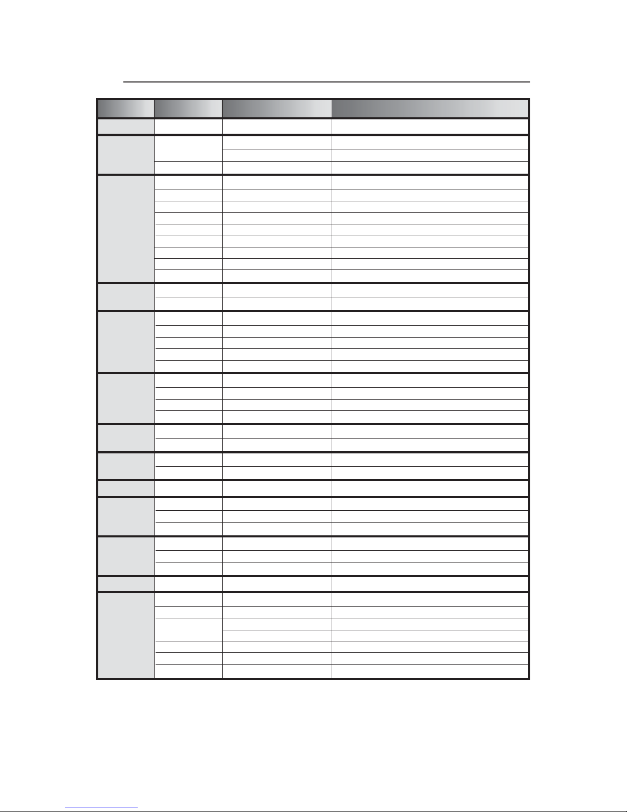
General Rules:
Refer to the Table of Section 4.1 in the following page.
By each pressure, Button MENU (E) permits to go backwards by one level.
GandH(DOWN and UP) buttons select functions and sub-functions.
Button F (ENTER) enters the function and confirms a control.
By pressing Button MENU (E) and buttons UP and DOWN (H and G) you can select the menu you have to mod-
ify.
Once the wished menu is reached, press Button F (ENTER) to confirm your selection and enter the function.
Press G or H to enter the sub-functions if available.
Always confirm your selection with ENTER.
Press MENU to go out of the function and press again to go back to the starting level.
Example: We installed our projector on the ceiling and for this reason we want the visualization of the display to
be correct.
•Press MENU
•Press H(UP) 11 times up to “MISC”
•Press ENTER the Display will show “RSET”
•Press H(UP) twice up to “DSPL”
•Press ENTER the Display will show “ONOF”
•Press H(UP) once up to “STRV”
•Press ENTER the Display will show “STND”; this is the actual configuration state.
•Press H(UP) once up to R.E.V..; the blinking point indicate the available configuration.
•Press ENTER ...... The Display visualization as been rotated to 180°.
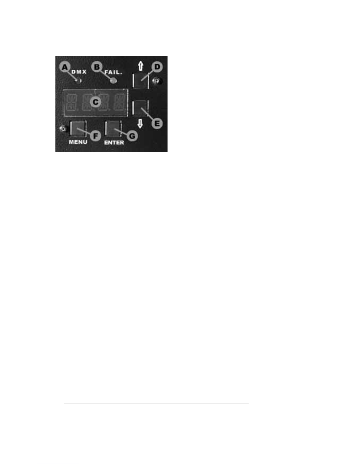
On the front panel of Performance 1200 DVP you'll find a
section for the additional functions and for setting the projec-
tor.
Following the picture, you can see all the offered possibili-
ties in detail.
All operations are to be carried out with the E,F,G,Hbut-
tons, respectively indicated as MENU,ENTER,DOWN and
UP.
The display Dwill inform you about the selected functions.
The 3 A,B, and Cleds will allow you to know:
A= reception of the DMX line.
B= lamp ON.
C= errors indicated on the ERR table.
4.0 CODIFICA E FUNZIONI SPECIALI
The indication of the display will automatically come back after 120 sec. and inform on the set starting channel
DMX.
If we are now in a sub-function, this automatic device will not assume control.

MENU FUNCTION SUB-FUNCTION DESCRIPTION
DMX (*) 1 / 505 DMX start channel
TIME
LAMP
MACH
SHOW - KH, H
RST - GO?
SHOW - KH, H
Lamp working hours (KH=thousands H=hours)
Lamp working hours reset (confirm by ENTER)
Projector working hours (KH=thousands H=hours)
ERR
EOK
E110
E220
E230
E240
E270
W310
W410
NO ERROR
EEPROM failure
Malfunction of the COLOR motor/sensor
Malfunction of the GOBOS motor/sensor
Malfunction of the GOBOS ROT. motor/sensor
Malfunction of the EFFECTS wheel motor/sensor
Cecksum setup not valid
Lamp working hours for more then 1900 hours
SHUT HOME
TEST
HOME SHUTTER
TEST SHUTTER
COL
HOME
TEST
CSHUT
MODE
ADJ
(*) OFF / ON
(*) MOD1 / MOD2
P1 / P20 -29/29
HOME COLOR
TEST COLOR
Color change in black-out position
Color switching or linear wheel motion
Fine regulation of the COLOR position (P1/P20)
GOBO
HOME
TEST
GSHUT
ADJ
(*) OFF / ON
P1 -29/29
HOME GOBOS
TEST GOBOS
GOBO change in black-out position
Fine regulation of the NEUTRAL GOBO position
RGOB HOME
TEST
HOME GOBOS rotation
TEST GOBOS rotation
EFF HOME
TEST
Esegue HOME Ruota effetti
Esegue il TEST della Ruota effetti
REFF TEST Esegue il TEST della rotazione effetti
PAN
HOME
TEST
STRV (*) STND / REV
HOME PAN movement
TEST PAN movement
Switch movement direction ( DX / SX)
TILT
HOME
TEST
STRV (*) STND / REV
HOME TILT movement
TEST TILT movement
Switch movement direction (UP / DOWN)
SCH da CH1 a CH8 1 / 8 DMX value for the indicated channel
MISC
RSET
RDMX
DSPL
SWPT
CH 8/9
VER
(*) YES / NO
(*) ON / OFF
(*) STND / REV
(*) STND / SWAP
(*)CH8/CH9
MASTER HOME (Starting RESET)
MASTER HOME via DMX control
Display on / Display off
180° rotation of the visualization display
Channel control switch PAN / TILT
Projector control (8 or 9 channels)
Show the installed software version.
(*) = default value - factory assigned
4.1 MENU, FUNCTION & SUB-FUNCTION

CH
1
2
MODE
1
2
MODE
2
SHUTTER / STROB / DIMMER
0-5 SHUTTER closed
6-100 DIMMER from channels 9 value
101-110 DIMMER 0 > 100% Automatic 6 sec.
111-120 DIMMER 100% > 0 Automatic 6 sec.
121-126 DIMMER 0 > 100% slow Fuster shut down
127-132 DIMMER 0 > 100% middle Fuster shut down
133-138 DIMMER 0 > 100% fast Fuster shut down
139-144 DIMMER 100% > 0 slow Fuster open
145-150 DIMMER 100% > 0 middle Fuster open
151-156 DIMMER 100% > 0 fast Fuster open
157-162 Dimmer 0 > 100% > 0 slow
163-168 Dimmer 0 > 100% > 0 middle
169-174 Dimmer 0 > 100% > 0 fast
175-180 Strobe lamp from 1 to 6 random [reg. 0.0-0.5 sec.]
181-186 Strobe lamp from 1 to 6 random [reg. 0.6-1.5 sec.]
187-192 Strobe lamp from 1 to 6 random [reg. 1.6-2.5 sec.]
193-250 STROB Speed adjustment
251-255 SHUTTER open
COLOR MODE 1
0 - 5 Neutral
6 - 15 Yellow
16 - 25 Blue
26 - 35 Magenta
36 - 45 Green light
46 - 55 Orange
56 - 65 Cyano
66 - 75 Pink
76 - 85 Red
86 - 95 Blu light
96 - 105 Green
106 - 115 Wood
116 - 125 White-Yellow
126 - 135 Yellow-Blue
136 - 145 Blue-Magenta
146 - 155 Green light-Orange
156 - 165 Orange-Cyano
166 - 175 Cyano-Pink
176 - 185 Red-Blue light
186 - 195 Blue light-Green
196 - 200 Random full-color (slow)
201 - 205 Random full-color (fast)
206 - 230 CW Rotation adjustment
231 - 255 CWW Rotation adjustment
COLOR MODE 2
0 - 5 Neutral
6 - 10 Yellow
11 - 15 Blue
16 - 20 Magenta
21 - 25 Green light
26 - 30 Orange
31 - 35 Cyano
36 - 40 Pink
41 - 45 Red
46 - 50 Blu light
51 - 55 Green
56 - 60 Wood
61 - 180 Positioning
181 - 185 Random fast
186 - 190 Random middle
191 - 195 Random slow
196 - 200 Random very slow
201 - 215 Random very fast
216 - 235 CW Rotation adjustment
236 - 255 CWW Rotation adjustment
SHUTTER / STROB / DIMMER
0-5 SHUTTER closed
6-100 DIMMER adjustment
101-110 DIMMER 0 > 100% Automatic 6 sec.
111-120 DIMMER 100% > 0 Automatic 6 sec.
121-126 DIMMER 0 > 100% slow Fuster shut down
127-132 DIMMER 0 > 100% middle Fuster shut down
133-138 DIMMER 0 > 100% fast Fuster shut down
139-144 DIMMER 100% > 0 slow Fuster open
145-150 DIMMER 100% > 0 middle Fuster open
151-156 DIMMER 100% > 0 fast Fuster open
157-162 Dimmer 0 > 100% > 0 slow
163-168 Dimmer 0 > 100% > 0 middle
169-174 Dimmer 0 > 100% > 0 fast
175-180 Strobe lamp from 1 to 6 random [reg. 0.0-0.5 sec.]
181-186 Strobe lamp from 1 to 6 random [reg. 0.6-1.5 sec.]
187-192 Strobe lamp from 1 to 6 random [reg. 1.6-2.5 sec.]
193-250 STROB Speed adjustment
251-255 SHUTTER open
COLOR MODE 1
0 - 5 Neutral
6 - 15 Yellow
16 - 25 Blue
26 - 35 Magenta
36 - 45 Green light
46 - 55 Orange
56 - 65 Cyano
66 - 75 Pink
76 - 85 Red
86 - 95 Blu light
96 - 105 Green
106 - 115 Wood
116 - 125 White-Yellow
126 - 135 Yellow-Blue
136 - 145 Blue-Magenta
146 - 155 Green light-Orange
156 - 165 Orange-Cyano
166 - 175 Cyano-Pink
176 - 185 Red-Blue light
186 - 195 Blue light-Green
196 - 200 Random full-color (slow)
201 - 205 Random full-color (fast)
206 - 230 CW Rotation adjustment
231 - 255 CWW Rotation adjustment
COLOR MODE 2
0 - 5 Neutral
6 - 10 Yellow
11 - 15 Blue
16 - 20 Magenta
21 - 25 Green light
26 - 30 Orange
31 - 35 Cyano
36 - 40 Pink
41 - 45 Red
46 - 50 Blu light
51 - 55 Green
56 - 60 Wood
61 - 180 Positioning
181 - 185 Random fast
186 - 190 Random middle
191 - 195 Random slow
196 - 200 Random very slow
201 - 215 Random very fast
216 - 235 CW Rotation adjustment
236 - 255 CWW Rotation adjustment
5.0 CHANNELS AND DIGITAL VALUES
8 CHANNELS 9 CHANNELS

CH
GOBOS
0 - 10 Neutral
11 - 20 GOBO 1 chann.4 controls rotation
21 - 30 GOBO 2 chann.4 controls rotation
31 - 40 GOBO 3 chann.4 controls rotation
41 - 50 GOBO 4 chann.4 controls rotation
51 - 60 Reduction
61 - 70 GOBO 5 chann.4 controls rotation
71 - 80 GOBO 6 chann.4 controls rotation
81 - 90 GOBO 7 chann.4 controls rotation
91 - 100 GOBO 8 chann.4 controls rotation
101 - 110 GOBO 1 chann.4 controls position
111 - 120 GOBO 2 chann.4 controls position
121 - 130 GOBO 3 chann.4 controls position
131 - 140 GOBO 4 chann.4 controls position
141 - 150 GOBO 5 chann.4 controls position
151 - 160 GOBO 6 chann.4 controls position
161 - 170 GOBO 7 chann.4 controls position
171 - 180 GOBO 8 chann.4 controls position
181 - 193 GOBOS Fast random
194 - 205 GOBOS Slow random
206 - 230 CW Rotation adjustment
231 - 255 CWW Rotation adjustment
GOBOS ROTATION
0 - 5 STOP
6 - 255 From 0 to 540° GOBO positioning
6 - 130 CW Rotation adjustment of the GOBO
131 - 255 CWW Rotation adjustment of the GOBO
EFFECTS
0 - 10 OPEN
11 - 90 Conversion
91 - 110 Automatic FROST from 0 to 100%
111 - 130 Automatic FROST from 100 to 0%
131 - 250 Manual FROST
251 - 255 Total FROST
PRISM ROTATION
0 - 5 STOP
6 - 130 CW Rotation
131 - 255 CCW Rotation
PAN MOVEMENT
TILT MOVEMENT
DIMMER
0 - 10 DIMMER CLOSED
11 - 250 DIMMER Adjustment
251 - 255 DIMMER OPEN
WARNING:position CHANNEL 1 at a value between 6 and
100, in order to control DIMMER with this channel.
GOBOS
0 - 10 Neutral
11 - 20 GOBO 1 chann.4 controls rotation
21 - 30 GOBO 2 chann.4 controls rotation
31 - 40 GOBO 3 chann.4 controls rotation
41 - 50 GOBO 4 chann.4 controls rotation
51 - 60 Reduction
61 - 70 GOBO 5 chann.4 controls rotation
71 - 80 GOBO 6 chann.4 controls rotation
81 - 90 GOBO 7 chann.4 controls rotation
91 - 100 GOBO 8 chann.4 controls rotation
101 - 110 GOBO 1 chann.4 controls position
111 - 120 GOBO 2 chann.4 controls position
121 - 130 GOBO 3 chann.4 controls position
131 - 140 GOBO 4 chann.4 controls position
141 - 150 GOBO 5 chann.4 controls position
151 - 160 GOBO 6 chann.4 controls position
161 - 170 GOBO 7 chann.4 controls position
171 - 180 GOBO 8 chann.4 controls position
181 - 193 GOBOS Fast random
194 - 205 GOBOS Slow random
206 - 230 CW Rotation adjustment
231 - 255 CWW Rotation adjustment
GOBOS ROTATION
0 - 5 STOP
6 - 255 From 0 to 540° GOBO positioning
6 - 130 CW Rotation adjustment of the GOBO
131 - 255 CWW Rotation adjustment of the GOBO
EFFECTS
0 - 10 OPEN
11 - 90 Conversion
91 - 110 Automatic FROST from 0 to 100%
111 - 130 Automatic FROST from 100 to 0%
131 - 250 Manual FROST
251 - 255 Total FROST
PRISM ROTATION
0 - 5 STOP
6 - 130 CW Rotation
131 - 255 CCW Rotation
PAN MOVEMENT
TILT MOVEMENT
8 CHANNELS 9 CHANNELS
3
4
5
6
7
8
9
SPECIAL ACTION
When RDMX function have been activated in the configuration menu, it’s possible, by a combination of tha channels values , to
allow the projector MASTER RESET.
MASTER RESET:
CHANNEL 1 = Value 0
CHANNEL 2 e CHANNEL 3 = Value0>255>0

6.0 FOCUS ADJUSTMENT
In order to adjust the objective, it is necessry to pre-set channels
so that the shutter is open; assign the white colour and insert the se-
lected gobo.
Rotate the knob on the front part of the projector which is hi-
ghlighted by the writing FOCUS (see the picture) and adjust the fo-
cusing device of the objective, positioning the projector wherever
you wish.
WARNING: switch off the projector before operating
Ope the cover of the Performance 1200 DVP first.
The gobo-wheel contains both steel gobos and dichroic gobos. They are interchangeable simply by removing
the little elastic ring with a screwdriver (see figure).
In order to replace a dichroic gobo with a steel gobo, put a thick ring between the gobo and the elastic ring (see
part. B).
Insert the chosen gobo and place again the steel ring, paying attention that it reaches its correct position.
7.0 GOBOS REPLACEMENT

8.0 ORDINARY MAINTENANCE
Ordinary maintenance on the projectors PERFORMANCE 1200 DVP is
necessary to maintain the perfect efficiency of the unit and to avoid defects
like the low luminosity of the light beam, irregular motion of the mirror or ot-
her rotating components. In the fi-
gures you can see those
components that can easily accu-
mulate dust and grease. Clean
them using a soft cloth and com-
mon glass-cleaners. As regard
the picture on side, the intervention must be effected by a mechanical
maintenance operator, who will clean the anti-heat filter, reachable only
from the inside of the projector.
8.1 EXTRAORDINARY MAINTENANCE
To make an extraordinary maintenance, it is necessary the presence of a generic or quali-
fied mechanical operator, according to the type of the needed intervention. To make an ex-
traordinary maintenance, it is necessary the presence of a generic or qualified mechanical
operator, according to the type of the needed intervention. To make it simple, we advice to
completely extract the mechanical part of the PERFORMANCE 1200 DVP from its box : look
figure where you can see the 4 hexagonal screws (A); the 2 focus bracket screws that have to
removed, so that you can extract the whole mechanical part, supporting the motors and the
various wheels ( effects, color, gobos). In this way it will be much more easy to observe the
components to maintain and/or replace. In the following figures it’s possible to observe the dif-
ferent particulars that have to be cleaned and, at the same time, the whole mechanical struc-
You must particularly take care of the sensors which are really fundamental in the unit working.
The sensors are absolutely necessary when a general reset of the projector is needed. If this function is not cor-
rectly executed, it will totally compromise the regular working of the projector, at least for the group referred to the
sensor itself. Es : when there’s an irregular reset of the color wheel, all the setted colors will not correspond to the co-
lours listed in the chapter about DMX digital values.
The same situation will occur in the case of the gobos wheel or the effects wheel.
The section shutter/strobo/dimmer doesn’t use sensors during the reset
positioning but it’s conditioned by a mechanical beat of the shutter shovels.
You must carefully clean also the moving zoom lens. After several wor-
king hours dust and grease will be stored on this lens, carried inside the
projector by the cooling fans.

8.2 ELECTRONIC MAINTENANCE
This section is dedicated in detail to the electronic connections between the card and the mechanical compo-
nents, assembled in the projector. These informations will be absolutely necessary when the mechanical unit has to
be removed from the projector for maintenance and/or repair.
The connections are made using handy connectors and are detailed in fig. 18 where you can find indications
about the connection between a specific connector and a specific component of the mechanical unit. This includes
the motors and the sensors of the various effects wheels ( color, gobos, prisms, shutter etc.).
WARNING! An improper use of this documentation made by not specifically qualified staff can damage irreme-
diably the electronic and/or mechanical components of the projector.
1GOBOS rotation motor
2 COLOR wheel motor
3 GOBOS wheel motor
4 SHUTTER motor 1
5 SHUTTER motor 2
6 EFFECTS wheel motor
7 EFFECTS rotation motor
8 PAN movement motor
9 TILT movement motor
10 COLOR wheel sensor
11 GOBOS wheel sensor
12 GOBOS rotation sensor
13 EFFECTS wheel sensor
14 DMX in/out

9.0 TROUBLESHOOTING
PROBLEM CAUSE ACTION
The projector doesn’t swich on
The projector swiches on but
doesn’t answer to commands
Defecting projection
Projection with halo
The color or other effects
doesn’t coincide to the selected
value.
The PAN or TILT movement
doesn’t coincide to the selcted
value
- The power supply is not present
- The lamp is not working
- Wrong DMX configuration
- Defective cables
- Defective control unit
- The lens is broken
- Dust or grease stored on the all
parts of projector
- Dust or grease stored on the all
parts of projector
- Position sensor dirty with dust or
grease
- Cinghia rotta
- Defective motor
- Electronic board
- Defective motor
- Electronic board
Check if the luminous indicator is lighted
or not.
Replace the lamp.
Make sure that the projector is correctly
configurated.
Replace or repair the DMX cable.
Check the control unit by means of other
working projectors.
Technical aid is required.
Check that the lens are not broken.
Remove dust or grease stored on lenses.
Carefully clean the optical group lenses
and the projector components (see “Main-
tenance” chapter).
Carefully clean the optical group lenses
and the projector components (see “Main-
tenance” chapter).
Technical aid is required.
Carefully clean the optical group lenses
and the projector components (see “Main-
tenance” chapter).
Technical aid is required.

•Lamp HMI 1200 W - 750 hours life - socket sfc 15,5-6
•6 metal and 2 dichroic rotating gobosall interchangeable and indexable position on 540°
•Set of 10 extra metal gobos, given with the projector
•1 diameter projection reducer
•10 basic colors + white + 7 bi-colors
•2 color conversion filters superimposing to the basic colors for a total of 36 colors + bi-colors
•Rainbow effect
•Blacklite filter
•2 rotating prisms : 3 facet and infinity
•Dimmer from 0 to 100%
•Adjustable strobe
•Adjustable focus
•Multifunctional display
•Remote reset via DMX; selectable from display
•Software Upgrade via DMX (with UNI-PROG 8 accessory)
•Internal self-test with led indicator
•Internal power factor correction
•DMX 512 Standard
•8/9 control channels
PERFORMANCE 1200 DVP Code: 02A018
11.0 TECHNICAL NOTES
10.0 DECLARATION OF CE CONFORMITY
DECLARATION OF CE CONFORMITY
We, Manufacturer/Importer
COEF srl.
Via Albinatico, 80-82
51019 Ponte Buggianese (Pistoia)
ITALY
Declare that the product
Performance 1200 DVP
is in conformity with
In accordance with 89/336 EEC-EMC Directive and
With the actual required safety standards in accordance with LVD 73/23 EEC
Name: Alfonso Ceccarelli
Position: Managing Director
Signature:
Date: Ponte Buggianese, 27 Febbraio 2001

12.0 ELECTRIC DIAGRAM
FAN
PFC Capacitors
LAMP
TO ELECTRONIC BOARD
TR1
TR2
POWER
SWITCH
AC IN IGNITER
Filter
THERMAL
SWITCH
L
T
COVER
SWITCH
Performance 1200 DVP

13.0 DIMENSIONS
LIST OF PARTS
1 - Lock Knobs
2 - Mains power soket
3 - Mains switch
4 - DMX IN
5 - DMX OUT
7 - Handspike
8 - Objective
9 - Focus adjustment

14.0 PART ASSEMBLY

Table of contents
Other COEF Lighting Equipment manuals

COEF
COEF MP 150 SPOT DV User manual

COEF
COEF EMULATION CTC User manual

COEF
COEF MASTERSHOW 512 User manual

COEF
COEF PERFORMANCE 250DV DVP User manual

COEF
COEF Sirio RAY 1200 02B014 User manual

COEF
COEF EMULATION STROBE User manual

COEF
COEF Sirio 1800DV User manual

COEF
COEF EMULATION WRGB User manual

COEF
COEF MP 700 ZOOM User manual

COEF
COEF MP 700 WASH User manual
Popular Lighting Equipment manuals by other brands

Hubbel
Hubbel KIM LIGHTING LIGHTVAULT LTV50 Series installation instructions

PacLights
PacLights FCPC Series installation guide

Briloner
Briloner MAL 2267-150P Mounting instructions

American DJ
American DJ DJ SCAN User instructions

Tomar
Tomar Spider Microbar instruction manual

Tranberg
Tranberg TEF 2940 user manual