COEF MP 150 SPOT DV User manual

Revision 2.
http://www.coef.it
e-mail:[email protected]
150
1
5
0
s
p
o
t
Code ZL-013001-01
OPERATING INSTRUCTIONS
Revision 2.0

Pag.1
SUMMARY
DECLARATION OF CE CONFORMITY................................................................................ 2
ADVICES FOR A CORRECT INSTALLATION...................................................................... 2
GENERAL WARRANTY CONDITIONS............................................................................... 3
PACKING CONTENTS ..................................................................................................... 3
1.0 DIMENSIONS & POSITIONING................................................................................. 4
2.0 TECHNICAL NOTES .................................................................................................. 4
3.0 INSTALLATION ........................................................................................................ 5
3.1 LAMP MOUNTING OR REPLACING ............................................................................ 5
3.2 PROJECTOR INSTALLATION..................................................................................... 6
4.0 POWER SUPPLY CONNECTION ................................................................................. 7
4.1 DMX 512 CONNECTIONS .......................................................................................... 7
5.0 SPECIAL FUNCTIONS AND PROJECTOR ASSIGNMENT............................................... 8
6.0 MENU, FUNCTION & SUB-FUNCTIONS ...................................................................... 9
7.0 CHANNELS AND DIGITAL VALUES .......................................................................... 10
7.1 SPECIAL ACTION ................................................................................................... 11
7.2 AUTONOMOUS OPERATION.................................................................................... 11
8.0 LAMP ADJUSTMENT ............................................................................................... 12
9.0 ORDINARY MAINTENANCE..................................................................................... 12
9.1 EXTRAORDINARY MAINTENANCE........................................................................... 12
9.2 ELETTRONIC MAINTENANCE .................................................................................. 14
10.0 TROUBLESHOOTING ............................................................................................ 15
11.0 WIRING DIAGRAMS............................................................................................. 16

Pag.2
Declaration of CE conformity
We Manufacturer IAG Room 2310-2311, Press Building, No 2 Shennan Zhong Road, Shenzhen, China, 518027
Declare that the product MP150 Spot DV is in conformity with 89/336 EEC-EMC directive and with the actual
required safety standars in accordance with LVD 73/23 EEC
Shenzhen, 01 October 2005
ATTENTION: carefully read the directions of this manual. Exclusively follow the safety rules in force and do not carry out assembly and/or
maintenance operations without taking all precautions as indicated in the different sections or without the necessary specialization.
This manual must always accompany the equipment, therefore it must be available and readable at any moment if necessary. Also in
case of sale, rent, change of place and/or ownership, these documents shall be enclosed with the relative equipment.
ADVICES FOR A CORRECT INSTALLATION
This equipment is destined to an exclusively Professional use.
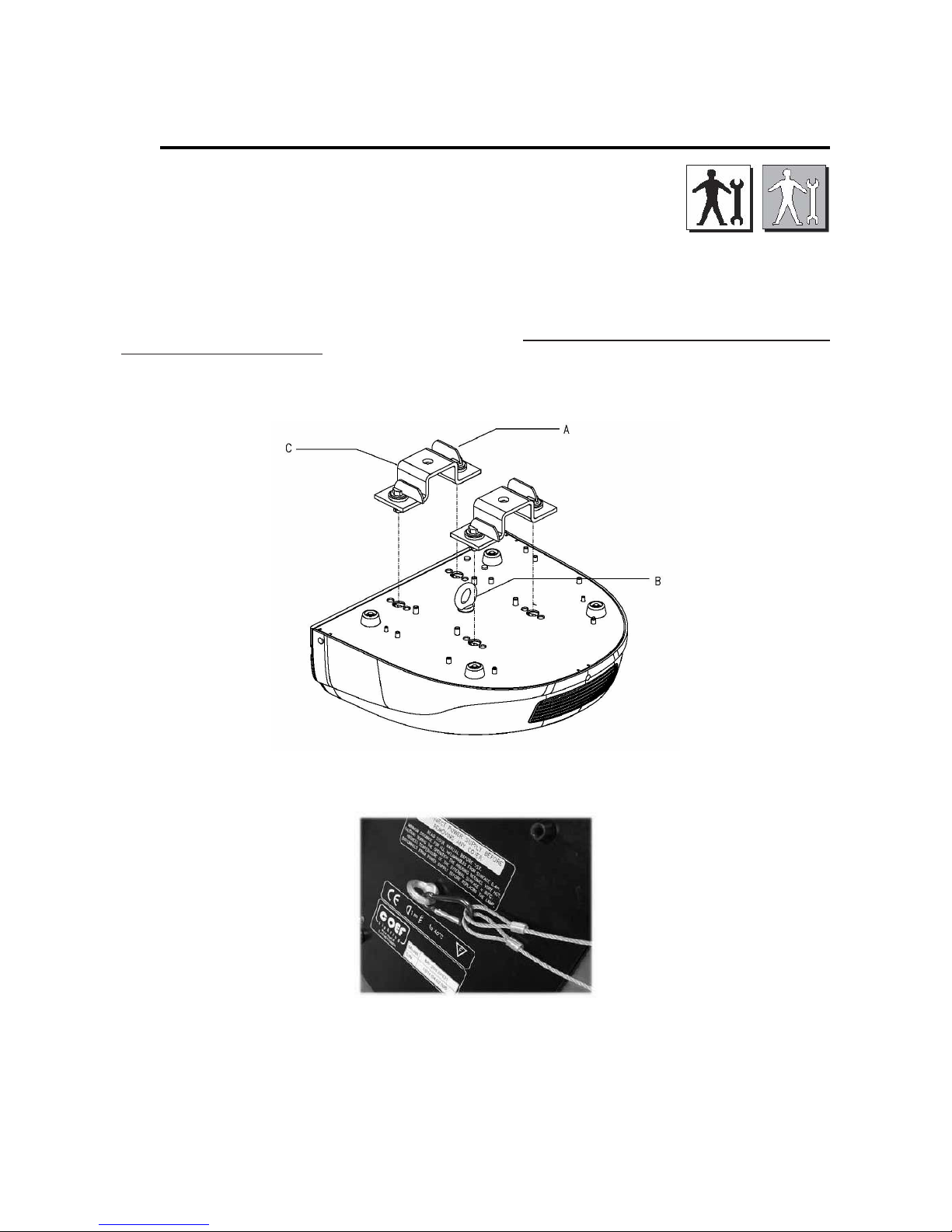
1) Make sure that all the fastening parts of the spotlight are in good condition. Regulate the proportions of the fastening accessories
(screws, bushes, nuts, supports, etc.) in order to be slightly over-dimensioned as compared to the actual requirements.
2) Carefully check the contents of the packaging and the completeness of the components. If any of the parts listed hereunder is missing,
please contact your Dealer immediately.
3) Do not install the projector outside where the influence of atmospheric factors could damage the unit working (rain, wind, intense heat
etc.) or indoor if there is a high percentage of humidity.
4) Do not clean the projector using water jets or immersion in different liquids. Scrupulously follow the indications given in the chapter
MAINTENANCE.
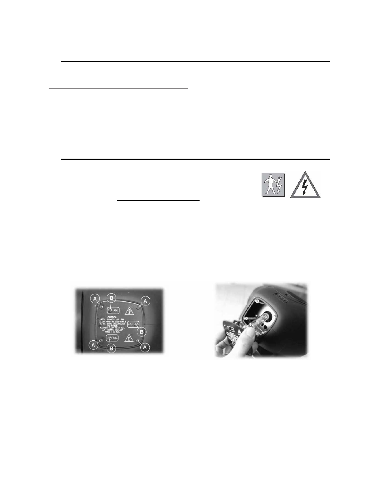
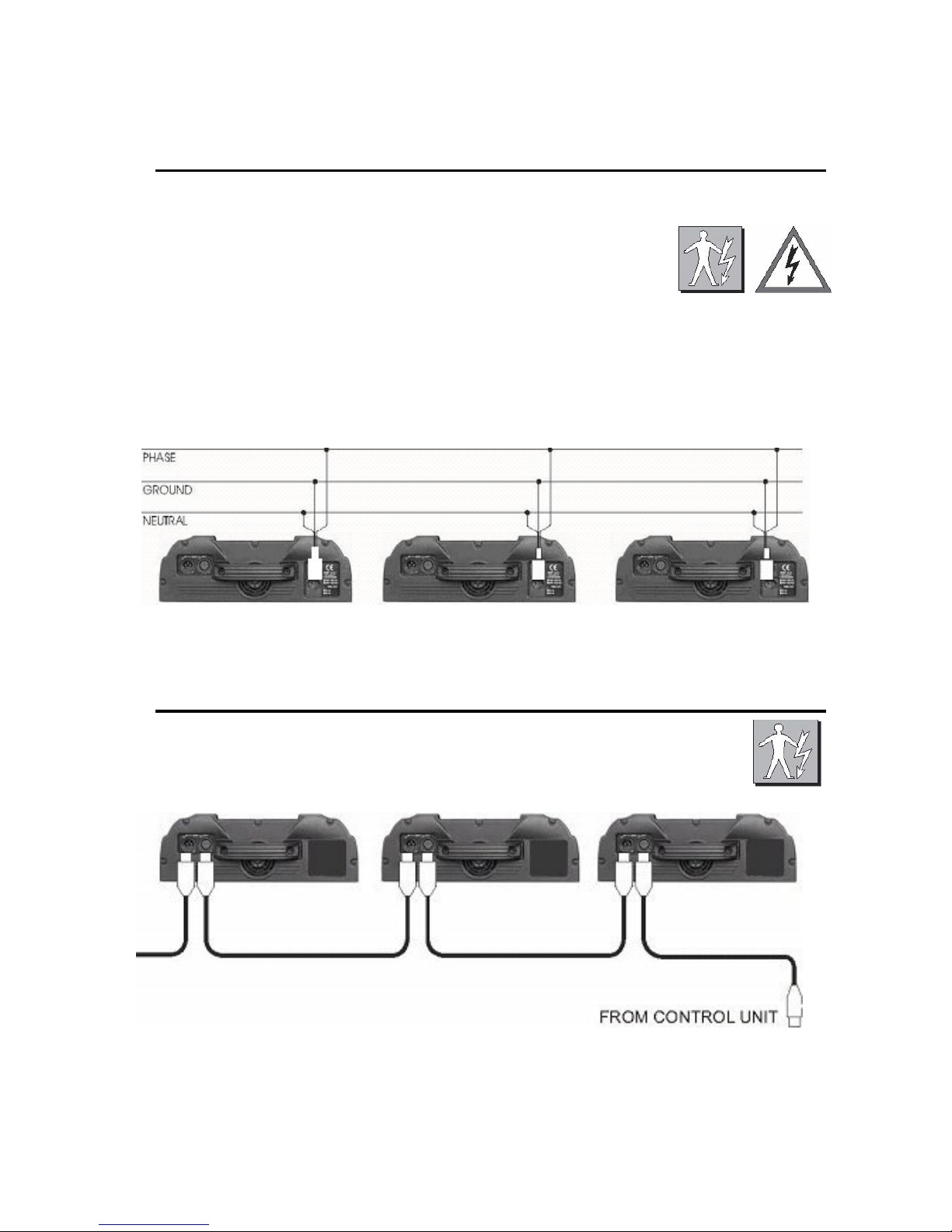
5) Make the electric connections and the installation / replacement of the lamp after having disconnected the power supply and after haved
positioned the power switch to OFF.The apparatus is classified as belonging to Class 1 type of protection against electric shocks. Its
connection to an earthed mains unit is compulsory. The equipment must be protect by an adeguated magneto-thermal switch. You are
recommended to equip the system with aptly dimensioned differential switches.
6) Do not touch in any case the internal and external parts of the projector without previous authorization of the constructor and make
modifications only by the intervention of qualified staff.
7) Make sure that the projector is correctly fixed on the support as indicated in par. 3.3
8) If the bulb explodes, the particular design of the apparatus prevents the splinters from going outside the projector. All the parts, therefore,
shall be complete and perfectly assembled. The lenses, if visibly damaged, shall be replaced by original spare parts.
9) Minimum distance from illuminated objects: The projector must be positioned in such a way that objects struck by the light beam are
located at least 1 metres from the projector objective.
10) Minimum distance from inflammable materials: 0.4 meters
11) MAX ambient temperature: 40° C.
12) MAX external surface temperature:80° C.
13) Don’t look directly the lamp trough the lens.
14) We recommend not to look at the lamp without wearing a proper protection; also ensure that the covers are assembled to
the equipment.
15) Inside the equipment there are high temperatures and tension/current values which might be very dangerous. It is necessary to
disconnect the equipment from the mains before removing its protection covers and wait for 30 minutes at least before touching any part
inside.
16) Do not switch on the equipment if its lamp is not inserted.
17) Leave sockets and air outlets free from encumbrances and clean them periodically (see “Maintenance” section).
18) Do not leave the packaging elements (polystyrene, nylon, metal parts, etc.) unattended; they might be dangerous for children.

Pag.3
This manual has been organized in order support the user, the installer or the maintenance operator of the described unit with those necessary
informations for a correct use of the installation and working procedures of the same unit.The various procedures will be just signalled by indicators
(when necessary) evidencing the operation dangers and the necessity of technical support.
Please find here below a list of symbols and relative meaning.
OPERATOR :Not particulary qualified staff, that can operate when no specific knowledge is required
COEF OPERATOR:Technical staff, qualified and trained by the constructor, for repair and extraordinary operations.
MECHANICAL OPERATORS: Staff employed in the ordinary mechanical maintenance.
SPECIALIZED MECHANICAL OPERATOR:Qualified staff employed in extraordinary authorized installations and
repair.
ELECTRIC OPERATORS:Staff employed in the ordinary electric maintenance.
SPECIALIZED ELECTRIC OPERATORS: Qualified staff employed in extraordinary authorized installations and repairs.
DANGER SIGNAL: Generic dager signal and electric shock danger signal.
GENERAL WARRANTY CONDITIONS
• The guarantee is valid for a period of 12 months from the date of purchase of the equipment.
• The guarantee is not valid in case a wrong voltage or frequency is selected.
• The parts which are proved to have manufacturing defects are also covered by the guarantee.
• The external parts of the equipment, its removable elements and lamps are excluded from the guarantee; for these parts we recommend
to follow the directions supplied by their manufacturers.
• The guarantee is not valid in case of tampering or repairs carried out by non-authorized personnel.
• The replacement of the equipment during the validity of the guarantee is not provided for.
• The transport freights from and to the manufacturer for repairs under guarantee are at Customer’s charge.
• When applying for the repair, always mention the serial number and the model of the equipment.
PACKING CONTENTS
Carefully check the contents of the packaging and the completeness of the components. If any
of the parts listed hereunder is missing, please contact your Dealer immediately:
• Complet MP150 Spot DV unit
• This user manual
• 1 cable with 1 XLR 3 pin male and 1 XLR 3 pin female
• 1 AC Power cord
• 1 safety-chain equipped with two snaps.
• 1 complete bracket for the ceiling fixing
• 1 bee M10
PROTECT NATURE.
DO NOT DISPOSE OF THE PACKAGING IN THE ENVIRONMENT.
CAREFULLY KEEP THE BOX AND THE COMPONENTS OF THE PACKAGING FOR ANY DISPLACEMENT
OR RE-SHIPMENT OF THE EQUIPMENT.
Do not leave the packaging elements (polystyrene, nylon, metal parts, etc.) unattended; they might be
dangerous for children.

Pag.4
1.0 DIMENSIONS & POSITIONING
It is possible to set up the MP150 Spot DV in any position.
2.0 TECHNICAL NOTES
MP150 Spot DV Code: ZL-013001-01
• Lamp: HSD 150/70 -12.000 lumen
• 16 bit movement resolution -PAN 540° / TILT 270°with automatic repositioning
• Optical system with 3 lenses + dichroic reflector
• 11 colors + white + bi-colors
• 5 rotating metal gobos all interchangeable+2dichroic gobo
• Adjustable strobe
• Rainbow effect adjustable in speed
• Focus adjustable
• Black light filter
• Shutter motorized
• Multifunction display
• Remote reset via DMX
• Remote On/Off lamp via DMX
• Software upgrade via DMX (with UNI-PROG 8 Accessory)
• Automatic fault survey
• Internal power factor correction
• DMX 512 standard
• Weight:13Kg
Power supply | Absorbed power
Volts Hz I W
230V~ 50Hz 0,9A. 210W

Pag.5
3.0 INSTALLATION
The constructor is not be considered responsible in case of:
• Improper use of the unit or use by not trained staff
• Use in contrast with the directions on work safety
• Wrong installation
• Defective power supply
• Serious lacks in the necessary maintenance
• Unauthorized modifications and interventions
• Use of spare parts that are not original or not specific for the unit
• Total or partial inobservance of instructions
• Unusual events
3.1 LAMP MOUNTING OR REPLACING
WARNING: read carefully
• Switch off the projector before operating.
• The lamp used in the fixture is a high pressure lamp and must be handled very carefully.
• The unit is realized to use only HSD 150/70 or compatible lamps; absolutely don’t use other types of lamp.
• The lamp must be changed if damaged or deformed by heat.
• Wait at least 15 minutes after the projector has been switched off before operating again, in order to let it cool down
and avoid the lamp explosion.
• Wear protection gloves and glasses.
• Read carefully the lamp builder’s instructions.
• Don’t look directly the lamp.
Wait 30 minutes in order to avoid burns.
Unscrew with a cross screwdriver the 4 screw A and to remove the cover that supports the lampholder. Insert delicately the lamp in the
projector support, driving it with the cover. Pay attention: the lampholder’s wires must correctly reenter in the projector. Block the cover
screwing the screws up ( part. A).

Pag.6
3.2 PROJECTOR INSTALLATION
To fix the MP150 Spot DV is necessary, when the installation has to be on a raised-from-the ground
support, to block the quick lock/release brackets of the unit by means of a screw provided with nut and
locknut measuring not less than M10X50, to insert in the central pre-arranged hole on the fixing
bracket. In addiction to the provided quick lock/release (omega) brackets, in order to guarantee a
necessary security and in respect of the actual safetyrules concerning the projectors’ installation, it is compulsory to install a safety-
chain, equipped with two snaps, provided with the projector, to connect the MP150 Spot DV 's body to the fixing structure.
ATTENTION: the safety chain, equipped with two snaps which can be hooked to the two pivots placed under the base of the MP150
Spot Dv, (see part. B), must be properly installed and fixed to the supporting structure, in a way that an incidental givin in of the
main bracket would leed to the shortest possible fall of the projector. After such an intervention the safetychain must be
replaced with another original part.
ATTENTION: COEF is not responsible for installations not correctly made or made without respecting the above
indications: those installations are considered dangerous.

Pag.7
4.0 POWER SUPPLY CONNECTION
WARNING: In order to guarantee the utmost safety, connect the apparatus only to a properly earthed mains system.
The projector is designed to work at the tension and frequency indicated by the electrical data label on the rear. Before
connecting the projector to the mains, a qualified electrician must check its conformity.
• The projector must be protect by an adeguated magneto-thermal switch .
• Don't power the unit with a dimmer circuit.
Power : indicated in the the serigraphy table (tollerance: +5% / -10%)
Should there be different electrical characteristics or special steps to be carried out, please contact COEF by telephone or e-mail.
Supply the projector by connecting it as indicated in picture.
Connect the projector and the control unit to a wire in conformity with the EIA RS-485 standards: braided
bipolar, shielded, 120 ohm of characteristic impedance, 22-24 AWG, equipped with Cannon 3 Pin XRL plugs.
Respect the DMX 512 signal input and output according to the panel indications. A terminal pin with 120 ohm
resistance (¼ Watt minimum) must be inserted between the terminals 2 and 3 in the last piece of apparatus.

Pag.8
5.0 SPECIAL FUNCTIONS AND PROJECTOR ASSIGNMENT
On the front panel of MP150 Spot DV you'll find a section for the additional
functions and for setting the projector. Following the picture, you can see all
the offered possibilities in detail. All operations are to be carried out with the
A, B, C, D.
The display E will inform you about the selected functions.
The 3 leds will allow you to know:
DMX = reception of the DMX line.
LAMP = lamp ON.
FAIL = errors indicated on the ERR table (see table 6.0).
On switching the projector on, the display will indicate the type of projector and the version of control software which have been
installed. To this purpose, please remember that this type of projector belongs to a new generation of projectors, designed with the
possibility of updating the software version through the normal DMX connection by means of a programmer deliberately created:
UNI-PROG 8.
After the indication MSTR HOME, the projector carries out the RESET and gets ready to be controlled from the connected
console.
The display will indicate 1 as default value. This means that the first channel occupied by the projector will respond to the values
sent to channel 1 by the DMX line. This enables us to make MP150 Spot DV (which we are installing) completely independent from
control or integral with any other installed projector.
General Rules:
Refer to the Table of Section 6.0 in the following page.
By each pressure, Button MENU (A) permits to go backwards by one level.
Dand C(DOWN and UP) buttons select functions and sub-functions.
Button B (ENTER) enters the function and confirms a control.
By pressing Button MENU (A) and buttons UP and DOWN (C and D) you can select the menu you have to modify. Once the
wished menu is reached, press Button B (ENTER) to confirm your selection and enter the function. Press C or D to enter the
sub-functions if available.
Always confirm your selection with ENTER.
Press MENU to go out of the function and press again to go back to the starting level.
Example: We installed our projector on the ceiling and for this reason we want the visualization of the display to be correct.
Press B MENU
Press C (UP) 12 times up to “MISC”
Press ENTER the Display will show “RSET”
Press C (UP) twiceupto“DSPL”
Press ENTER the Display will show “ONOF”
Press C (UP) once up to “STRV”
Press ENTER the Display will show “STND”; this is the actual configuration state.
Press C (UP) once up to R.E.V..; the blinking point indicate the available configuration.
Press ENTER ...... The Display visualization as been rotated to 180°.
Press MENU 3 times to return to starting MENU.
The indication of the display will automatically come back after 120 sec. and inform on the set starting channel DMX.
If we are now in a sub-function, this automatic device will not assume control.

Pag.9
6.0 MENU, FUNCTION & SUB-FUNCTIONS (*) = default value -factory assigned
DMX (*)1/504 O (*) 1/505 DMX start channel
SHOW KH,H Lamp working hours (KH = thousand H = hours)
RST GO? Lamp working hours reset (confirm by ENTER)
MACH SHOW KH,H
E OK No error
E110 EEPROM failure
E220 Malfunction of the COLOR motor/sensor
E230 Malfunction of the GOBOS motor/sensor
E240 Malfunction of the ROTATION GOBOS motor/sensor
E250 Malfunction of the PAN motor/sensor
E260 Malfunction of the TILT motor/sensor
E510 Malfunction encoder PAN
E520 Malfunction encoder TILT
W310 Checksum Setup not valid
W410 Lamp working hours for more than 500 hours
HOME HOME SHUTTER
TEST TEST SHUTTER
ADJ P1 -10/10 Fine regolation of the closing shutter
HOME HOME COLOR
TEST TEST COLOR
CSHUT (*) OFF/ ON Color change in black-out position
ADJ P1/ P20 -29/29 Fine regolation of the COLOR position (P1/P20)
HOME HOME GOBOS
TEST TEST GOBOS
GSHUT (*) OFF/ ON Gobos change in black-out position
ADJ P1 -29/29 Fine regolation of the NEUTRAL GOBO position
HOME HOME ROTATION GOBOS
TEST TEST Rotation GOBOS
HOME HOME PAN
TEST TEST PAN
STRV (*) STDN / REV Switch movements direction (DX / SX)
ENCO (*) ON / OFF ON/OFF the automatic repositioning of the PAN
HOME HOME TILT
TEST TEST TILT
STRV (*) STDN / REV Switch movements direction (UP / DOWN)
ENCO (*) ON / OFF ON/OFF the automatic repositioning of the TILT
RUN (*)OFF/PR1/PR2/PR3/PR4 Automatic operation with 4 different programs
MIC (*) OFF / ON Automatic microphone start programs
MICL 0 / 99 (*) 80 Gain microphone regulation
MICF 1 / 9 (*) 8 Frequency regulation ( 1 = low 9 = high)
MSTR (*) OFF / ON Master -slave function
SCH CH1 / CH9 DMX value for the indicate channel
ONOF (*) ON / OFF / AUTO Lamp ON / OFF / Lamp Off after 1 hours of no DMX change
CDMX (*) NO / YES Lamp switching on bu DMX control
RSET MASTER HOME (Starting RESET)
RDMX (*) YES / NO MASTER HOME via DMX control
(*) ON / OFF Display On / Display OFF
(*) STND / REV 180° rotation of the visualitation display
SWPT (*) STND / SWAP Channel control switch PAN / TILT
CH8/9 (*) CH8 / CH9 Projector channel control 8 / 9 channels
VER Show the installed software version
TILT
SELF
LAMP
DSPL
MISC
COLOR
GOBO
RGOB
PAN
LAMP
TIME
ERR
SHUT

Pag.10
7.0 CHANNELS AND DIGITAL VALUES
0-5
6-20
CHANNEL DMX VALUE FUNCTION
SHUTTER-STROBO
21-40
41-60
61-250
251-255
0-5
6-15
16-25
26-35
36-45
46-55
56-65
66-75
76-85
86-95
96-105
106-115
116-125
126-135
136-145
146-155
156-165
166-175
176-185
186-195
196-200
201-205
206-225
226-245
246-255
COLORS
GOBOS
GOBOS ROTATION
0-10
11-23
24-36
37-49
50-61
62-74
75-87
88-100
101-113
114-126
127-139
140-151
152-164
165-177
178-190
191-198
199-205
206-230
231-255
0-5
6-130
131-255
6-255
PAN MOVEMENT
PAN MOVEMENTFINE ADJUSTMENT
TILT MOVEMENT
TILT MOVEMENTFINE ADJUSTMENT
MOVEMENTS TIME ADJUSTMENT (For use this channelset CH8/9 to 9channels)
0-5
6-250
251-255
NO DELAY
ADJUSTMENT DELAY
MAX DELAY
SHUTTER CLOSED
FLASH RANDOM FAST
FLASH RANDOM MEDIUM
FLASH RANDOM SLOW
STROBE SPEEDADJUSTMENT
SHUTTER OPEN
NEUTRAL
YELLOW
BLUE
MAGENTA
GREEN LIGHT
ORANGE
CYANO
PINK
RED
BLUE LIGHT
GREEN
WOOD
WHITE-YELLOW
YELLOW-BLUE
BLUE-MAGENTA
GREEN LIGHT-ORANGE
ORANGE-CYANO
CYANO-PINK
RED-BLUE LIGHT
BLUE LIGHT-GREEN
RANDOM FULL-COLOR(fast)
RANDOM FULL-COLOR(slow)
CW ROTATION ADJUSTMENT
CCW ROTATIC
RAINBOW EFFECT
NEUTRAL
GOBO1 Channel 4 control rotation
GOBO2
GOBO3
GOBO4
GOBO5
GOBO6
GOBO7
GOBO1
GOBO2
GOBO3
GOBO4
GOBO5
GOBO6
GOBO7
GOBOS
GOBOS
CCW
CW
Channel 4 control rotation
Random FAST
Random SLOW
Rotation Adjustment
Rotation Adjustment
STOP
CW
CCW
GOBO Position
Rotation speed adjustment ofthe gobo (if thevalue of the channel3 is from 11 to 100)
Rotation speed adjustment ofthe gobo (if thevalue of the channel3 is from 101to 190)
1
2
3
4
5
6
7
8
9

Pag.11
7.1 SPECIAL ACTION
When the lamp control via DMX (CDMX) and the reset via DMX (RDMX) function have been activated in the configuration menu,
it’s possible, by a combination of the channels values, to control the lamp switch ON/OFF or to allow the projector MASTER RESET.
Lamp ON via DMX:
CHANNEL 2 = value 0
CHANNEL 3 and CHANNEL4=value0>255>0
Lamp OFF via DMX:
CHANNEL 2 = value 255
CHANNEL 3 and CHANNEL4=value0>255>0
MASTER RESET via DMX:
CHANNEL 1 = value 0
CHANNEL 2 and CHANNEL3=value0>255>0
7.2 AUTONOMOUS OPERATION
The Mp 150 Spot DV has a particularity that marks it from most of similar product: the possibility of an entirely autonomous
operation, free from connection to any control unit.
This feature allows the projector, or the projectors connected between them, to perform 4 different programs pre-planned
selectable easily across the control panel of the projector (you see paragraph MENU -FUNCTIONS and SUB-FUNCTION section
“SELF”). To the feature of operation of complete autonomy there is another support of it determined interesting and it is the
possibility to assign a projector, deputy part of a group of projectors (until a maxim of 10) connected together through a dmx cable,
like MASTER and therefore total controller of the other connected as SLAVE. The program chosen will be therefore performed in
perfect synchrony from all the projectors connected to fall down.
The 4 programs include two different typologies of planning and the same two further typologies, can be performed in fast or
slow manner. For clarity please see the table:
PROGRAM 1 arranged for an involvement to 360° of the area of projection and with Fast feature of operation
PROGRAM 2 arranged for an involvement to 180° of the area of projection and with Fast feature of operation
PROGRAM 3 arranged for an involvement to 360° of the area of projection and with Slow feature of operation
PROGRAM 4 arranged for an involvement to 180° of the area of projection and with slow feature of operation
Every program is composed from 64 scene and the change of scene can be planned either automatic (value of default) either
made conditional from the musical impulses received from the inside microphone of the projector. In such microphone is adjustable
either the sensibility and the frequency of calculation of the number of beat (BIT) before the change of scene; this regulation takes
on values from 1 (high frequency BIT) to 9 (low frequency BIT).
To perform the automatic programs proceed as follows:
a) choose the MENU “SELF” on the display
b) establish if the projector should take the function of MASTER or SLAVE with the sub-function “MSTR”
c) establish if the control of the scene stage should be driven from the microphone or in automatic manner across the sub-
function “MIC”
d) choose the program, in base to the table above restored with the sub-function “RUN” and then confirm with ENTER
ATTENTION! All the projectors, both MASTER that SLAVE, must be assigns with DMX value=1

Pag.12
8.0 LAMP ADJUSTMENT
• Don’t look directly the beam trough the lens.
•
The lamp is pre-regulated by the factory. Only fine-adjustment.
Don’t move the screws ”B” up to upper or lower extremities.
Lamp adjustment is necessary to obtain a uniform and powerful light beam. Switch
on the projector and set the channels without gobo and colors. Adjust the three
screws B until you reach the ideal condition between power and homogeneity.
9.0 ORDINARY MAINTENANCE
Ordinary maintenance on the projectors MP150 Spot DV is necessary to maintain the perfect efficiency of the
unit and to avoid defects like the low luminosity of the light beam or the elevated overheating of the equipment.
In the figures you can see those components that can easily accumulate dust and grease. Clean them using a
soft cloth and common glass-cleaners.
9.1 EXTRAORDINARY MAINTENANCE

Pag.13
After had access to the inside part of the projector ( unscrew the 5 Screw (A) to take out
the cover of the base to enter the sensors of the PAN movement ) special caution will be
dedicated to the sensors that put on a fundamental role in the operation of the equipment.
The sensors are indispensable in the moment of the general reset of the projector, function
that if not perform correctly, harms in total manner the normal operation of the projector, at
least for what pertains the group associated to the sensor.
Maintain clean also all the openings that allow the convey of the flows of air destined to
the ventilation forced. The Fan are in general a catalysts for dust and fat and when these
deposit themselves on the pale of the same fan, the values and the essential features
change themselves and compromise the good operation of the component destined to the
cooling.
For the access to the parts of the arm (particularly are present the sensors dedicated to the TILT movement ) unscrew the
lives (B) and dismiss the cover in plastic of the arm.
The sensors of the relevant encoder of the PAN and TILT movements are located respectively in the base and in the arm of the
MP150 Spot DV. The images illustrate clear these components and where to intervene with precision for the intervention of
maintenance.

Pag.14
WARNING: switch off the projector before operating.
9.2 ELETTRONIC MAINTENANCE
This section is dedicated in detail to the electronic connections between the card and the mechanical components, assembled in the
projector.These information will be absolutely necessary when the mechanical unit has to be removed from the projector for
maintenance and/or repair.
The connections are made using handy connectors and are detailed in figure where you can find indications about the
connection between a specific connector and a specific component of the mechanical unit. This includes the motors and the sensors
of the various effects wheels ( color, gobos, prisms, shutter etc.).
WARNING! An improper use of this documentation made by not specifically qualified staff can damage irremediably the
electronic and/or mechanical components of the projector.
1 Motor SHUTTER / STROBE 11 DMX in
2 Motor COLOR 12 Sensor TILT
3 Motor GOBOS 13 Sensor GOBOS / COLOR / GOBOR
4 Motor GOBOS ROTATION 14 Sensor PAN
5 Motor TILT 15 NC FACTORY USE
6 Motor PAN 16 Encoder TILT
7 Power Supply 21V~ 17 Encoder PAN
8 Power Supply 11,5V ~ 18 DISPLAY CARD
9 Fan BASE 19 GROUND
10 Fan HEAD 20 Lamp ON / OFF

Pag.15
10.0 TROUBLESHOOTING
- The power supply is not present - Check if the regular power supply is present
on the projector.
- The lamp is not working - Replace the lamp.
The projector doesn’t swich on
- The thermal switch is active - Just to wait for little of time.
- Wrong DMX configuration - Make sure that the projector is correctly
configurated.
- Defective cables - Replace or repair the DMX cable.
- LED A is off - Check the control unit & DMX cable.
The projector swiches on but
doesn’t answer to commands.
- Defective control unit - Check the control unit by means of other
working projectors. Technical aid is required.
- The lens is broken - Check that the lens are not broken.
Defecting projection. - Dust or grease stored on the all
parts of projector - Remove dust or grease stored on lenses.
Projection with halo. - Dust or grease stored on the all
parts of projector
- Carefully clean the optical group lenses and
the projector components (see “Maintenance”
chapter).
- Defective motor - Technical aid is required.
The color or other effects doesn’t
coincide to the selected value.
-Electronic board - Technical aid is required.
- Defective motor -
Technical aid is required.
The PAN and TILT movement
doesn’t coincide to the selected
value. -Electronic board - Technical aid is required.
The projector does not carry out
the automatic repositioning of the
PAN or TILT movements.
-ENCO off in the PAN/TILT confi
guration menu (cap. 6.0)
- Set ON ENCO Function of PAN/TILT con-
figuration menu (cap. 6.0).


®
Table of contents
Other COEF Lighting Equipment manuals

COEF
COEF PERFORMANCE 250DV DVP User manual

COEF
COEF MP 700 ZOOM User manual

COEF
COEF MP 700 WASH User manual

COEF
COEF EMULATION STROBE User manual

COEF
COEF MASTERSHOW 512 User manual

COEF
COEF EMULATION WRGB User manual

COEF
COEF EMULATION CTC User manual

COEF
COEF 02a018 User manual

COEF
COEF Sirio 1800DV User manual

COEF
COEF Sirio RAY 1200 02B014 User manual