CoeLux 45 HC P Series Product manual

Instructions to assemble and install Edition E0 Page 2 of 69
Confidential and Property of CoeLux S.r.l.
CONTENTS
1INTRODUCTION ................................................................................... 4
1.1 CONVENTIONAL SYMBOLS USED IN THE MANUAL ....................................................................... 4
1.2 ABBREVIATIONS............................................................................................................................ 4
1.3 COMMERCIAL NAMES .................................................................................................................. 4
1.4 UNITS OF MEASUREMENT ............................................................................................................ 5
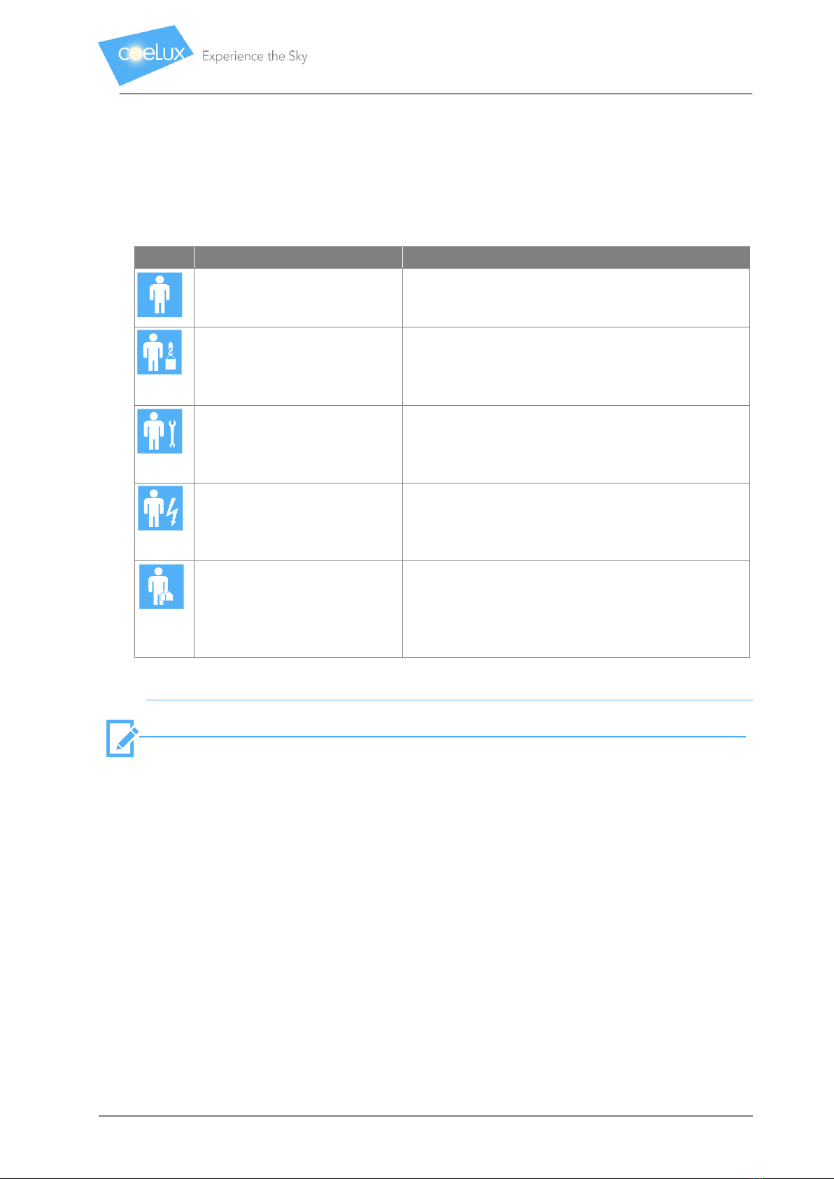
1.5 OPERATORS’ QUALIFICATIONS ..................................................................................................... 5
2PRODUCT SPECIFICATIONS.................................................................. 6
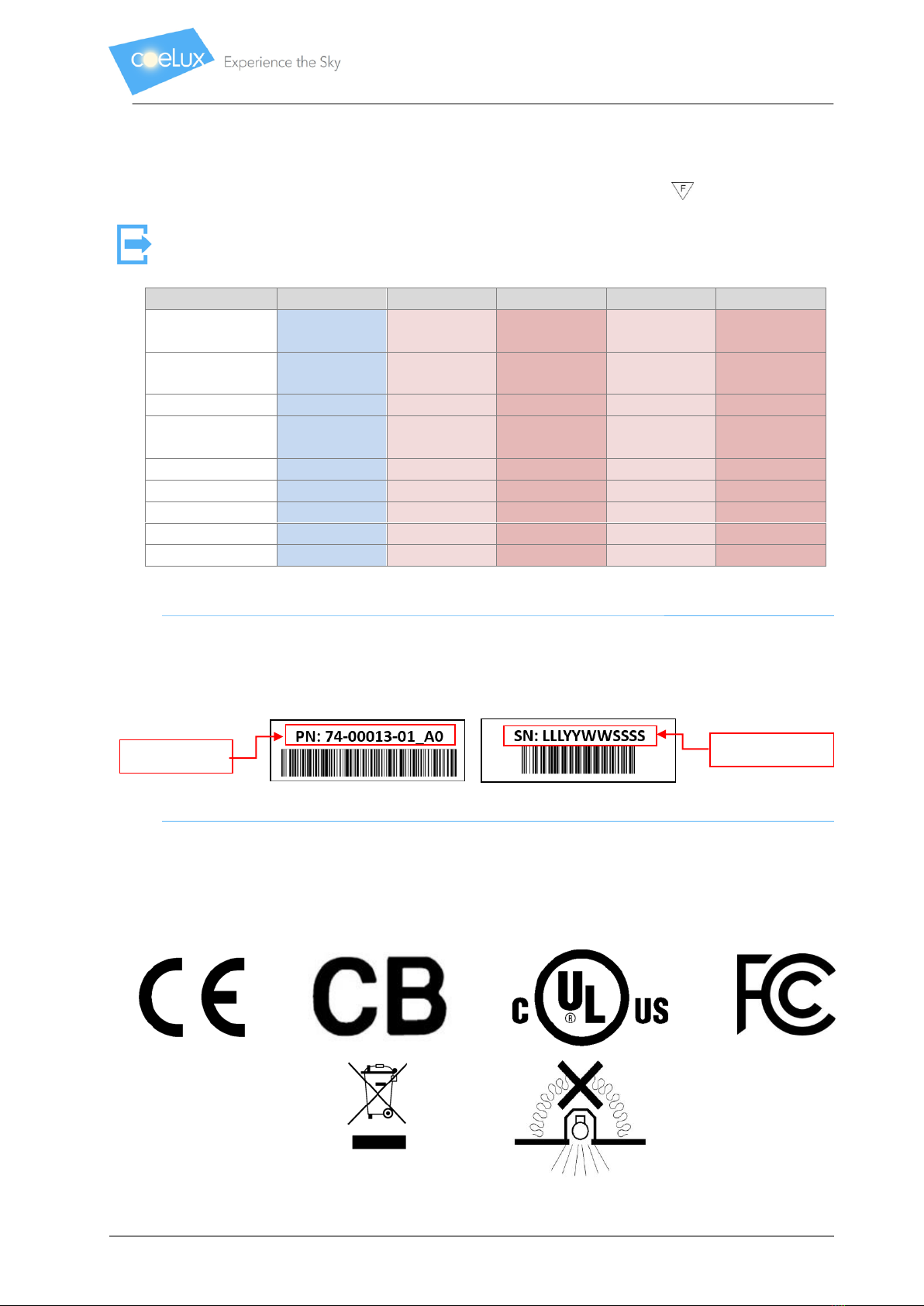
2.1 PRODUCT TECHNICAL DATA, SPECIFICATIONS AND IDENTIFICATION........................................... 6
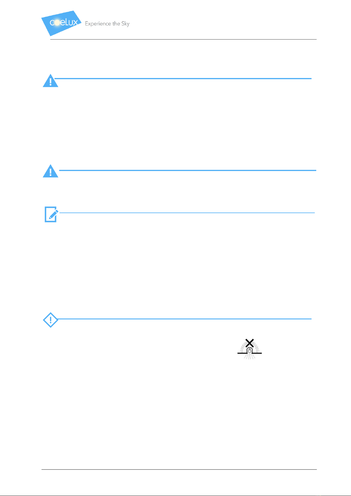
2.2 GENERAL SAFETY WARNINGS ....................................................................................................... 8
2.2.1 OPERATIONS TO AVOID ........................................................................................................ 9
2.3 PACKAGING, HANDLING AND STORAGE ....................................................................................... 9
2.3.1 UNPACKING ........................................................................................................................ 10
2.3.2 HANDLING THE PARTS ........................................................................................................ 10
2.3.3 STORAGE............................................................................................................................. 10
3PRE-INSTALLATION ............................................................................ 11
3.1 PERMITTED APPLICATIONS ......................................................................................................... 11
3.2 DESIGNING THE SPACE ............................................................................................................... 11
3.3 GENERAL INSTRUCTIONS FOR FASTENING ................................................................................. 11
3.4 TOOLS REQUIRED, BUT NOT SUPPLIED FOR INSTALLATION ....................................................... 12
4FASTENING SYSTEM........................................................................... 16
4.1 SAFETY DISTANCES AND VOLUME .............................................................................................. 16
4.2 INSTALLATION KIT....................................................................................................................... 17
4.3 FASTENING PLUGS ...................................................................................................................... 17
5INITIAL CLEANING.............................................................................. 19
6ASSEMBLY.......................................................................................... 21
6.1 ASSEMBLY PROCEDURE .............................................................................................................. 22
6.2 ASSEMBLY SEQUENCE................................................................................................................. 23
6.2.1 STEP 1 ................................................................................................................................. 23
6.2.2 STEP 2 ................................................................................................................................. 24
6.2.3 STEP 3 ................................................................................................................................. 25
6.2.4 STEP 4 ................................................................................................................................. 26
6.2.5 STEP 5 ................................................................................................................................. 27
6.2.6 STEP 6 ................................................................................................................................. 28

Instructions to assemble and install Edition E0 Page 3 of 69
Confidential and Property of CoeLux S.r.l.
6.2.7 STEP 7 ................................................................................................................................. 30
6.2.8 STEP 8 ................................................................................................................................. 31
6.2.9 STEP 9 ................................................................................................................................. 32
6.2.10 STEP 10: assembly of small mirror...................................................................................... 33
6.2.11 STEP 11: assembly of large mirror ...................................................................................... 35
6.2.12 STEP 12: assembly of projector sub-group ......................................................................... 37
6.2.13 STEP 13 ............................................................................................................................... 38
6.2.14 STEP 14A: installation of projector 74-00013-01................................................................ 39
6.2.15 STEP 14B: installation of projectors 74-00062-01/74-00063-01 and module 74-00064-0145
6.2.16 STEP 15 ............................................................................................................................... 48
6.2.17 STEP 16: assembly of fixing kit............................................................................................ 49
6.2.18 STEP 17 ............................................................................................................................... 49
6.2.19 STEP 18 ............................................................................................................................... 51
6.3 VENTILATION CONNECTIONS (ONLY FOR PROJECTOR 74-00013-01) ......................................... 53
6.4 SUPPORT MACHINES FOR INTERNAL AIR CONDITIONING .......................................................... 54
6.5 CHECKS ....................................................................................................................................... 54
7HOW TO OPERATE AND USE ............................................................. 55
7.1 LIGHT INTENSITY CONTROL (ONLY PROJECTORS 74-00062-01/74-00063-01) ........................... 55
7.1.1 THE MOON SCENARIO ........................................................................................................ 56
7.1.2 CONTROLLER....................................................................................................................... 56
8MAINTENANCE .................................................................................. 57
8.1 DISMANTLING THE SYSTEM........................................................................................................ 57
8.2 DEMOLITION AND DISPOSAL ...................................................................................................... 57
9ANNEXES............................................................................................ 58
9.1 ALTERNATIVE INSTALLATIONS: FASTENING OF COELUX®45 HC AT AN ANGLE........................... 58
9.2 EXTRAORDINARY PROCEDURE TO CLEAN THE MIRRORS............................................................ 63
9.2.1 PURPOSE............................................................................................................................. 63
9.2.2 FIELD OF APPLICATION ....................................................................................................... 63
9.2.3 TERMS AND DEFINITIONS ................................................................................................... 63
9.2.4 CASE STUDIES ..................................................................................................................... 64
10 CONTACTS.......................................................................................... 69
11 COPYRIGHT ........................................................................................ 69

Instructions to assemble and install Edition E0 Page 4 of 69
Confidential and Property of CoeLux S.r.l.
1INTRODUCTION
N.B.:
This manual is intended specifically for the technicians in charge of installation.
The operators appointed to assemble and install CoeLux products must read the entire contents
of this manual carefully not only before assembling, installing and starting the unit, but also
before carrying out any maintenance. This manual must always be used and kept safely for any
future eventuality. It is forbidden to remove, tear or arbitrarily modify its parts. The illustrations
and drawings are to be used only for general reference and do not necessarily provide every
precise detail.
The images and technical specifications in the manual are not binding and may be changed
without prior warning.
This manual consists of a total of 69 pages + annexes.
1.1 CONVENTIONAL SYMBOLS USED IN THE MANUAL
WARNING!
This indicates that the operator must pay maximum attention to avoid causing injuries to the
personnel and/or any damage, breaks or fires to the unit.
CAUTION:
This indicates the operator must act cautiously to avoid disturbing personnel and/or possible
damage or malfunctioning of the unit.
N.B.:
This indicates special, technical guidelines or highlights important information.
This indicates a link to parts of the manual or its annexes, or the need to read other separate
documentation.
Other additional symbols may also be used as required.
1.2 ABBREVIATIONS
Sect. = section
Chap. = chapter
Para. = paragraph
Pag. = page
Fig. = figure
Tab. = table
1.3 COMMERCIAL NAMES
CoeLux HE: this refers to the High End product family.
45 HC Systems: this refers to the CoeLux HE product sub-family, consisting of CoeLux® 45 HC,
CoeLux 45 HC_P and CoeLux 45 HC_P_M.

Instructions to assemble and install Edition E0 Page 5 of 69
Confidential and Property of CoeLux S.r.l.
1.4 UNITS OF MEASUREMENT
Unless stated otherwise, the units of measurement are those set by the International System (SI).
1.5 OPERATORS’ QUALIFICATIONS
Logo
Meaning
Function
General operator
Operator without specific skills, capable of carrying
out only simple tasks under the instructions of
qualified technicians.
Driver of lifting and transport
vehicles
Operator qualified to use vehicles to lift and handle
materials (scrupulously following the manufacturer’s
instructions), in compliance with the laws in force in
the country of the user of the unit.
Mechanic
Qualified technician, capable of assembling and
operating the unit, and adjusting, servicing and
repairing the mechanical parts as required. He is not
qualified to work on live electrical systems.
Electrician
Qualified technician, capable of operating the unit,
prepared to carry out all electrical interventions to
adjust, maintain and repair. Capable of operating on
live parts inside electrical cabinets and junction boxes.
Qualified Technician or
Operator
Technician qualified by CoeLux s.r.l. to carry out
operations of extraordinary maintenance, even under
special conditions. He possesses mechanical and/or
electrical and/or electronic skills, depending on the
case.
Tab. 1 Operators’ qualifications
N.B.:
One person may be able to cover more than one role given in the table, subject to adequate
training.
It should be noted that the term “OPERATOR” refers generically to the personnel appointed to
assemble, install and clean the unit.
The term “QUALIFIED PERSONNEL” or “QUALIFIED OPERATOR” refers to those persons, who have
attended specialisation courses, training, etc. and have experience of installing, starting up and
servicing, repairing and transporting the unit.
The term “EXPOSED PERSON” refers to a person whose presence in any area inside and/or near a
machine constitutes a risk for his security, health or safety.

Instructions to assemble and install Edition E0 Page 6 of 69
Confidential and Property of CoeLux S.r.l.
2PRODUCT SPECIFICATIONS
CoeLux HE systems are built-in lighting equipment: partially hidden by the false ceiling, it is
capable of artificially simulating natural light from the sky, sun and the moon (not all products),
even in a completely closed space.
They consist of a LED light source, glass optical components and a CoeLux® plastic plate, all
housed in a single, metal structure.
CAUTION:
The 45 HC systems are designed exclusively for installation and use in internal rooms, which
comply with the requisites listed in the table below. The use of the unit in any way other than
what is described in this manual is prohibited and may cause not only risks to the health and
safety of people, pets and/or goods, but also product malfunction. CoeLux cannot be held liable
for damages to people, goods and animals arising from the incorrect installation and/or use or
which differs from what is described in this manual.
If the rooms are subject to particularly difficult environmental conditions (a daily rise in
temperature of over 15°C and with a maximum relative humidity of over 60%), additional support
equipment will be required for internal air conditioning: in this case, please contact us.
2.1 PRODUCT TECHNICAL DATA, SPECIFICATIONS AND IDENTIFICATION
Specifications
Unit of
measurement
Value
MECHANICAL
CoeLux®45 HC
CoeLux 45 HC_P
CoeLux 45 HC_P_M
Product dimensions
mm
in
3,761 x 2,274 x 968
148.1 x 89.5 x 38.1
3,698 x 2,274 x 949
145.6 x 89.5 x 37.4
Dimensions of the
artificial window
mm
in
1,724 x 870
67.9 x 34.3
Product weight
kg
lb
300
660
ELECTRICAL
Supply voltage
(frequency)
V
(Hz)
100 - 240
(50/60)
Connections
-
Phase + Neutral + Earth
Maximum (typical)
absorbed power
W
300 (270)
Insulation class
IEC Definitions
Class I
Mark
CE, UL, FCC, CB
ENVIRONMENTAL (equipment intended for indoor use)
Operating temperature
°C
25°C
Maximum operating
relative humidity
%
95 (non-condensative)
Tab. 2 Product data and specifications

Instructions to assemble and install Edition E0 Page 7 of 69
Confidential and Property of CoeLux S.r.l.
The 45 HC systems have an external, aluminium structure. Different versions are available
according to the projector specifications and whether the moon module is or is not present (Tab.
3). They can also be installed on surfaces which are normally inflammable.
For all technical lighting data, please refer to the product technical sheet. Contact CoeLux S.r.l to
receive it directly or to receive further product details and clarifications.
System Code:
74-00015-01
74-00074-01
74-00075-01
74-00076-01
74-00077-01
Product Name
CoeLux®45
HC
CoeLux 45
HC_P CE
CoeLux 45
HC_P_M CE
CoeLux 45
HC_P UL
CoeLux 45
HC_P_M UL
Marks
CE, UL, CB,
KC, FCC
CE, CB
CE, CB
UL, FCC
UL, FCC
LED projector
74-00013-01
74-00062-01
74-00062-01
74-00063-01
74-00063-01
Projector
cooling
Active
Passive
Passive
Passive
Passive
Metal BOX
74-00004-01
74-00004-01
74-00004-01
74-00004-01
74-00004-01
Panel
03-00001-01
03-00001-01
03-00001-01
03-00001-01
03-00001-01
Large Mirror
03-00003-01
03-00003-01
03-00003-01
03-00003-01
03-00003-01
Small Mirror
03-00002-01
03-00002-01
03-00002-01
03-00002-01
03-00002-01
Moon Module
/
/
74-00064-01
/
74-00064-01
Tab. 3 Versions of 45 HC systems
The LED projector has a label with the Serial Number (SN) and Part Number (PN); please give
CoeLux S.r.l. these numbers for any query.
Fig. 1 Label with Part Number and Serial Number
The relevant standards have been applied to ensure the 45 HC systems comply with the essential
requisites of the Directives 2014/35/EU, 2014/30/EU, 2011/65/EC and 2012/19/EU.
The 45 HC systems also hold UL certification for Canada and the U.S.A. (File E476417) and are FCC
certified (in accordance with CFR 47 part 15 –Subpart B- 15.107 and 15.109).
Part Number
Serial Number

Instructions to assemble and install Edition E0 Page 8 of 69
Confidential and Property of CoeLux S.r.l.
2.2 GENERAL SAFETY WARNINGS
WARNING!
Read the entire manual, as it contains important information to install and operate the unit
correctly.
To avoid accidents or injuries, follow the procedures described in this manual to install and use
the unit. If you do not follow the instructions and warnings given in this manual, the guarantee
will no longer be valid.
Furthermore, CoeLux S.r.l. will not accept any liability for any damages to objects, people and
animals, which may arise from the failure to comply with the instructions and warnings given in
this manual. CoeLux S.r.l. will not be held liable for the incorrect installation and/or assembly or
which does not comply with what is described in the installation manual.
WARNING!
All assembly, installation and testing operations must be carried out only by CoeLux qualified
personnel. The operations to fasten the product to the existing structure must be carried out by
qualified personnel (CoeLux does not deal with this qualification).
N.B.:
Some details regarding how to switch on the product or how to operate it in general may depend
on the choices made during assembly and/or installation.
• The product is not a toy and must be kept out of children’s reach! Install the product where
children are unable to reach it.
• Take care not to leave the packaging material unguarded, as it could be dangerous for
children to play with it.
• The product can be installed and used only in closed, dry, internal rooms, which are not
exposed to condensation and wet.
CAUTION:
• Do not install the equipment in dirty (dusty) rooms, where gas, steam or dust is, or may be
present! Risk of explosion!
• Do not cover the system with thermal insulation materials: More specifically,
in order to maintain the UL certification, the distance between each surface of the product
and any insulating material present in the ceiling must exceed 76 mm (3 in).
• The product must not be subjected to extreme temperatures, strong vibrations or
mechanical stress.
• If you think it is unsafe to operate the product, you must switch it off at the mains and
prevent any incorrect actions. Ask expert personnel to supervise. You should consider it is
impossible to operate when:
- the product is visibly damaged;
- the product does not work or does not work correctly (flickering light, release of smoke
or bad smell, audible crackle, discolouring of the product or the surrounding surfaces);

Instructions to assemble and install Edition E0 Page 9 of 69
Confidential and Property of CoeLux S.r.l.
- the product has been stored in unsuitable conditions;
- the product appears worn or damaged after transport.
• If you have any further questions, please do not hesitate to contact CoeLux S.r.l (see last
page in this manual).
2.2.1 OPERATIONS TO AVOID
• Carry out even partial modifications to the unit or its parts, unless expressly agreed with and
authorised in writing by the manufacturer. Any unauthorised modifications made by the
purchaser and/or installer and/or assembler and/or any other third parties to the unit will
entail the loss of the CE mark and any other certifications. In this event, the guarantee and
liabilities of CoeLux are no longer valid.
• Open the case before disconnecting from the mains supply.
• Carry out any improper, hazardous operations.
• Obstruct the vents or heat dissipation outlets.
• Use inflammable liquids near the equipment.
• Install or repair without using qualified personnel.
• Walk on the system, lean on it or hang on to it throughout the unit’s working life.
• Repeatedly switch the unit on and off over a period of 30 seconds.
2.3 PACKAGING, HANDLING AND STORAGE
The unit is shipped in separate parts, adequately protected and packed in wooden boxes.
Some accessories may be placed in protective cardboard containers to avoid them being lost and
to facilitate transport.
As some of the parts are particularly delicate, you must take great care when loading/unloading
the packages from the transport vehicle and subsequently during handling.
Therefore, these operations must be carried out only by trained and/or qualified personnel, e.g.
crane and fork lift truck drivers.
N.B.:
The drawings and instructions, which accompany the unit, are and remain the exclusive,
intellectual property of CoeLux S.r.l., which keeps all the rights, prohibits their reproduction and
also prohibits simple, even partial sharing with third parties.

Instructions to assemble and install Edition E0 Page 10 of 69
Confidential and Property of CoeLux S.r.l.
2.3.1 UNPACKING
N.B.:
You can start to unpack only after you have carried out the cleaning guidelines (see paragraph
3.5).
As the contents are fragile, we recommend you take maximum care.
1 Check the material delivered corresponds with the contents of the shipping documents. If
anything is missing or incorrect, contact CoeLux S.r.l. immediately.
2 Once you have opened the box, remove the various system parts from the internal
packaging.
3 Proceed to carry out a careful, scrupulous, general check to identify any damage to the unit
during transport. All damage must be immediately notified in writing to the haulier and the
manufacturer. Do not continue to unpack until you are authorised to do so by CoeLux S.r.l.
4 Proceed to assemble as indicated in Chapter 4.
5 Save and dispose of all the packaging material in compliance with the measures of the laws
in force.
2.3.2 HANDLING THE PARTS
All the component parts weigh less than 25 kg and can, therefore, be lifted and handled
individually without using lifting devices.
As the contents are fragile, we recommend you take maximum care.
We advise all operators involved in the operations described in this manual to use adequate
personal protective equipment (PPE), e.g. gloves, safety shoes, etc.
2.3.3 STORAGE
Store the unassembled unit in a closed room, protected from bad weather and under the
following environmental conditions:
- Temperature between -20°C and +50°C.
- Relative humidity below 30% at 40°C and 90% at 20°C and, in any event, non-condensative.
- Atmosphere with clean air, with no acids, corrosive gases, salts, etc.
The unit must be accurately protected from dust and sunlight using protective covers and
stored away from any possible accidental impacts.

Instructions to assemble and install Edition E0 Page 11 of 69
Confidential and Property of CoeLux S.r.l.
3PRE-INSTALLATION
WARNING!
All assembly, installation and fastening operations for the 45 HC systems and structural elements
must be carried out according to the laws, regulations, technical standards and codes in force in
the country in which the product is installed.
The guarantee is not valid and CoeLux declines any liability for any damage which may arise, if
this instruction is breached.
The 45 HC systems must be fastened to the existing structure by qualified personnel, selected by
and under the responsibility of the installer or user.
3.1 PERMITTED APPLICATIONS
The 45 HC systems were designed to be installed in internal rooms with a minimum floor
thickness of 3,200 mm (126 in). Subject to any different, specific legislation, the recommended
end height of the false ceiling is between 2,200 (86.6 in) and 3,200 mm (126 in).
You must check the minimum permitted height of the false ceiling in every room.
WARNING!
The 45 HC systems are not suitable for installation in open areas exposed to bad weather and in
places, which do not comply with the environmental requisites given in Table No.1.
If the 45 HC systems are used in environments subject to specific legislation (undergrounds,
tunnels, etc.), an assessment must be made by competent personnel. Contact CoeLux S.r.l. to
receive guidelines for any specific project.
3.2 DESIGNING THE SPACE
The 45 HC systems light space very differently compared to traditional lighting and imitate a
permanently sunny window. Prior to installation, you need to calculate where the main beam
will be directed, as it will not be possible to subsequently modify the direction of the light.
To use the product correctly, we advise you to ensure the artificial lighting is compatible with
the natural light, to which the space in question is exposed (from any windows, skylights, etc.)
When you are preparing to install the 45 HC systems, you must envisage an access trapdoor in
the false ceiling (closed by a locked door) and the relevant space above it to permit
maintenance operations (see Paragraph 5 LIFTING, FASTENING, CONNECTIONS AND CHECKS).
3.3 GENERAL INSTRUCTIONS FOR FASTENING
The 45 HC systems must be fastened to the ceiling via a system consisting of a sub-structure
hanging from the aforementioned ceiling, on which you will place the 45 HC systems.
Procedures to assemble, lift, fasten and start up the 45 HC systems must comply with the
instructions in this manual. They must also comply with the relevant, applicable legislation in
force on installation and on health and safety in the work place.

Instructions to assemble and install Edition E0 Page 12 of 69
Confidential and Property of CoeLux S.r.l.
3.4 TOOLS REQUIRED, BUT NOT SUPPLIED FOR INSTALLATION
The table below gives a list of tools required to install the 45 HC systems, but which are not
supplied in the assembly kit.
Tool
Quantity
Notes
Image
Impact drill
1
With bits to drill
concrete, reinforced
concrete and metal.
Screwdriver with
clutch
At least 1 for each
worker.
With bits for 13 mm
nuts and 10 mm
screws (Phillips).
Suction cups to handle
the mirrors.
2
Vacuum cleaner
1
Electrical plug and
socket adapters

Instructions to assemble and install Edition E0 Page 13 of 69
Confidential and Property of CoeLux S.r.l.
PPE (Personal
Protective Equipment)
One for each worker.
Helmet, goggles,
shoes, gloves, etc.
Always follow the
legislation in force in
the country of
installation.
Ladder, compliant with
the legislation in force
At least 2
Height >3.5 m
Screwdrivers, scissors,
cutters, pliers,
hammers
Phillips screwdriver
with handle at least
20 cm long
1
Fixed, tube,
scaffolders spanner
1 set.
Specifically 10
and 13 mm.
Allen keys.
1 set.
Specifically 4
and 5 mm.

Instructions to assemble and install Edition E0 Page 14 of 69
Confidential and Property of CoeLux S.r.l.
Laser level
.
1
Tape measure
1
Silicone gun, with
transparent silicone
cartridge
1
Anti-mould acrylic
silicone
Electric extension
cable
At least 1
Triple-pole, 25 m-long
Insulation tape
At least 1
Black
Battery torch
1

Instructions to assemble and install Edition E0 Page 15 of 69
Confidential and Property of CoeLux S.r.l.
Sunglasses
category 3 or 4
1
Foldable gazebo (as
required: see
Chapter 5).
1
Minimum dimensions
5 x 4 m
Platform trolley to
move the assembled
equipment
At least 4
Dark-Box Support
At least 6
Please read Chapter 7
ASSEMBLY.
Lifting device, suitable
for the work load
(300 kg).
4
Lift trolley
4
Hoist
Tab. 4 Tools required, but not supplied

Instructions to assemble and install Edition E0 Page 16 of 69
Confidential and Property of CoeLux S.r.l.
4FASTENING SYSTEM
WARNING!
The 45 HC systems must be fastened to the existing structure by qualified personnel selected by and
under the responsibility of the installer or user, according to the instructions in this chapter and to
the safety measures in force in the place of installation. If you do not follow the instructions and
warnings given in this paragraph, the guarantee will no longer be valid.
CoeLux S.r.l. supplies an installation kit, certified by a structural engineer for the products in its
range: to this regard, please read paragraph 4.2.
CAUTION:
If you do not use the CoeLux installation kit, the installer will be responsible for the structural
certification of the suspension system. CoeLux S.r.l. declines any liability for the use of any
alternative suspension system to the one offered.
4.1 SAFETY DISTANCES AND VOLUME
For the system to operate at its best, the louvre thermally coupled to the LED source needs to
exchange air with the surrounding environment. If the air within the false ceiling can be regulated
and is not dusty or humid, the free volume of air around the LED projector must be at least 1.5 m3.
Conditions are much better if the air can circulate freely around the entire installed product: thus
we highly recommend leaving at least 100 mm free space around all the system surfaces. Please
refer to Tab. 2 para. 2.1 for the overall dimensions of the system.
You must ensure access to the projector to allow for maintenance. Therefore, you need to make an
opportunely positioned trapdoor with adequate dimensions (restrictions shown in Figure 2).
Furthermore, you need to ensure there is an opportune work area around the light (the optimum
distance of the projector from the walls is at least 50 cm).
Fig. 2 Installation diagram for 45 HC systems. Dimensions in millimetres (inches)
Floor
False ceiling
Trapdoor
600x600
(23.6x23.6)
Max 300
(11.8)
Free
space
Structural
ceiling
Light beam
Range
2200 –3200
(86.6 –126)

Instructions to assemble and install Edition E0 Page 17 of 69
Confidential and Property of CoeLux S.r.l.
UL certified systems require the distance between each surface of the product and any insulating
material present in the false ceiling to exceed 76 mm (3 in).
WARNING!
UL certification will become invalid if this distance is not complied with (NON-IC INSTALLATION
TYPE).
WARNING!
If support machines are required for air conditioning, a suitable housing must be prepared for
them, which ensures the safety volume around the projector is maintained and access (via the
trapdoor) for their maintenance is not blocked. If the housing and the electric socket are over 30
cm (11.8 in) away from the inspection trapdoor, you must create an additional trapdoor to enable
any maintenance to be carried out.
4.2 INSTALLATION KIT
WARNING!
The 45 HC systems must be fastened to the existing structure by qualified personnel, selected by
and under the responsibility of the installer or user, according to the safety measures in force in
the place of installation.
CoeLux declines any responsibility for any breach of the instructions and warnings listed here.
The installation kit supplied by CoeLux S.r.l. consists of:
- 4 L-plates to fasten to the ceiling via 2 anchor points (PN 73-00153-01)
- 4 M12 1500 mm threaded bars. A 140x60x5 plate with an 11 mm fastening hole (PN 73-
00156-01) is welded at each end.
- 4 120x120x5 flat fastening plates (PN 73-00152-01)
- 2 50x2270x5 horizontal tie rods (PN 73-00155-01)
- 4 M8 bolts, 4 M10 bolts, 8 M12 nuts and washers
4.3 FASTENING PLUGS
First, make the holes to anchor the fastening plates to the ceiling (Figure 3).
WARNING!
Each plug anchored to the load bearing structure of the building must be able to support a traction
stress of at least 1.6 kN.
Next, fasten the L plates to the ceiling and connect them to the M12 threaded bars, as shown in
Figure 4.

Instructions to assemble and install Edition E0 Page 18 of 69
Confidential and Property of CoeLux S.r.l.
Fig. 3 Anchor system - View from below
Fig. 4 Recommended anchor system - Fastening of L-shaped profiles and threaded bars
Ceiling fastening
plate with 2 anchor
points
[73-00153-01]
140x60x5 plate
welded to the
threaded M12 bar
with 11 mm
fastening hole
[73-00156-01]
M10 nut (8.8)
M12 threaded bar
maximum length
1500 mm
(adjustable)
[73-00156-01]
2228 (87.7)
2391 (94.1)
2308 (90.9)
2660 (104.7)
100 (3.94)
2580 (101.6)
80 (3.15)
80 (3.15)
841 (33.1)
1196 (47.1)

Instructions to assemble and install Edition E0 Page 19 of 69
Confidential and Property of CoeLux S.r.l.
5INITIAL CLEANING
All product components must be carefully cleaned to achieve the best performance from the 45
HC systems.
The 45 HC systems must be assembled indoors, out of bad weather, in a clean, dry environment.
CAUTION:
Avoid installing 45 HC systems in a dirty environment, as this could compromise operations. If the
environment is dirty or dusty, you must follow the specific cleaning instructions given below. You
do not need to follow these instructions for a clean environment without any dust, although you
should use polyethylene sheets to cover the floor in the assembly area.
It is of fundamental importance during the assembly phase to take great care to avoid
contaminating each component. Dust deposits on internal surfaces, dirt on the CoeLux® panel or
on the optical parts, for example, could prevent the product from performing at its best. Regular
cleaning is essential to maintain the performance of the equipment (please read paragraph 7
MAINTENANCE).
CLEANING INSTRUCTIONS
We have prepared specific cleaning instructions to enable you to assemble even in very dusty
environments. These instructions envisage the use of a specific kit, supplied together with the
product (cleaning kit No. 38-00002-01). The kit consists of the following materials:
- N° 6 polyethylene sheets (5x4 m) to create a clean chamber, in which to assemble.
- N° 1 spray bottle containing a specific dust collector
- N° 2 pairs of cotton gloves and
- N°15 cotton cloths to handle and clean the optical parts.
The instructions are as follows:
1Use the polyethylene sheets to create a clean chamber (preferably beneath the fastening
area) with minimum dimensions 5x4 m.
2 Then, run the vacuum cleaner and wash the clean chamber floor;
3 Carry out cycles of dust collection and floor cleaning: spray the special dust collector liquid
inside the clean chamber, wait for approximately 10 minutes, run the vacuum cleaner over
the floor and repeat this procedure 2 - 3 times (depending on the existing level of
cleanliness);
4 Lay two 5x4 m polyethylene sheets (one on top of the other) on the floor of the clean
chamber (place any covers or filling to protect the floor UNDER the aforementioned
polyethylene sheets) and join them to the sheets used for the walls of the chamber.
6 Spray the dust collector inside the clean chamber once again.
7 Assemble the dark-box inside the clean chamber.

Instructions to assemble and install Edition E0 Page 20 of 69
Confidential and Property of CoeLux S.r.l.
N.B.:
Open the boxes and clean the various dark-box components outside the clean chamber. If the
ceiling of the room is too high and the walls are too wide to fasten all 4 corners of the clean
chamber, use a gazebo as a support structure for the chamber walls.
If you have to assemble more than one piece of equipment, the polyethylene sheet structure
must be dismantled when you have completed assembling one box and recreated with new
sheets following the cleaning instruction procedure.
CLEANING THE COMPONENTS
All the components of the equipment must be cleaned immediately before their assembly.
All the optical parts must be handled with special care. Delicately remove any dirt so as not to
damage the optical surface and ensure the best performance.
We recommend you begin by cleaning gently and then proceed with more decisive, aggressive
cleaning to remove any contamination, if required.
CAUTION:
Incorrect cleaning could cause irreparable scratches on the optical surfaces.
If the surface is damaged, stop installation and contact CoeLux S.r.l to request a new replacement
part.
When assembly is complete, any visible dirt must be removed from all the internal, metal parts,
from the optical outlet and from the ventilation holes of the LED projector.
CLEANING THE MIRRORS AND THE COELUX® PANEL
CoeLux S.r.l. supplies the mirrors and the CoeLux® panel inside a specific packaging. When you
clean these parts, do not touch the surfaces with your fingers or with the sewn edge of your
gloves.
CAUTION:
You must always wear the cotton gloves provided in the cleaning kit to handle these surfaces.
Other manuals for 45 HC P Series
1
This manual suits for next models
5
Table of contents
Other CoeLux Lighting Equipment manuals