Coffee Queen SLIM LINE User manual

Rev. 090914
S / EN
Slim Line Service Manual
SLIM LINE
Juice Machine
Din återförsäljare / Your retail dealer
...............................................................................
...............................................................................

Listofcontents page 2
Generaldescription page 3
Dispenser description of parts page 4-7
Installationandusersinstruction page 8-11
Maintenanceandcleaning page 12
Handlingandcleaninginstructions page 13
Maintenanceandcleaning page 14
Troubleshooting page 15-16
TechnicalDataandNotes
ElectricalSchematics
Exploded View page 19-20
Spare parts list page 21
List Of Contents Index
Main Index
page17
page18
2

General!
Read the instructions carefully before you start working with this equipment.
The equipment should be installed and serviced by trained staff
Dispenser description for Slim line
Slim Line is a dispenser for cooling water and mixing juice concentrate
to a ready to drink product. The dispenser is for
two non-carbonated
drinks and chilled water.
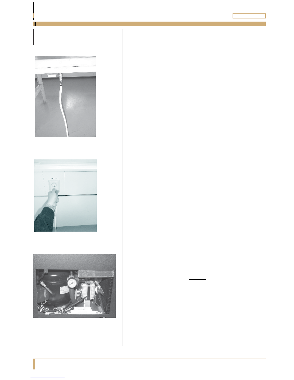
The dispenser is connected to the water mains by a pressurized tube and to
an electric wall socket by a power plug.
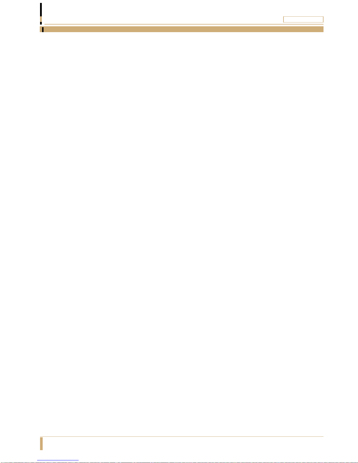
The water-pressure is adjusted with the water-regulator and the pressure is
displayed on the manometer.
The water is chilled by the cooling-block, which in its turn is chilled by the air-
cooled compressor.
The water-temperature is adjustable with a thermostat.
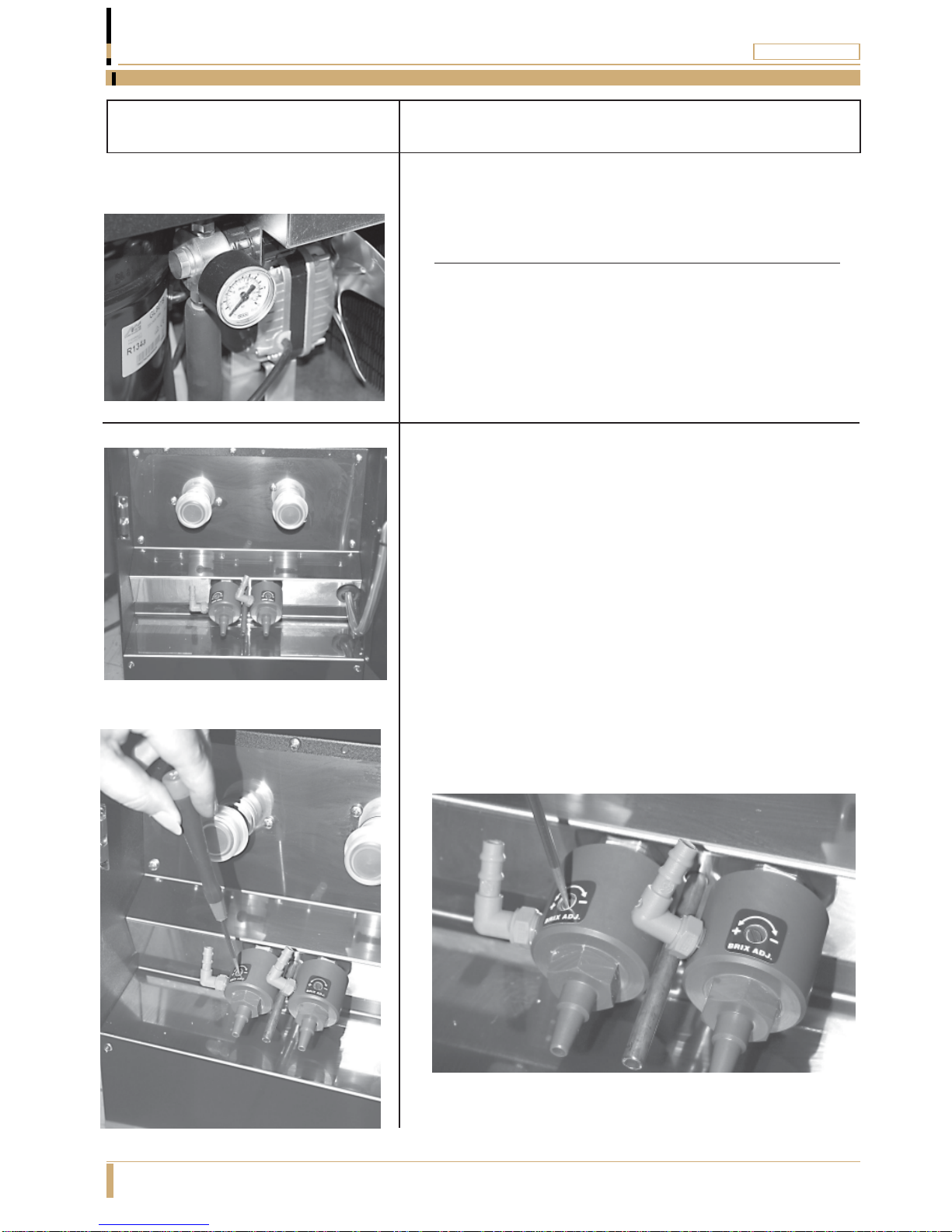
The mixing ratio product/water is adjusted with the ejectors.
Pushing one of the four buttons on the front panel dispenses the mixed
product or water.
3
General Page 3
General Operating Outline
Where fitted the decanter function is operated via the 3 buttons located on
top of the front door.

Picture description
Water-regulator with manometer
Thewater-regulatorcanbeadjustedupto 6bar.
The minimum pressure is 2,2 bar.
Note!Whenadjustingthepressure,dispenseproduct.
Venturi ejector
Themixingratioisadjustedontheejectors.Whenwater
flowsthroughtheejector, theconcentratemixeswiththe
water.
Themixingratiois regulatedon theejector.Thereare
twokinds,onefor productswithcells,andone for
productswithoutcells.
Turntheadjustmentscrewsaccordingtothelabelonthe
ejector in order to increase or decrease the amount of
concentrate.
4
Description Dispenser Parts Page 4

Picture description
Water valve
TheWatervalveisconnectedtotheejectorand
opensthewater-flow.
Push-button
Thepushbuttons onthefrontpanel
controlsthewater valves.
Useonlyonebuttonata time.
5
Description Dispenser Parts Page 5

Picture description
Transformer
The transformer is a 230 / 24 V (55VA).
Thetransformersupplies24V tothemagnetic-valves.
Thermostat
Thethermostatkeepsthetemperaturewithincorrect
range.Factoryadjusteddonotadjust,thismaycause
damage and water leakage in the dispenser.
Illumination
Behindthefrontpanelthereisa low-energyfluorescent
lamp with the effect off 24 W.
Thefluorescentlampis a PL-lamp.
Description Dispenser Parts Page 6
6

Dispenser description of parts
Picture description
Front panel
Thefrontpanelis dividedinthreeparts.
Two plastic sheets (made off acrylic and opaque) and in
betweentheseafilm.
Allpartsare removable.
Drip-tray
The drip-tray is made of stainless steel with steel bars.
It is possible to connect drainage to the drip-tray.
Large particle-filter
Alarge particle-filter is fitted between the cooling block
andthewatervalves.
It is possible to rinse the filter if needed.
Description Dispenser Parts Page 7
7
Removal of the front panel is necessary when setting the
timers when the machine is fitted with decanter function.

Picture description
Unpack dispenser from the packaging and ensure
that nothing is damaged.
Place the dispenser to it´s position. Note:
The dispenser weights about 35 kg.
Don’t lift by door/front panel.
Allow a space of min. 40mm around the
frame for air circulation.
Makesurethatthedispenserlevel.
Adjustment can be made with the adjustable feet .
Adjustments
8
Installation & User Instructions Page 8
Locating the machine

Picture description
Connect the water-hose from the dispenser to the
cold water mains (do not forget seals).
Turn on the water and check for leaks.
Note!
It is strongly recommended to use some sort of
water isolator in the water line in case of an
emergency leakage.
Connectthepower-plugtothewallsocket.
Now the compressor starts and the front panel
lights up.
Thewaterpressureisfactoryadjustedto
2.2bar, whichis thecorrectworkingpressure.
Checkby pressing andholding one product buttonand
readingthemanometer.Ifthereisvariationsadjustby
pullingblackknobandturnit untilyougetareadingof
2.2 bar.
9
Installation & User Instructions Page 9
Connection to services

Picture description
Place the bag-in-box in the dispenser and connect
it to the pinch solenoid-valve and ejector.
Pushing the centre of the pinch solenoid valve and
sliding the tube in from the side, fixes the tube.
Cut the tube to correct length and push it onto the
elbow connector on the ejector.
Place a cup under the outlet pipe.
Dispense a glass of product by pressing
the push-button.
Check that the brix-value (mixing ratio) is
okay, if not adjust.
Toadjustthebrix,usetheadjustmentscrewontheejector.
The dispenser is now ready to use
10
Installation & User Instructions Page 10
Initial settings

Picture description
11
Installation & User Instructions Page 11
Decanter Setting
To adjust the factory settings for the decanter first
remove the front panel from the door as shown in
the picture.
There is no requirement to disconnect any switches
from the door as the panel will unclip from the frame
and can then be rotated sat against the side of the
machine as shown.
When looking at the 2 timer relays the upper timer is
used to adjust the auto dispense time on product
coming from the left ingredient and the lower timer
sets the right ingredient time.
Normal press and release function is obtained using
the bottom front panel push buttons and decanter
dispense is obtained using the buttons located on
the top of the door panel.
The timers are factory set to the following settings:
Time Range 6-60 seconds
Timer Function B
LEFT STOP RIGHT

Change of bag-in-box
1. Turntheboxso theperforatedsideisturnedupwards.
2. Brake the perforation on the box and place the main pipe
inthepunchedhole
3. Place the box in the dispenser so that the tube points
down towards the pinch-solenoid. Press the end of the
pinch-solenoidand insertthetubefrom theside
4. Checkthetubelengthso thatitwillreach1cmintothe
venturenipple.
5. Ifthetubeistolong,cutittotherightlength.
6. Slipthetubetotheventurenipple.
7. Makesurethatthetubeis not twisted,and shutthe doorto
thedispenser.
8. Placeacup undertheoutlet-pipesanddrawuntilthejuice
comesout.
Daily cleaning
1. Cleaninternalandexternalsurfacewithadampedrag.
2. Usethecleaning-brushtocleantheoutlet-pipes
3. Wetthebrushin waterandputit intheoutletpipefromthe
inside of the door.
4. Cleanthedrip-tray.
5. The drip-tray is made-of stainless steel and can be
washed in a dishwasher.
12
Maintenance Page 12

1. Open the Bag-in-Box at the perforation. Pull out the
silicon tube and the plastic connector, so it is clear of the
box.
2. Place the box inside the dispenser. Press in the pinch
solenoid and slide the tube in to the opening. (Fig 2)
3. Push the tube onto the ejector nozzle. (Fig3)
4. The dispenser is now ready to use.
1. When changing the Bag-in-Box, the dispenser should
be cleaned with hot water.
2. Fill the rinsing bottle with a solution of hot water and a
sanitising agent. Add two drops of washing-up liquid.
Connect the tube to the nozzle and wash it through.
(Fig 4)
3. Wet the brush in a hot water and sterilising solution.
Clean the outlet pipes by pushing the brush all the way
through the pipe and back again. (Fig 5)
4. Rinse the pipes with the water solution from the bottle.
5. Thepinchsolenoidthatthetuberunsthroughshouldbe
cleaned on a regular basis, by pouring a hot water and
sterilisingsolutionoverit.Thiswilldissolveanyresidual
concentrate.
6. Theair inlet(condenser)at thebackofthe machineshouldbe
cleaned from dust on a regular basis by brushing or
vacuumingthegrid.
Fig. 1.
Fig. 2.
Fig. 3. Fig. 4. Fig. 5.
13
Handling & Cleaning Page 13
Changing product

Periodic cleaning
1. Disconnect the bag-in-box tube from the
venture.
2. Fill the cleaning bottle with warm water and
some washing-up liquid and connect it to
the venture.
3. Shutthedispenserdoorandput acupunderthe
outlet-pipesrinsetheventureandtheoutlet-
pipesbypressingtherespectivepushbuttons.
4. Usethecleaning-brushtocleantheoutletpipes
5. Wet the brush in water and put it in the
outlet pipe from the inside of the door.
Return the boxes and connect the tubes to
the ventures.
14
Maintenance & Cleaning Page 14
Cleaning

Problem Probable cause Attend to
Concentrate is
Dripping from outlet
pipe.
The tube is not
properly fixed into the
pinch solenoid valve
Fix the tube properly into
the pinch solenoid valve
Mostly water or only
water coming from
outlet pipe
The tube is kinked due
to incorrect length Cut the tube to correct
length
The pinch solenoid needs
cleaning.
The tube is twisted. Untwist the tube.
Clean pinch solenoid
with hot water.
The bag is empty. Replace bag.
Nothing happens
when I push the
buttons, and there is
no ”clicking” sound.
No power to the valves Check the valve on/off sw.
inside the door.
Thermo fuse in the
transformer has cut.
(On older models, a fuse
has blown).
Remove power to the
dispenser and put it back
on after 10 sec.
(Change fuse).
Nothing happens
when you push the
buttons, and there is a
”clicking” sound.
Water supply turned off Check water supply
Water regulator turned off
or failed.
(Manometer =0 bar).
Check water regulator
(change needle valve in
water regulator).
The cooling coil has
frozen.
(Manometer = max
pressure)
Shut off water supply and
call service.
15
Trouble Shooting Page 15
Fault finding

Problem Probable cause Attend to
The taste is to strong/
weak.
The dispenser is not
cleaned properly. Clean ejector, outlet pipes
and pinch solenoid.
The ejector is not adjusted
correctly.
Dirt in the water valve. Call service.
Call service.
It constantly drips
fluid from the outlet-
pipes.
Call service.
Troubles with cooling
system.
The drinks are not
cold.
Failure in thermostat. Call service.
Failure in cooling system. Call service.
16
Trouble Shooting Page 16
Fault finding

Electrical connection 230 V/50 Hz/ 2,5A
Water connection 3,0mTubewith3/8"internalthread(minimum2,5bar
waterpressure.)
Compressor ElektroluxGL80
Cooling gas HFC-134A Amount to fill 210 gram
Cooling capacity 294 W
Cooling throughput 40 litres per hour
Front light 24 W lamp
Front sign size 265 x 481 mm(16 mm must be transparent,Applies on the
bottom part of the sign.
Dispenser measurement Height 750mm
With 250mm
Depth 550mm
Weight 34 Kg
Note 1. Thethermostatisfactoryadjustedandimproperadjustment
may cause the cooling system to freeze causing damage or
water leakage in the dispenser.
Note 3. It is strongly recommended to use some sort of water isolator in
the water line in case of an emergency leakage.
Note 4. Maximumambienttemperatureintheroomwherethedispenser
is located should not exceed more then 25 C.
Note 5. Ifthedispenserhasfrozen,checkwatertubsandconnections
inside the dispenser before running the dispenser again.
17
Technical Data Page 17
Specifications
Operation Notes Notes
Cooling system Dry block with stainless-steel pipes inside.
Note 2. Cooling system is factory set to 3-4 degree. Control thermostat
knob is adjustable for 3-8 degree range .
Note 6. Differential temperature between on/off 3°C. i.e. compressor
off at 3°C then at 6°C compressor will start the cooling cycle
(this value could be affected if somebody changed the
setting of the thermostat control knob)

18
Technical Drawings Page 18
Wiring schematics
Thermostat
230VAC/50Hz
GND
A1 A2 Jug left button Stop button Jug right button
15 Y1
16 18
Compressor
24VAC
Transformer
Fan
Door light
Starter
A1 A2
15 Y1
16 18
Left button Right button
Middle
button
Left pinch valve Right pinch valve Key switch
Left time relay Right time relay
Left water valve Right water valveMiddle water valve
Electrical Schematic Slim Line DecanterVersion
Thermostat
230VAC/50Hz
GND
Compressor
24VAC
Transformer
Fan
Door light
Starter
Left button Right button
Middle
button
Left pinch valve Right pinch valve Key switch
Left water valve Right water valveMiddle water valve
Electrical Schematic Standard Slim Line
Door light Switch
Door light Switch

19
Technical Drawings Page 19
Exploded diagrams main cabinet
23
34
5
6
16
7
17
18
14
13
23
20 21
22
15
19
29

20
Technical Drawings Page 20
Exploded diagrams cabinet door
8
8
828
24
25
26
27
2
1
10 12
9
11
Standard DoorAssembly
Decanter DoorAssembly
Other manuals for SLIM LINE
1
Table of contents
Other Coffee Queen Juicer manuals