46X-1042(A)
3610 CAMERA TECHNICAL RE ERENCE
PRELIMINARY A
1.0GENERAL DESCRIPTION
This introduction briefly describes overall
characteristics of the amera (figure 1) related to
its installation and operation.
1.1Electrical Characteristics
The 3610 Series provides a small, light-
weight, highly sensitive machine vision D
amera with all electrical connections via a single
rear panel connector.
Setup and control settings are implemented
by a graphical user interface (GUI) communicat-
ing through an RS-232 serial interface with the
amera.
The amera operates in either NTS or PAL
format depending on the model. This amera
operates at an internal clock rate of 28.63636
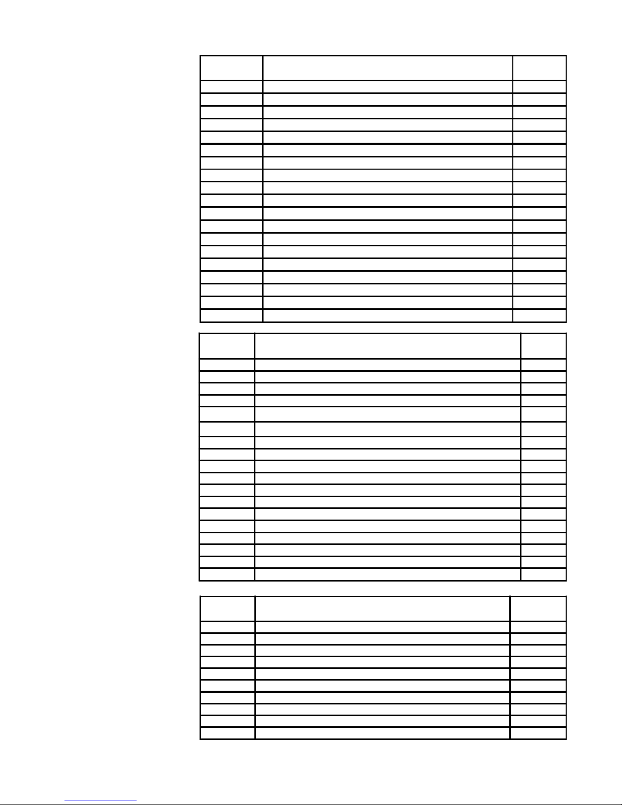
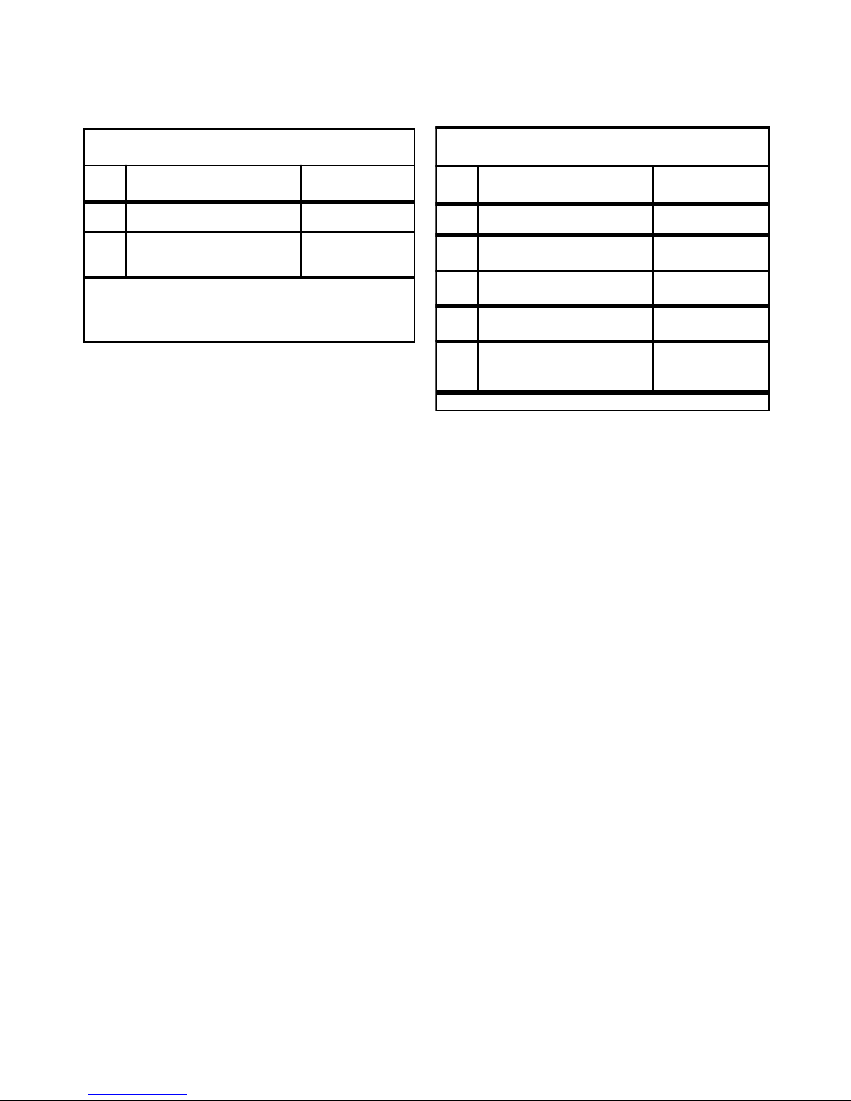
MHz (NTS ) or 28.375 MHz (PAL). Table 1 lists
specifications for this 3610 amera.
Table 2 is a list of major features of the
amera primarily those associated with the
GUI.
The amera is available in two different
operating power configurations: 5 V dc and 12 V
dc. Only manual iris lenses can be used with the
5 V dc amera. The 12 V dc ameras are avail-
able in three configurations: (1) an auto iris
version (2) a dc iris version or (3) a freeze frame
version which requires the use of a manual iris
lens.
1.1.1 Sensor Characteristics
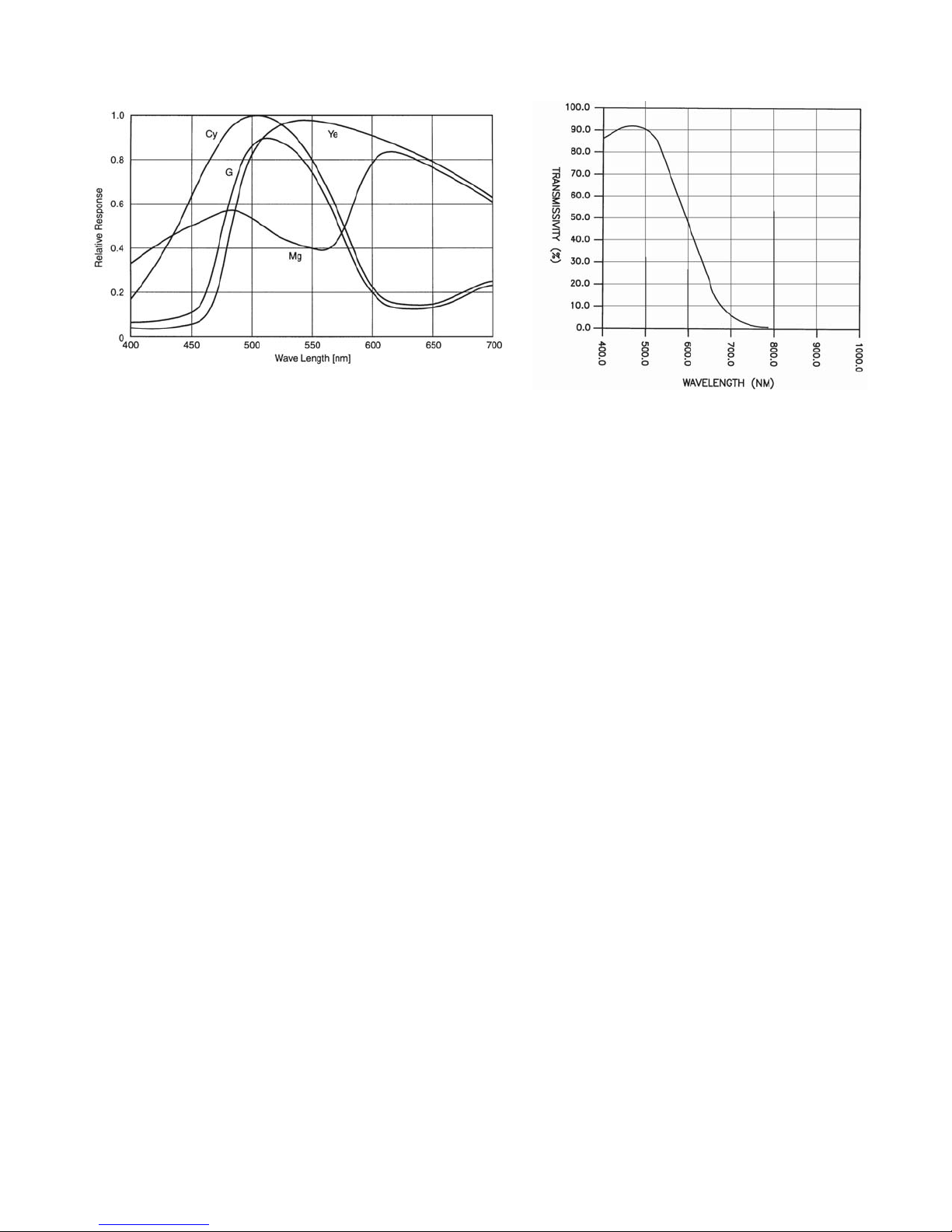
Figure 2 shows the relative response char-
acteristic of the sensor. These characteristic
curves apply to both NTS and PAL sensors.
The curves show yan, Green, Yellow and
Magenta responses.
The chart excludes both lens characteristics
and light source characteristics.
Note however that the IR cut filter shown in
figure 3 will modify the overall response of the
amera to light. This low pass filter starts block-
ing light above about 500 nanometers and at 600
nm passes only about 50 percent. Rolling off the
response at these longer wavelengths minimizes
the effect of infrared on the color response of the
amera.
1.2Mechanical Characteristics
A model number interpretation diagram
appears in figure 4. This diagram shows the
various basic configurations of the amera.
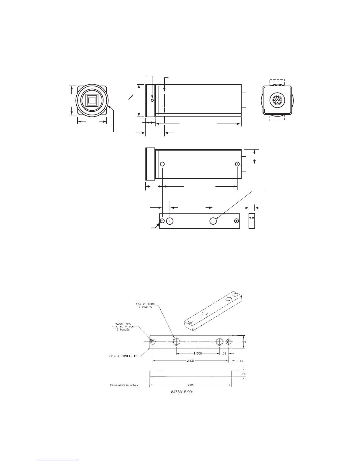
Dimensions for the amera are shown in
figure 5. Figure 6 is a detailed dimensional
illustration for the optional mounting block that
provides threaded 1/4-20 mounting holes. The
amera consists of a main body casting and front
casting assembly.
Interconnections are via a 12-pin connector
located on the rear panel.
NOTE: This equipment has been tested and found to comply with the limits for a lass A digital device,
pursuant to Part 15 of the F Rules. These limits are designed to provide reasonable protection against
harmful interference when the equipment is operated in a commercial environment. This eqiupment gener-
ates, uses, and can radiate radio frequency energy and, if not installed and used in accordance with the
instruction manual, may cause harmful interference to radio communications. Operation of this equipment in
a residential area is likely to cause harmful interference in which case the user will be required to correct the
interference at his own expense.
AUTION: hanges or modifications to this de-
vice not expressly approved by ohu Electronics
could void the user's authority to operate the de-
vice.
This device complies with Part 15 of the F Rules.
Operation is subject to the following two conditions:
(1) this device may not cause harmful interference,
and (2) this device must accept any interference re-
ceived, including interference that may cause un-
desired operation.
CC STATEMENTS