BEAMEX MC6-WS User manual

MC6-WS
Advanced Workshop
Calibrator and Communicator
Applies to firmware version 3.2
Dear user,
We have made every effort to ensure the accuracy of the contents of this
manual. Should any errors be detected, we would greatly appreciate to receive
suggestions to improve the quality of the contents of this manual.
For more detailed technical data about Beamex MC6 Advanced Workshop
Calibrator and Communicator, please contact the manufacturer.
© Beamex 2023
Beamex Oy Ab
Ristisuonraitti 10
FIN-68600 Pietarsaari
Finland
Tel:
E-mail:
Website:
+358-10-5505000
https://www.beamex.com
8860500 / MC6-WSuEng / Version 3.3

Table of Contents - ii
Table of Contents
Feedback..........................................................................................6
Part 1, Introduction.........................................................................7
General.......................................................................................................7
About This Manual............................................................................7
Where am I?.............................................................................8
Typographical Conventions......................................................8
Unpacking and Inspection.................................................................8
About MC6-WS...........................................................................................9
Starting MC6-WS...............................................................................9
Firmware..........................................................................................10
Hardware......................................................................................... 14
General...................................................................................14
Pressure Modules...................................................................15
Front Panel Connection Details............................................. 16
Connectors At The Back of MC6-WS.................................... 17
Memory...................................................................................18
Display....................................................................................18
Batteries..................................................................................19
PC Communication/Calibration software.........................................19
UBS Communication Driver................................................... 20
MC6-WS Related Tools Available for PC...............................20
Options......................................................................................................20
Software Options.............................................................................20
Hardware Modules/Options and Accessories..................................21
Related Products.............................................................................22
Part 2, Active Terminals and Connections.................................23
General.....................................................................................................23
Measurements..........................................................................................24
Pressure Measurement...................................................................24
Connecting and Disconnecting External Pressure Modules...24
Zeroing a Pressure Module....................................................25
Current Measurement......................................................................25
Voltage Measurement..................................................................... 26
Temperature Measurement (Thermocouple)...................................27
Temperature Measurement (RTD)..................................................27
Resistance Measurement................................................................28
Frequency Measurement.................................................................29
Pulse Counting................................................................................29
Switch Sensing................................................................................30
Generations/Simulations...........................................................................31
Changing the Generated/Simulated Value......................................31

Table of Contents - iii
Using the Soft Numeric Keypad.............................................31
Spinning..................................................................................32
Current Generation (Source or Sink).............................................. 33
Voltage Generation..........................................................................34
Thermocouple Simulation................................................................34
RTD Sensor Simulation...................................................................35
Resistance Simulation.....................................................................36
Frequency Generation.....................................................................37
Pulse Generation.............................................................................37
Thermocouple Connections......................................................................38
Part 3, Meter.................................................................................. 40
About Meter..............................................................................................40
Part 4, Calibrator...........................................................................42
About Calibrator........................................................................................42
Tools.........................................................................................................43
General............................................................................................43
Part 5, Documenting Calibrator...................................................47
General.....................................................................................................47
Calibration Software........................................................................48
Calibrating Instruments.............................................................................48
Generating/Simulating the Input Value............................................49
Instrument List.................................................................................49
Instruments.............................................................................50
Plant Structure Levels............................................................51
Instrument List Window Menu................................................52
Instrument Overview Window..........................................................53
Calibrating an Instrument Using MC6-WS...................................... 54
Changing the Pressure Module During Calibration................58
About Fieldbus and HART Device Specifics..........................58
Group Calibration..................................................................................... 60
Collecting Instruments/Functions for Group Calibration..................60
Editing a Group......................................................................62
Calibrating a Group.........................................................................63
Group Settings........................................................................63
Performing the Calibration......................................................64
Calibration Results................................................................................... 65
Deleting Calibration Results............................................................66
Digital Communication and MC6-WS's Instrument Data..........................66
Getting and Editing Mapped Data...................................................67
Preparations............................................................................67
Getting Default Mappings.......................................................67
Customizing the Mappings.....................................................68
Part 6, Data Logger.......................................................................72
General.....................................................................................................72

Table of Contents - iv
Doing a Data Log.....................................................................................73
Configuring.......................................................................................73
Saving and Opening Configurations.......................................74
Starting the Data Log......................................................................75
Viewing and Saving or Deleting the Results...................................76
Viewing Saved Data Log Results....................................................77
Transferring Data Log Results to a Personal Computer................. 78
Part 7, Communicator...................................................................80
General.....................................................................................................80
Warnings..........................................................................................82
Connections..............................................................................................83
Selecting the Instrument.......................................................................... 84
List of Found Devices..................................................................... 84
About Instrument Parameters.................................................................. 86
Instrument Parameters in General..................................................86
Calibrating or Data Logging HART Instruments..............................87
Calibrating or Data Logging Fieldbus Instruments..........................88
Editing Parameters..........................................................................88
Trimming a Fieldbus Instrument......................................................89
Trimming a HART Instrument......................................................... 91
HART Device Description Specifics.........................................................93
General............................................................................................93
Basic View..............................................................................95
Managing Smart Transmitter Configurations............................................96
General............................................................................................96
Tools in MC6-WS............................................................................97
Saving Configurations............................................................ 97
Viewing/Managing Configurations..........................................97
Beamex MC6 Fieldbus Configuration Viewer..................................98
Uploading Configurations....................................................... 99
Linking Configurations to CMX...............................................99
Part 8, Settings............................................................................100
Settings...................................................................................................100
Optional Security Tool............................................................................101
General..........................................................................................101
Applied Restrictions..............................................................101
Part 9, Additional Information....................................................103
Additional Information.............................................................................103
User Defined Pressure Units.........................................................104
User Defined PRT/RTD Sensors.................................................. 105
General.................................................................................105
Callendar van Dusen Formula for PRTs..............................107
ITS-90 PRT Sensor..............................................................108
Factor....................................................................................110
Check Sensor Conversion....................................................111

Table of Contents - v
User Defined Transfer Functions..................................................112
User Defined Steps/Calibration Points..........................................114
Controller Communication.............................................................115
What Can be Done With Controller Communication............ 115
Configuring Controller Communication.................................117
Changing Controller During Calibration................................118
Appendix...................................................................................... 119
Safety......................................................................................................119
Approvals.......................................................................................119
Symbols Used............................................................................... 119
Safety Precautions and Warnings.................................................120
Operating Conditions............................................................120
General Warnings.................................................................120
Warnings Concerning the Lithium Polymer Battery Pack.... 121
Disposal/Replacement of Battery Pack................................121
Charging the Lithium Polymer Battery Pack.........................122
Storing...................................................................................123
Warnings Concerning Electrical Measurement and
Generation........................................................................123
General Warnings Concerning Pressure Measurement.......124
Warnings Concerning High Pressure...................................125
Disposal of Waste Electrical and Electronic Equipment.........................126
Beamex and WEEE...................................................................... 126
Disposal of Battery Pack......................................................126
Service....................................................................................................127
Cleaning MC6-WS.........................................................................127
The Battery Charger......................................................................127
Sending MC6-WS for Service.......................................................127
Firmware Update...........................................................................128
Resetting MC6-WS........................................................................129
Recalibrating MC6-WS..................................................................129
Uninstalling/installing Modules to/from CENTRiCAL.....................130
MC6-WS's Battery Pack And Charger.......................................... 130
Removing/Replacing the MC6-WS Battery Pack................. 130
Index................................................................................................................132

Feedback - 6
Feedback
We want to improve our products and services constantly. Therefore we’d like
to know Your opinion of the product You use. Please spend a moment of Your
valuable time by giving us feedback about the product.
Beamex Oy Ab
Quality Feedback
Ristisuonraitti 10
FIN-68600 Pietarsaari
Address:
FINLAND
E-mail: [email protected]
Fax: +358 - 10 - 5505404
Internet: https://www.beamex.com

Part 1, Introduction - 7
Part 1, Introduction
Things discussed in this part:
• About this manual
• Briefly about MC6-WS's hardware and firmware
• Available software and hardware options
General
Thank you for buying Beamex MC6 Advanced Workshop Calibrator and
Communicator. Because of its versatile features, it really is "more than a
calibrator".
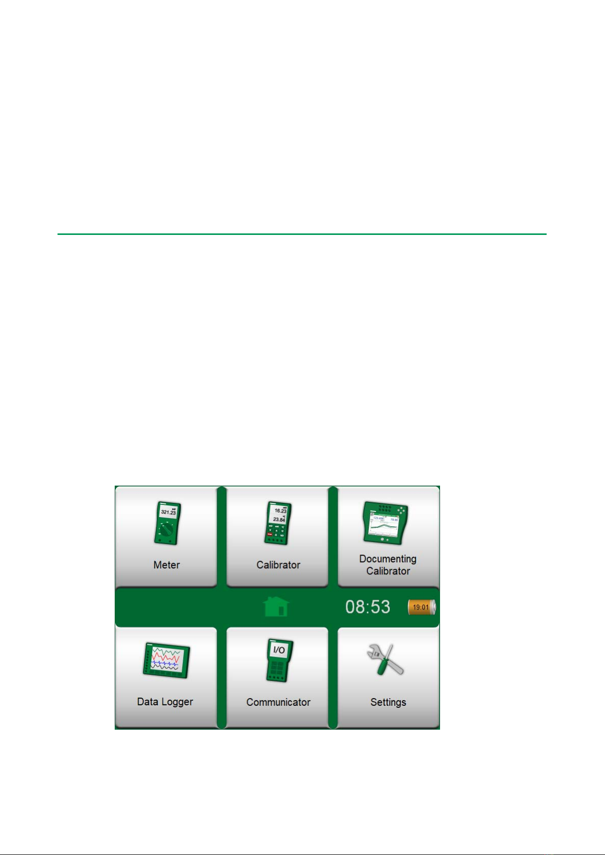
MC6-WS is one device with five different operational modes: Meter, Calibrator,
Documenting Calibrator, Data Logger and Fieldbus Communicator.
Note: Before taking MC6-WS into use, please read the warnings
available in Appendix.
About This Manual
MC6-WS User Manual is divided into several parts as follows:
•Part 1, Introduction discusses general matters.
•Part 2, Active Terminals and Connections. Whatever you measure, generate
or simulate, here's how to make the necessary connections.
•Part 3, Meter introduces the metering tool, which is handy for making quick
measurements. One measurement at a time.
•Part 4, Calibrator. A more versatile tool which allows you to measure/
generate/simulate two things simultaneously etc.
•Part 5, Documenting Calibrator concentrates on instrument calibration using
the full featured documenting calibrator.
•Part 6, Data Logger. Collecting and reviewing data and transferring logged
data to a PC.
•Part 7, Communicator. Invoking digital communication with modern
instruments.
•Part 8, Settings. How to customize MC6-WS and what the About window
contains.
•Part 9, Additional Information. About advanced tools for, e.g. adding custom
pressure units, connecting external devices etc.

Part 1, Introduction - 8
Where am I?
The header of each spread in MC6-WS User Manual informs you of where you
are: The even page shows the part you are in and the odd page shows the main
topic you are currently viewing.
Example of even page header:
2 – Part 1, Introduction
Example of odd page header:
About This Manual – 3
Typographical Conventions
The following typographical conventions apply to MC6-WS User Manual:
Bold text is used in following situations:
• References to User Manual topics and parts,
• MC6-WS keywords, i.e. terms shown in the User Interface and
• other keywords, e.g. the names of fieldbus parameters.
Note: This is a note. Notes typically inform you of something useful
concerning the current topic.
Caution: This is a caution. Whenever you see a caution, read it
carefully and take it seriously. By not observing cautions, you may
damage the calibrator.
Warning: This is a warning. Whenever you see a warning, read it
carefully and take it seriously. By not observing warnings, you may -at
worst- damage the calibrator and/or even risk your life.
Unpacking and Inspection
At the factory each new MC6-WS passes a careful inspection. It should be
free of scrapes and scratches and in proper operation order upon receipt.
The receiver should, however, inspect the unit for any damage that may have
occurred during transit. If there are signs of obvious mechanical damage,
package contents are incomplete, or MC6-WS does not operate according to
specifications, contact the purchasing sales office as soon as possible.
If you have to return the instrument to the factory for any reason, use the
original packing whenever possible. Include a detailed description of the reason
for the return. Read also chapter Sending MC6-WS for Service in Appendix.
For a description of available options, see Options.
Part 1, Introduction - 9
Standard accessories:
• Accredited calibration certificate,
• this User Manual,
• Warranty Card,
• test leads and clips,
• USB cable.
About MC6-WS
Starting MC6-WS
To start MC6-WS, switch the CENTRiCAL on. The MC6-WS will start
automatically. To switch on just the MC6-WS, press and hold the Power button
for a few seconds. The startup procedure ends in Home View. From MC6-
WS's Home View you may advance to any of the available main functions. This
manual contains detailed information of main functions as follows:
•Meter in Part 3,
•Calibrator in Part 4,
•Documenting Calibrator in Part 5,
•Data Logger in Part 6,
•Communicator in Part 7 and
•Settings in Part 8.
Figure 1: Home view
Part 1, Introduction - 10
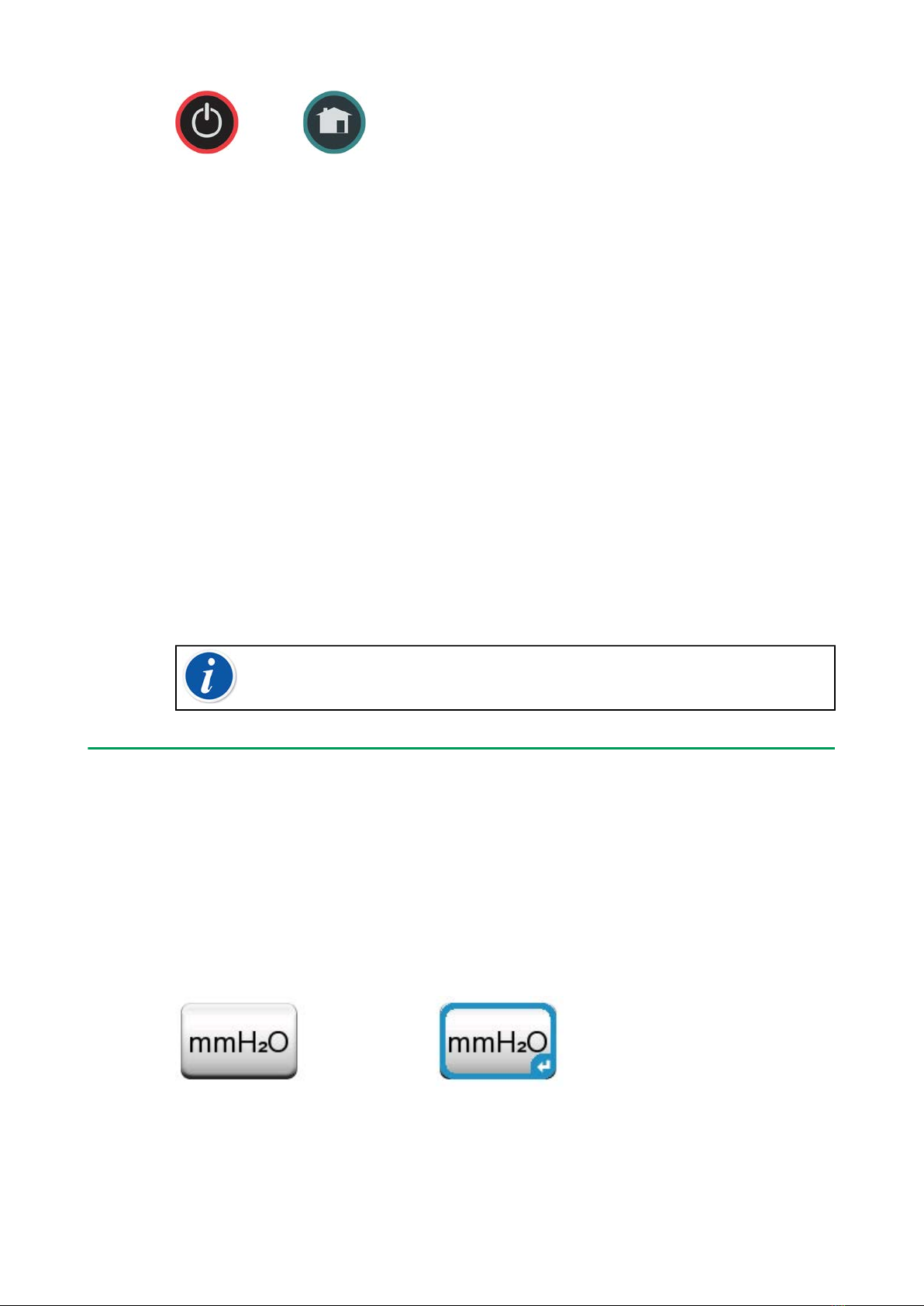
Figure 2: Power button (left) and Home button (right)
With the Home button (see Figure 2: Power button (left) and Home button
(right)) you can always return to Home View from wherever you are.
When MC6-WS is already running, pressing the Power button briefly opens a
dialog with the following options:
•Power Off to shut down MC6-WS in Backup Mode, i.e. minimum power
consumption and full startup procedure.
•Standby to set MC6-WS in Standby Mode allowing faster startup when the
Power button is pressed again.
•Backlight Off to temporarily set the backlight off.
The button on the right side of the dialog:
•Power Management to define Backlight Brightness and other power
management related settings. More in Part 8, Settings.
MC6-WS will shut down immediately when the bench's Main switch is switched
off. The Battery Charging status window will not be displayed. MC6-WS can
still be operated normally on battery power, when the bench's Main switch is
switched off.
Note: Certain main functions are options. They may not be available
in your MC6-WS. More of this in chapter Options.
Firmware
You can interact with MC6-WS by tapping on available buttons/controls
displayed on the touch screen. Optionally: use the hardware arrow keys
to move between the available buttons/controls. The first time you push a
hardware arrow key the Hardware Focus Indicator is displayed (a blue border
around the active button/control). When using the hardware arrow keys, use the
hardware Enter key to select ("tap") a button/control.
Figure 3: Button without and with a Hardware Focus Indicator
Buttons often open a pop-up window for entering data, e.g. a unit button with
the text "mmH2O" opens a pop-up window of available units. Certain buttons
do have special functionality, like "Accept" and "Close" buttons. They close

Part 1, Introduction - 11
a pop-up window and either accept or reject the changes. There are other
buttons, e.g. for going to the next/previous page pages, scrolling through a
wide table of data, removing a number in a numeric field (backspace), clearing
a numeric field, etc. Most of them are familiar since they look similar as in
personal computer software.
Figure 4: Accept button (left) and Close button (right)
One important button is the Menu button which is available in the upper left
corner of almost any window. Tap on it to open a context-sensitive menu with,
among other things.
Figure 5: Menu button (on the left)
Figure 6: An example of an opened menu
Check Boxes are special buttons that are either "checked" or "unchecked".
See Figure 7: Check Boxes, both a checked and an unchecked one. Again, the
functionality is familiar from personal computers.

Part 1, Introduction - 12
Figure 7: Check Boxes, both a checked and an unchecked one
MC6-WS also has some "flat" buttons. They are used in, e.g. lists. The color of
the flat buttons may vary depending on the context.
The following editable fields are available:
•Text Fields,
•Numeric Fields, in certain cases including Spinning and
•Date/Time Fields.
Figure 8: Example of a list with flat buttons
The letters/numbers on all editable fields are blue to indicate that they are
editable. Black texts are descriptive user interface texts that are not editable. An
example of a Text Field and the Text Edit Window are shown in Figure 9: Text
Field and Figure 10: Text Edit window.
Figure 9: Text Field

Part 1, Introduction - 13
Figure 10: Text Edit window
Use of Numeric Fields and Spinning is described in Part 2, Active Terminals and
Connections and Part 5, Documenting Calibrator.
Date Fields are actually special cases of Numeric Fields. Entering the date is
just like entering any numeric value.
Setting MC6-WS's time is a special case of the Spinning functionality. The "Left"
and "Right" arrow buttons move the highlight to another digit. The "Up" and
"Down" arrow buttons change the value of the highlighted digit.
Figure 11: Time Setting window
Part 1, Introduction - 14
Hardware
General
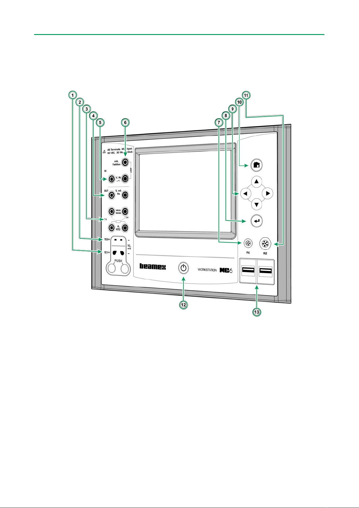
Figure 12: MC6-WS, front view
Legend:
1. Thermocouple connector (TC1) with release buttons. For cables and
standard TC plugs.
2. Thermocouple connector (TC2). For TC plugs with flat contacts.
3. RTD and Resistor connector (R1). An R2 connector is on the top of MC6-
WS.
4. Voltage, Current and Frequency output (OUT).
5. Voltage, Frequency and Switch input (IN).
6. Current Measurement, Loop Supply, HART® and Fieldbus connection
(IN).
7. Connector for External Pressure Modules (PX).
Part 1, Introduction - 15
8. Enter button for selecting the item surrounded with the Hardware Focus
Indicator.
9. Arrow buttons. First press displays the Hardware Focus Indicator. Further
presses move the indicator on the touch screen.
10. Home button. Press this button to return to Home View.
11. R2 connector. A possibility to connect an external RTD sensor to MC6-WS.
See also Hardware Modules/Options and Accessories.
12. Power button, see chapter Starting MC6-WS.
13. Two USB-A connectors for connecting USB devices to MC6-WS. See also
chapter Firmware Update.
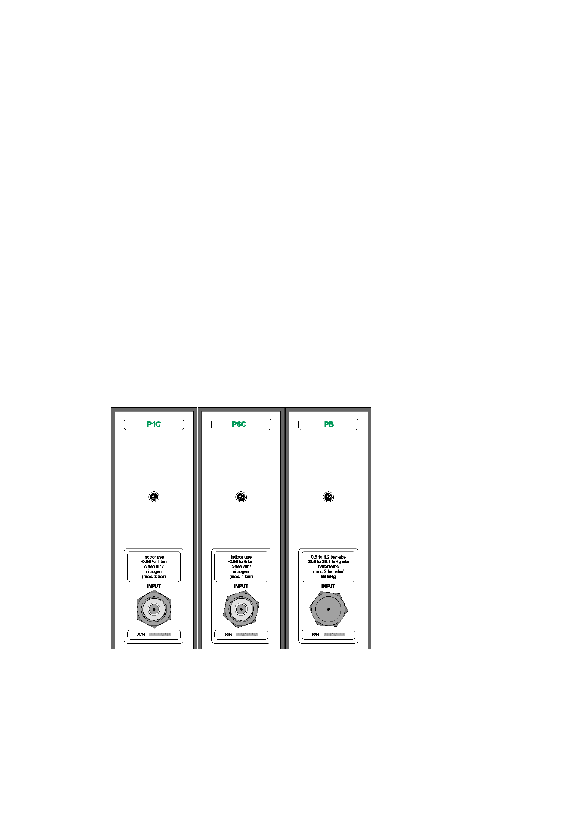
Pressure Modules
MC6-WS supports up to ten pressure modules plus a barometric module
connected to it via a daisy chain communication cable inside the CENTRiCAL.
The amount of modules varies depending on the system at hand. MC6-WS
User Interface refers to Pressure Modules as PX: P1C.
Where:
•X is the ID address of a pressure module (0 to 9)
• P1C etc. are the pressure module types
Figure 13: Example of set of Pressure Modules in CENTRiCAL
The recommended pressure medium for pressure modules is clean air. Clean
non-corrosive liquids may optionally be used in modules with a measuring
range of 20 bar/300 psi or more. Avoid spilling liquid on MC6-WS when
connecting/disconnecting pressure hoses to/from pressure modules.
Part 1, Introduction - 16
To avoid damaging the module, use hand tightening only when connecting the
pressure measurement hoses (max. torque 5 Nm, approx. 3.6 lbf ft). If the use
of tools is required to secure the connection (typically pressure modules with a
pressure range higher than 20 bar), apply the counterforce by placing a 14 mm
(approx. 9/16”) A/F spanner on the flats found in the module’s connector. The
overpressure protection of the internal pressure modules vents to the inside of
the module rack.
Barometric Module
Barometric Modules are shown as PB: PB in the MC6-WS's User Interface.
The connection in front of a Barometric Module is meant for calibration use. The
thread is M5. To ensure valid barometric pressure measurements, do not use
the connection unless calibrating the module.
See Appendix for information on installing and uninstalling Pressure Modules.
Note: Remember to be cautious when working with pressure
and pressure modules. See also chapter Safety Precautions and
Warnings.
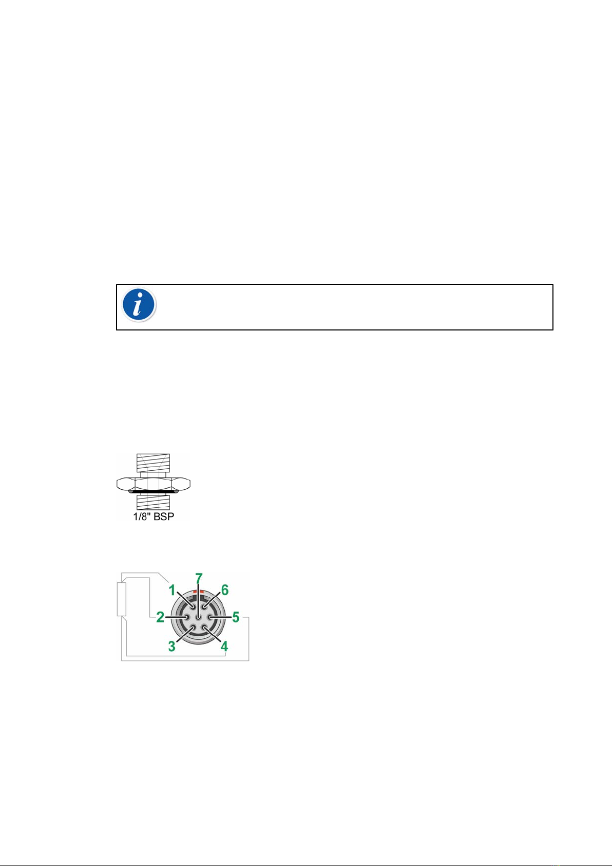
Front Panel Connection Details
If you use other pressure hoses than the one delivered by Beamex, remove the
connector meant for Beamex's pressure hoses and replace them with your own
connectors. The thread available in a Pressure Module's body is 1/8" BSP.
Figure 14: Pressure module connector's thread
Figure 15: Outside view of the female connector in MC6-WS
R2 connector's pin order:
1. Excitation current +
2. Sense +
3. Not in use
4. Sense -
Part 1, Introduction - 17
5. Excitation current -
Note: Leave pins 3, 6 and 7 unconnected in the male connector
meant for MC6-WS's R2 connector.
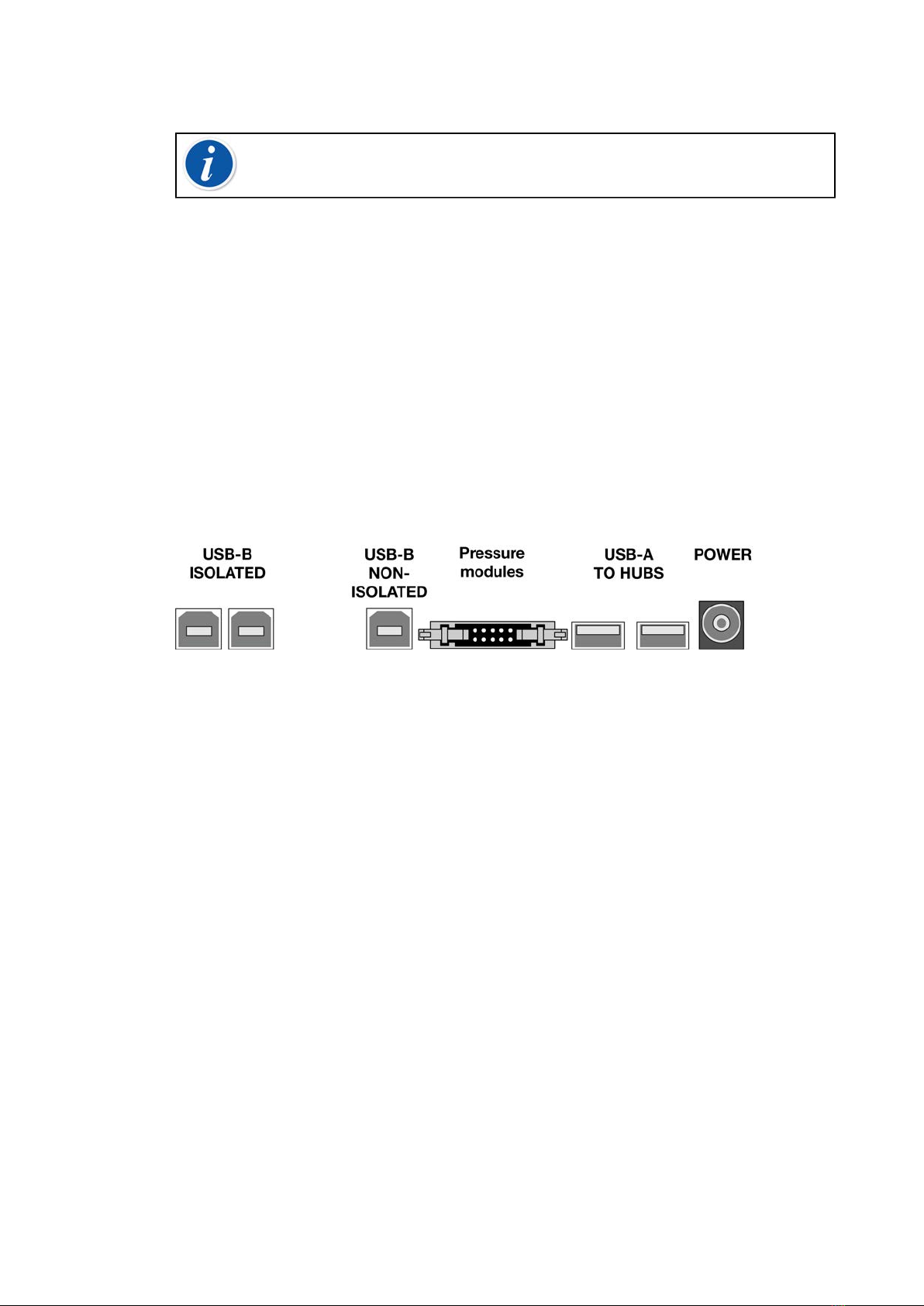
Connectors At The Back of MC6-WS
The rear end of MC6-WS (inside CENTRiCAL Instrument Panel) includes
the same connectors as in a portable MC6. There's also a Pressure Module
connector for connecting Pressure modules in CENTRiCAL.
USB Ports
The need for USB connectors in MC6-WS may be more than is available in
a portable MC6. That is why there is an isolated hub included with MC6-WS
inside CENTRiCAL Instrument Panel. Two of the hub's ports are connected to
the USB-A ports in MC6-WS's front panel allowing communication with, e.g. Dry
Blocks.
Figure 16: Rear view of MC6-WS (inside CENTRiCAL)
A USB-B connector in MC6-WS is connected to USB PC - MC6 connector
located in equipment Panel in the Function Board (under the Flaps).
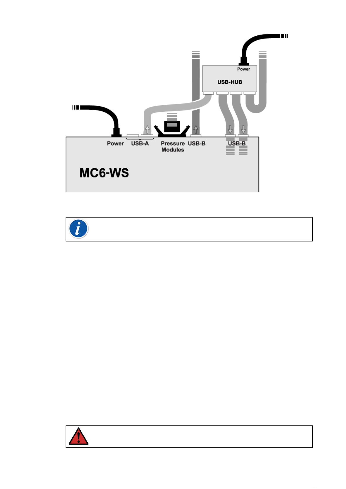
Part 1, Introduction - 18
Figure 17: Defult connections inside CENTRiCAL. Top view of MC6-WS
Note: All USB connectors are USB 2.0 Full Speed ports.
Memory
MC6-WS maintains data very much like personal computers. Data is saved
on a solid state memory that does not need any power to maintain its state.
Solid state memory is shock-proof so the data is not lost when the calibrator
is transported. Also, you can safely save a large amount of instruments,
calibration results and data log results.
Available memory can be used for anything that requires it (e.g. instrument
data, calibration results etc.).
Display
MC6-WS has a backlit 640 × 480 pixel 5.7" TFT touch screen display. Use the
touch screen with your fingers, gloves on or off. Optionally, use a stylus meant
for touch screen use.
See also brightness settings in Part 8, Settings.
Warning: Using sharp tools such as a screwdriver on the touch
screen may damage it. More warnings in Appendix.
Part 1, Introduction - 19
Batteries
MC6-WS has internal rechargeable Lithium Polymer (LiPo) batteries for
powering the internal clock when CENTRiCAL is shut off. The charger is
connected to CENTRiCAL's power supply so the battery is automatically
charged when the CENTRiCAL is on. LiPo batteries do not suffer from the
memory effect, so they may be charged at any time. However, there are some
serious safety issues concerning them, so read Warnings Concerning the
Lithium Polymer Battery Pack in Appendix.
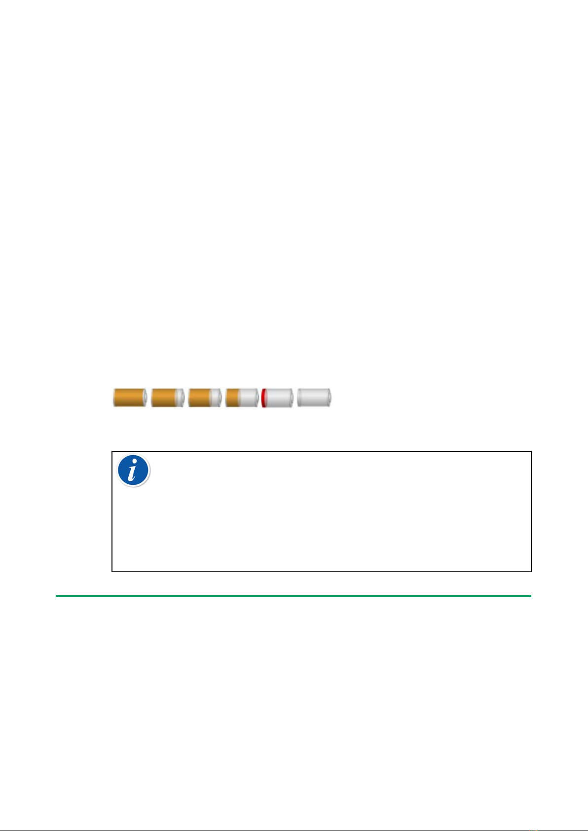
A picture of a battery (or a plug, when charging or running on AC power) is
shown on many of MC6-WS views. The "content" of the battery corresponds to
the approximated charge level of MC6-WS rechargeable batteries.
The maximum operating time of the batteries without recharging varies
depending on the usage of the display back light. The usage of the 24 V
transmitter supply also affects the maximum operating time. Even with constant
maximum load, the standard rechargeable batteries should last for 10 hours. A
good average operating time is 16 hours.
The capacity of all batteries deteriorate with time. If MC6-WS internal clock is
reset, it is time to replace the battery pack with a new one. See Appendix for
information on how to replace the Battery pack.
Figure 18: Full battery - empty battery
Note: A time approximate (hh:mm) is shown on the battery symbol.
During charging it is the charging time left, otherwise it is remaining
usage time.
MC6-WS internal clock/calendar uses a small amount of power even
when CENTRiCAL/MC6-WS is switched off. Remember to check the
capacity of the batteries from time to time although MC6-WS is not
in use. Recharge if needed. Tap the battery icon to open a window
displaying detailed battery/charging information.
PC Communication/Calibration software
Beamex CMX Calibration Management Software supports MC6-WS from
version V2, revision 2.8 onwards and also in Beamex LOGiCAL Calibration
Management Software.

Part 1, Introduction - 20
UBS Communication Driver
MC6-WS uses Windows' generic USB driver (WinUSB) provided by Microsoft.
Supported operating systems: Windows® 7 … Windows® 10. Starting from
Windows 8, the driver installation is self-contained, older versions may require
Windows Update connection.
MC6-WS Related Tools Available for PC
The following tools are available for download at Beamex's website: https://
www.beamex.com. Look for Download Center and Software tools for MC6
family.
•Beamex MC6 Data Log Viewer, for transferring Data Log results to a PC
and viewing them on the PC.
•Beamex MC6 Device Description Installer, for installing new Device
Descriptions of smart transmitters from a PC to MC6-WS.
•Beamex MC6 Fieldbus Configuration Viewer, for downloading smart
transmitter configurations read into MC6-WS to a PC.
•Beamex MC6 Remote Controller, for controlling MC6-WS via a PC.
Options
Software Options
The following software options are available:
•Mobile Security Plus, a solution which ensures the integrity of calibration
data throughout the Beamex ICS solution. This option is also required in the
CMX Calibration Management Software version V2, revision 2.11 or later,
• Multichannel Data Logger,
•Communicator, HART®,
•*) Communicator, FOUNDATION Fieldbustm,
•*) Communicator, PROFIBUS PAtm,
• +) Drivers for External Controllers (Pressure and Temperature) and
•Special Temperature Sensors.
Table of contents
Other BEAMEX Test Equipment manuals


