MEGABRAS MPK257 User manual
Formato: 137mm x 190mm
P. 25
P. 03
Manual de uso
Micro-ohmímetro digital
Digital Micro-ohmmeter User guide

MPK-257
Digital micro-ohmmeter
User’s guide
GF-2072
© 2018 MEGABRAS. All rights reserved.
3

Safety Precautions
This equi ment should be o erated only by qualified and duly trained eo le,
closely observing the corres onding safety regulations and instructions
contained in the resent User guide.
It should be checked that the item to be measured is voltage free.
Before starting with the measurements, be sure that the battery is well
charged and that the line voltage is between s ecified limits.
Do not connect or disconnect the test leads during the measurement.
There are no adjustable arts or arts that can be re laced by the user within
the equi ment. Taking out the Control Panel in order to have an access to the
internal arts may be dangerous as there are high voltages inside, ca able of
causing fatal accidents.
Cleaning of this instrument should be carried out using a soft cleaning liquid,
after verifying that it doesn't attack the lastic arts used in the case and in the
Control Panel of this equi ment.
This equipment should e used only y a trained and competent
person, strictly applying suita le safety rules.
4

Used sym ols
Caution, refer to User Guide.
Battery.
Printer.
USB (Universal Serial Bus).
30 V max. (to ground): indicates the maximum otential allowed
in the terminals during resistance measurements.
Ground rotection: the terminal identified by this symbol is
intended for connection to an external conductor for rotection
against electric shock in case of failure, or the terminal of a
ground rotection electrode.
Equi ment com lies with current EU Directives.
Double insulation: symbol indicates that the equi ment is
classified as Class II (double isolated).
The rubbish bin with a line through it means that in the Euro ean
Union, the roduct must undergo selective dis osal for the
recycling of electric and electronic material, in com liance with
Directive WEEE 2002/96/EC.
5

Index
1. Descri tion.............................................................................................................7
1.1. O erating rinci le..........................................................................................7
2. Control anel..........................................................................................................8
3. Power su ly..........................................................................................................9
3.1. Battery condition.............................................................................................9
3.2. Battery charger...............................................................................................9
3.3. Auxiliary ower..............................................................................................10
4. Settings and Adjustments....................................................................................11
5. Measurement.......................................................................................................13
6. Dis lay messages................................................................................................16
7. Some notes about accuracy................................................................................17
8. Printer...................................................................................................................18
9. Internal memory...................................................................................................18
10. Software.............................................................................................................19
10.1. MegaLogg2 software..................................................................................19
11. Remote control...................................................................................................20
12. Cleaning.............................................................................................................21
13. Re lacement fuse........................................................................................21
14. Technical s ecifications.....................................................................................22
15. Warranty.............................................................................................................24
6

1. Description
The MPK-257 micro-ohmmeter is a ortable, micro rocessor controlled
instrument, used to accurately measure very low contact resistances of
breakers and switches, busbars, transformers and engines windings, etc,
with test currents from 1 mA to 10 A.
Micro rocessor controlled
Kelvin architecture (four-terminal method)
Digital reading, al hanumeric dis lay
U to 4½ digits readings
Powered by rechargeable battery
0.1 µΩresolution
Tem erature com ensation
2000 Ωmaximum reading
U to 10 A current
Remote control through an Android a
1.1. Operating principle
This device uses the Kelvin Bridge architecture, with four terminals,
avoiding testing leads resistance to cause error during measurement. The
o erator may choose test current and the reading is obtained by
com arison through internal high-stability standards. The result a ears
in the al hanumeric dis lay that is very easy to read.
7

2. Control panel
Connection of temperature sensor
Dis lay.
Current terminal (C+).
Potential terminal (P+).
Potential terminal (P-).
Battery charge indicator.
Current terminal (C-).
Selector of ranges and currents.
Battery key. To measure the battery
charge condition.
Safety ground.
Printer Key
Filter key.
Power cord connector.
Fuse.
Auxiliary su ly connector.
Printer.
USB connector.
On/Off switch.
3Test current control.
4Start key.
5Sto key.
6Tem erature com ensation button.
7 Save key.
8

3. Power supply
Mains supply or internal attery powered
Battery: LFP, rechargeable, 12 V - 6000 mAh.
Mains: 220 - 240 V~.
Auxiliary supply: 12 V.
Make sure that the voltage of the mains su ly is com atible with
the voltage su ly of the equi ment!
Before connecting the equi ment to the mains su ly, make sure
that the ower cord is not damaged. If damaged, do not connect
the equi ment to the mains su ly and contact the service center
for re lacing the ower cord.
3.1. Battery condition
The charge condition of the battery can be verified before or during the
resistance measurement. In order to achieve that, the o erator has to
ress the attery key while the equi ment is turned on. The bargra h
shows remaining charge as a ercentile value.
3.2. Battery charger
Charging procedure:
Check that the On/Off switch is in Off.
Connect the equi ment to the mains su ly.
The attery charge indicator ( ) will kee on
lightning with a red light u to com leting the charge. At that oint, it
will change to a green light, being like this u to the equi ment
disconnection from the mains su ly.
If during the charging of the battery the device was switched on, by
activating the key , the charge will be tem orarily interru ted. When
the equi ment is turned off, the charge will restart automatically.
9
The rechargeable battery has no "memory effect" so it can be charged as
many times as desired. On the other hand, its useful life is significantly
reduced if it is allowed to remain totally discharged.
To avoid this effect, charge the battery before storing the equi ment and
do not allow more than 30 days to ass without re eating the charging
rocess, even if the instrument has not been used (The battery loses art
of its charge when it is stored).
At the end of its useful life, the battery must be recycled or dis osed
of ro erly to reserve the environment.
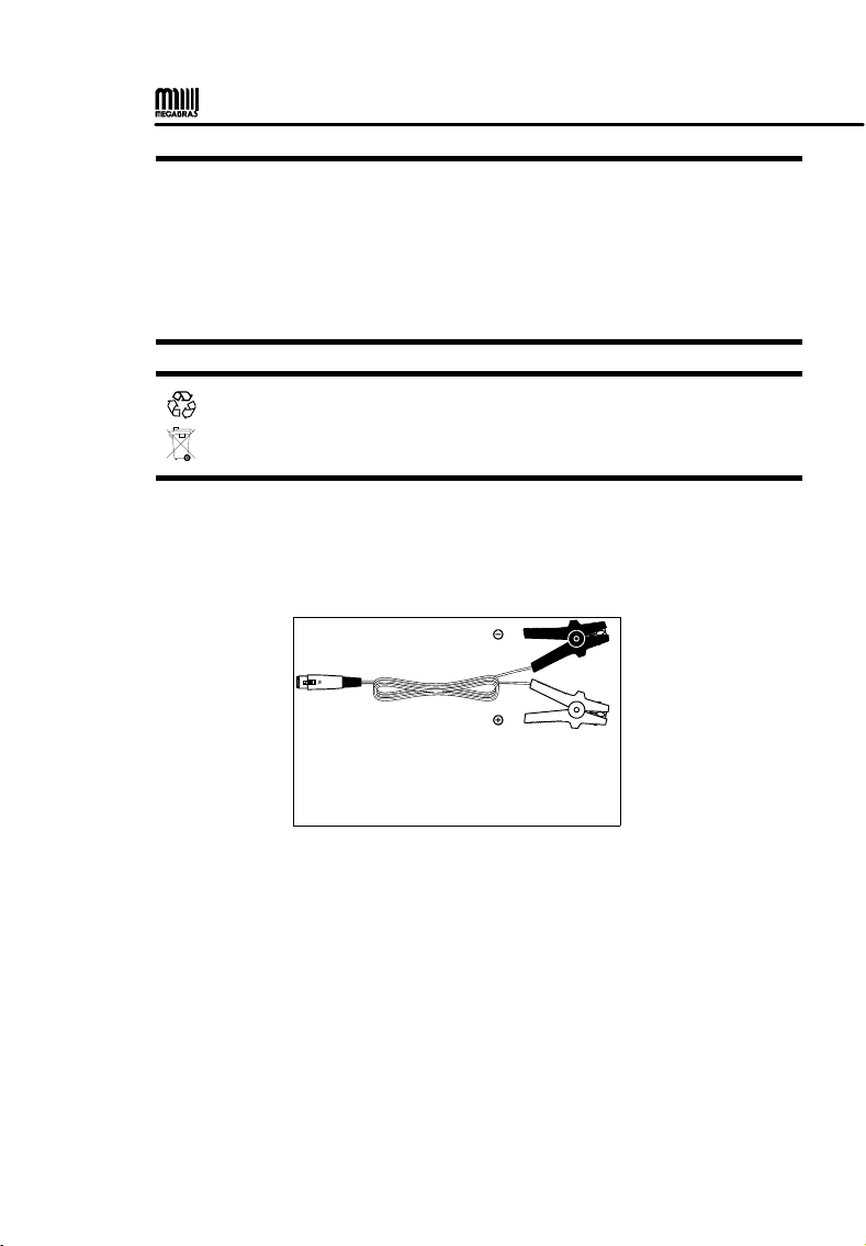
3.3. Auxiliary power
The MPK257 has a 12 V auxiliary ower in ut. This in ut can be used to
charge the battery or to ower the equi ment.
BLACK
RED
To make measurements or charge the battery.
10

4. Settings and Adjustments
This equi ment has a MENU for settings and
adjustments. To access the MENU, ress the
Selector / Adjust ( ).
All navigation is erformed through the and all anel keys are
disabled, with the exce tion of the key that has the function to cancel
and return to the initial screen.
Short ress: O en MENU, o en selected sub-menu /
confirm settings.
Long ress (1.5 s): Go back one level or cancel adjustment.
Change selection / values
Cancel and close the MENU
ATTENTION: The configuration MENU can not be accessed during the tests.
11

Filter
Auto save
Temperature
compensation
MENU SUBMENU DESCRIPTION
SETUP TEST
METAL SELECT ON Allows you to define the type of metal that will be
used in the calculation of temperature compensation.
COMP. TEMPERATURE t allows setting the reference temperature that will
be used in the calculation of temperature
compensation.
AUTO SAVE Save the last measured value in the internal memory
when the test is finished.
LANGUAGE Allows you to change the interface language
between: English, Spanish and Portuguese.
SETT NGS
SET DATE FORMAT Selecting the date format.
SET T ME FORMAT Selecting the time format.
DATE ADJUST Setting the date.
T ME ADJUST Setting the time.
D SPLAY ADJUST Setting the display.
SYSTEM NFO Displays the firmware version and serial number.
MEMORY
USAGE Displays the percentage of internal memory used.
DELETE Deletes all records from memory.
12

5. Measurement
• The User Manual and its res ective safety recautions must be read
and understood before using the micro-ohmmeter.
• The usual safety recautions and safety regulations must be strictly
observed.
• It should be checked that the item to be measured is voltage free.
• To ensure safety, use only the accessories su lied by the
manufacturer.
1. Before turning the equi ment On, connect the test leads to the item
to be measured and to the front anel terminals.
Sim le measurement
The alligator clamps in the drawings are only for illustration.
Sim le measurement with tem erature com ensation
The alligator clamps in the drawings are only for illustration.
13

Measurement with potential risk
Ex .: High voltage circuit breaker under external influence of electromagnetic fields
from nearby energized devices.
The alligator clamps in the drawings are only for illustration.
The safety ground terminal must be connected before making the
other connections to the equi ment.
2. Turn on the device with the On / Off key ( ).
3. The display of the equi ment will show the resentation
message MPK257.
4. The AUTO VERIFICATION message will appear next and then
PRESS START.
5. Select the range and current ( ).
6. Press the key .
7. The message LOW CURRENT will a ear. Turning the control
clockwise will increase the current until reaching the desired
stable value measured on the dis lay or in the bargra h current
indicator.
8. When the current value is greater than 20% of the nominal value
of the scale, the dis lay will indicate the measured resistance
value.
14
9. To activate the tem erature com ensation ress the button.
10. U on com letion of this rocess the display will indicate the
measured resistance value and other test information.
11. The unit of measured resistance shall be ex ressed in Ω (ohms),
mΩ (mili-ohms) or µΩ (micro-ohms).
12. This information can be saved in the machine's internal memory
during and / or after the test sim ly by ressing the save key
.
13. To finish the test ress the red stop key . Do not turn off the
roduct with the power switch without ressing the sto
button .
14. Finally, after all measurements have been com leted, switch the
device off using the on / off switch .
Caution: Never connect or disconnect the test leads with the equipment
in operation. If you have to make any changes to the connection, it must
be done with the equipment turned off.
15
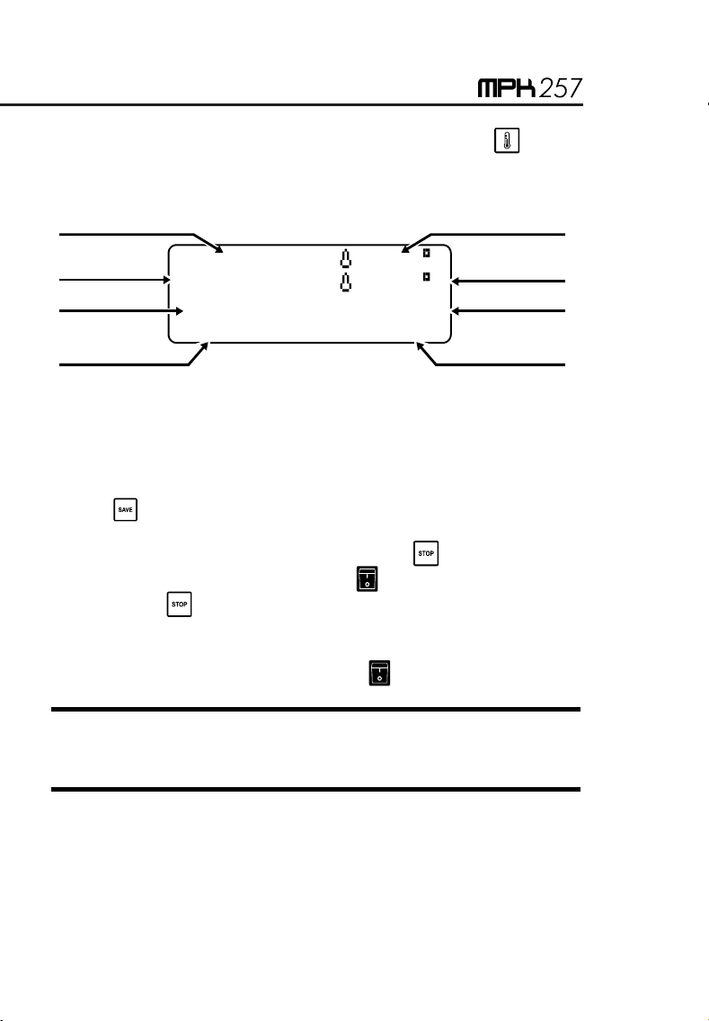
R= 9.876m :25.8 CΩ
Rc: 9.843m :25.0 CΩ
[ ] 8.5 Aίίίίίί
01:22 82mV
Measured resistance
Elapsed time
Reference
temperature
Measured voltage
Test current
Analog current
indication
Resistance
compensated
Measured temperature

6. Display messages
MEGABRAS MPK-257
When turning the equi ment On using the On/Off switch, this
introductory message a ears for a while. During that time, the
equi ment carries out some functional checking.
AUTO CHECK
Indicates that the equi ment is erforming internal checks.
PRESS START
Indicates that the equi ment is able to start a test, for which the o erator
must ress the key .
LOW CURRENT
This warning indicates that the test current is insufficient to erform the
measurement. The control must be turned clockwise to increase
current.
I=MAX
Indicates that the current reached the maximum value.
OVERRANGE
Indicates that the measured resistance exceeds the maximum value of
the selected scale.
16

7. Some notes a out accuracy
In order to obtain the s ecified accuracy, the o erator has to adjust the
test current to a value higher than the 80% and 100% of the nominal
value. For minor currents the measurement is only indicative.
MPK-257 has an auto-com ensation system that automatically eliminates
the error roduced by internal offset. Thus, it is not necessary to carry out
measurements by reversing the olarity in order to com ute the average
value. Nevertheless, if the o erator sus ect that there is a difference of
tem erature between the contact oints that would can generate
thermoelectric voltages, it is necessary to carry out two measurements by
reversing the current cables and so, the circulation sense of the current
through the resistance under measurement. The resistance value to be
measured will be the average between the values in one sense and in the
contrary (direct and inverse current).
17
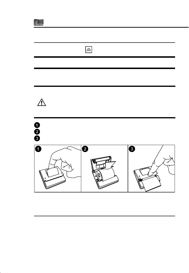
8. Printer
To rint a result, ress the key during a measurement.
ATTENTION: Don’t ull the a er. The rinter can be easily damaged.
This rinter uses 2.2” (57 mm) -wide thermal a er, which comes in a
1.18” (30 mm)-diameter reel.
Precautions
• Perform the rocedures below with the equi ment turned off.
• Disconnect the equi ment from the mains su ly and remove
the ower cord.
• Disconnect the test leads.
Pull the lever located on the lid.
Insert the a er reel as shown in the figure.
Kee the ti of the a er out of the rinter and close the lid.
9. Internal memory
This device has an internal memory of u to 30,000 measured values
(a roximately 10,000 tests).
18

10. Software
To install the USB drivers required for the communication between PC
and equi ment follow the instructions:
Connect the equi ment in the PC using the USB cable.
If there is an available Internet connection, Windows will silently
connect to the Windows U date website and install any suitable driver
it finds for the device. If no suitable driver is automatically found then
you need to insert the CD-ROM, su lied with the equi ment, in the
PC, run the executable “usb-install.exe” and click in “Install”.
10.1. MegaLogg2 software
This software makes communication between the equi ment and a
com uter with Windows o erative system easier. It makes it ossible to
synchronize the date and time of the equi ment internal clock with the
com uter date and clock, to transfer the stored date, to clear the memory,
to generate test re orts, etc. The installation and o eration instructions
are included in the software.
19

11. Remote control
The MEGABRAS equi ment that have Bluetooth interface can be
controlled remotely via an Android device (smart hone / tablet) running
the a lication.
DISPONÍVEL EM
• ndroid™ and Google Play™ Store is a trademark of Google LLC
• Bluetooth® is a registered trademark of Bluetooth SIG, Inc. worldwide
Minimum smartphone / ta let requirements
- Android 4.1 Jelly BEAN system (API 16) or higher;
- Bluetooth communication.
Pairing
To erform the airing between equi ment and the Android device, follow
the rocedure:
•To enable the Bluetooth, in screen “A lications”, ta "Settings"
> "Bluetooth" and drag the Bluetooth slider to the right.
•To air your equi ment, on screen "A lications", ta "Settings"
> "Bluetooth" > "Search". Select the equi ment and wait for the
end of the airing (If necessary, acce t the automatically
generated assword to confirm or enter the PIN 1234).
20
12. Cleaning
Cleaning of this instrument should be carried out using a soft cleaning
liquid, after verifying that it doesn’t affect the lastic arts used in the case
and in the Control Panel of this equi ment.
To avoid electrical shock, make sure that the equi ment is
com letely dry before Power it On.
13. Replacement fuse
Precautions
• Perform the rocedures below with the equi ment turned off.
• Disconnect the equi ment from the mains su ly and remove
the ower cord.
• Disconnect the test leads.
• Disconnect the equi ment from the mains, un lugging the ower cord.
• With a screwdriver, remove the fuse holder cover, lightly ressing the lid
and turning ¼ counter clockwise.
• Remove the blown fuse and insert a new fuse in the fuse holder cover.
• Place the cover in the com artment and with the screwdriver turn ¼
clockwise or until the fuse holder cover ro erly fits the fuse
com artment.
Fuse Schurter, model SPT 5x20 (Time-lag) 5A/250V. High reaking capacity.
To re lace the fuse, use only the fuse ty e s ecified in the
equi ment.
21
Table of contents
Languages:
Other MEGABRAS Test Equipment manuals


Popular Test Equipment manuals by other brands


Rohde & Schwarz
Rohde & Schwarz SMBV-K361 user manual

PIE
PIE PIECAL 211 operating instructions

ULTIMATE SPEED
ULTIMATE SPEED UAWSB 2 A1 operating instructions

Oakton
Oakton EcoTestr EC1 operating manual

Mecmesin
Mecmesin MultiTest 0.5-dV Service and repair manual

Extech Instruments
Extech Instruments MG320-NIST user manual


