Cojali jaltest TOOLS WST User manual

English 3
Index
Contenido
Index 3
General information 5
1.1 PRODUCT DESCRIPTION 5
1.2 INDICATIONS AND SUGGESTIONS 5
1.3 EQUIPMENT COMPOSITION 6
2.1 CHECK OF CONTINUOUS AND END-OF-PAD/2-WIRE SENSORS 8
2.2 CHECK OF THE WEAR OF BRAKE PADS AND DISCS 8
Procedure 8
2.2.1 END-OF-PAD/ 2-WIRE SENSORS 9
2.2.2. CONTINUOUS SENSORS 9
3.1 TABLE 1. DISTANCE BETWEEN THE DISC AND THE PAD 10

English 4
Index
Reference table 10
3.2 TABLE 2. POSITION OF THE SENSOR SELECTOR 11
3.3 POSITION OF THE SELECTOR FOR DAF, IVECO, MB, SCANIA, (+) 11
3.4 TABLE 4. POSITION OF THE SELECTOR FOR MAN, MERITOR 12
3.5 TABLE 5. POSITION OF THE SELECTOR FOR END-OF-PAD/2-WIRE SENSORS 12
Technical data 13
index nextprevious
Faster access to
any content you
need by clicking
Easy navigation

English 5
General information1
1.1 PRODUCT DESCRIPTION
1.2 INDICATIONS AND SUGGESTIONS
Jaltest WST is a portable equipment of small dimensions made for checking the
correct operation of brake pad wear sensors as well as their state.
It has a selector that enables the user to choose the type of sensor to be checked
and, through a display incorporated to the device, see the voltage value (V) in an easy
way.
It enables reducing considerably the time invested in checks thanks to the cable kit
that provides an optimal connection.
• Use the equipment only as described in the user manual.
• Prevent non-qualified staff from working with this equipment.
• Prevent the equipment from being in contact with liquids, do not use it on wet
surfaces and avoid exposure to the rain.
• Store the equipment and its components in a dry place, away from heat sources
and out of the reach of solar radiation.
• Prevent the equipment from being knocked or falling.
• Switch off the equipment after its use to avoid discharging the battery.

English 6
1.3 EQUIPMENT COMPOSITION
Jaltest WST is formed by an electronic device with a sensor type selector and a com-
plete kit of connectors.
A. Connection
Input port of the cable for the
sensor
B. Display
Display of voltage values (V)
C. Battery status
The orange LED lights up if the
battery is too low
D. Continuous sensors of MAN
and Meritor
E. Sensor type selector
Rotary switch that enables
positioning the type of sensor
F. Wear indicator
-The green LED lights up if the
wear of the brake pads and disc is
correct
-The red LED lights up if the wear
of the brake pads and disc is not
correct
G: Continuous sensors of DAF,
Iveco, Mercedes-Benz, Scania,
others
H: End-of-pad/2-wire sensors
I: Device turned-off
1.3.1 DEVICE

English 8
2.1 CHECK OF CONTINUOUS AND END-OF-PAD/2-
WIRE SENSORS
2.2 CHECK OF THE WEAR OF BRAKE PADS AND
DISCS
1. Disassemble the vehicle wheel if needed
2. Disconnect the connector of the brake caliper sensor
3. Loosen the brake pads with the help of the adapter until they can be
disassembled
Important: The pushers must be at the same height, with a difference below 0.25mm.
Otherwise, the brake caliper must be replaced.
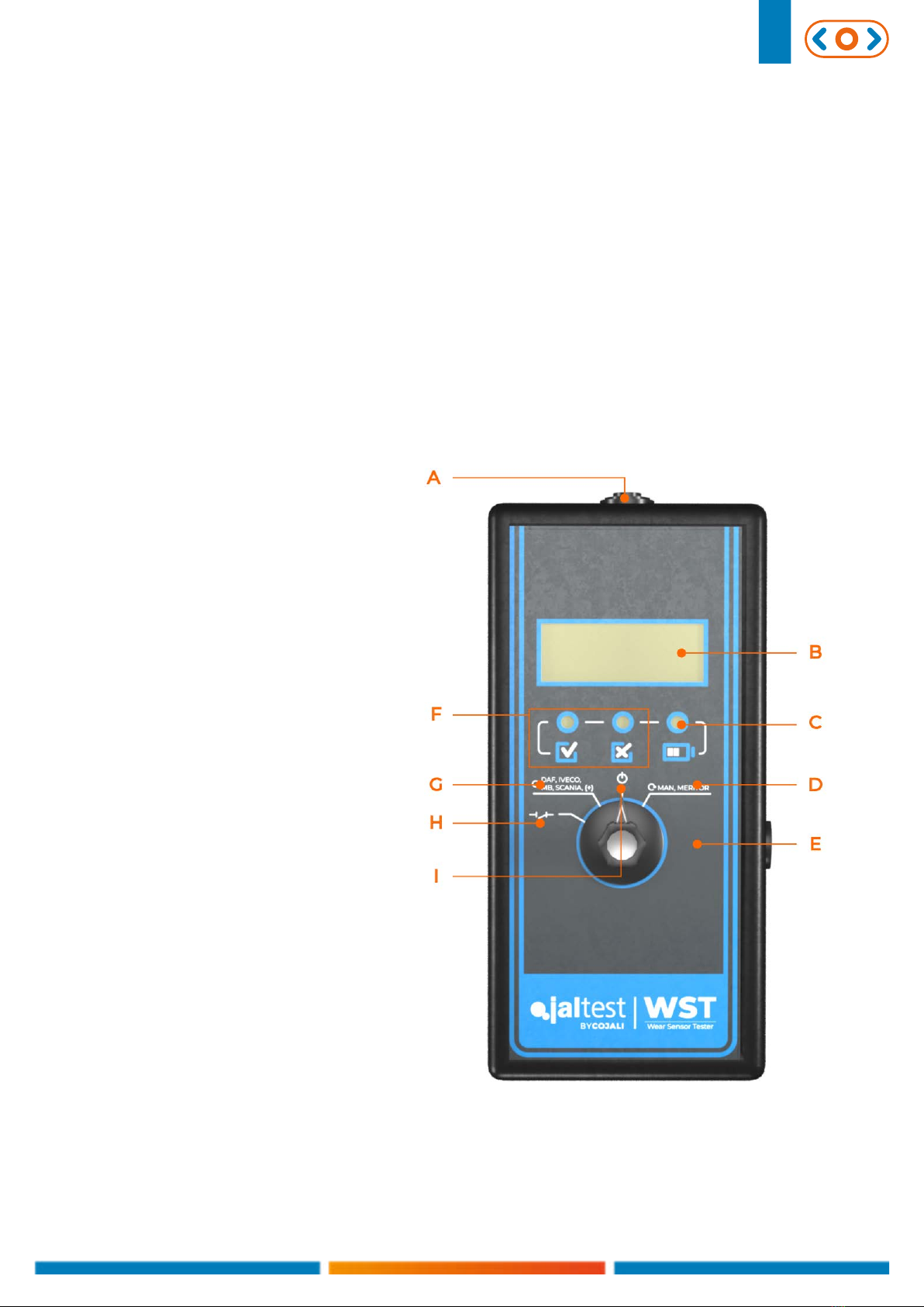
4. Connect the corresponding connector from Jaltest WST to the sensor connector
5. Turn the sensor type selector to the corresponding position. See table 2
6. Adjust the distance between the pusher and the brake caliper according to table
of the selected sensor* and compare the values shown on Jaltest WST with those of
the table (maximum and minimum values)
*Table 3 for manufacturer DAF, IVECO, MB, SCANIA, (+)
Table 4 for MAN, MERITOR
Table 5 for end-of-pad/2-wire sensors
Important: Important: The adjustment spindles should not be totally unthreaded,
since the synchronisation between the pushers would be lost. Never exceed the ab-
solute minimum dimension “L” shown on table 1.
Note:
• If Jaltest WST indicates 0V during the test, check the position of the selector and
the connection.
• If the values are correct and within a tolerance of ± 0.25V, the sensor operates
correctly. Otherwise, the sensor must be replaced.
To check the wear, the brake calipers can assemble 2 types of sensors: end-of-pad/2-
wire sensors and continuous sensors. Depending on the type of sensor, the check
must be performed in one way or another. In any case, the following steps must be
carried out:
1. Disassemble the vehicle wheel if needed
2. Disconnect the connector of the brake caliper sensor
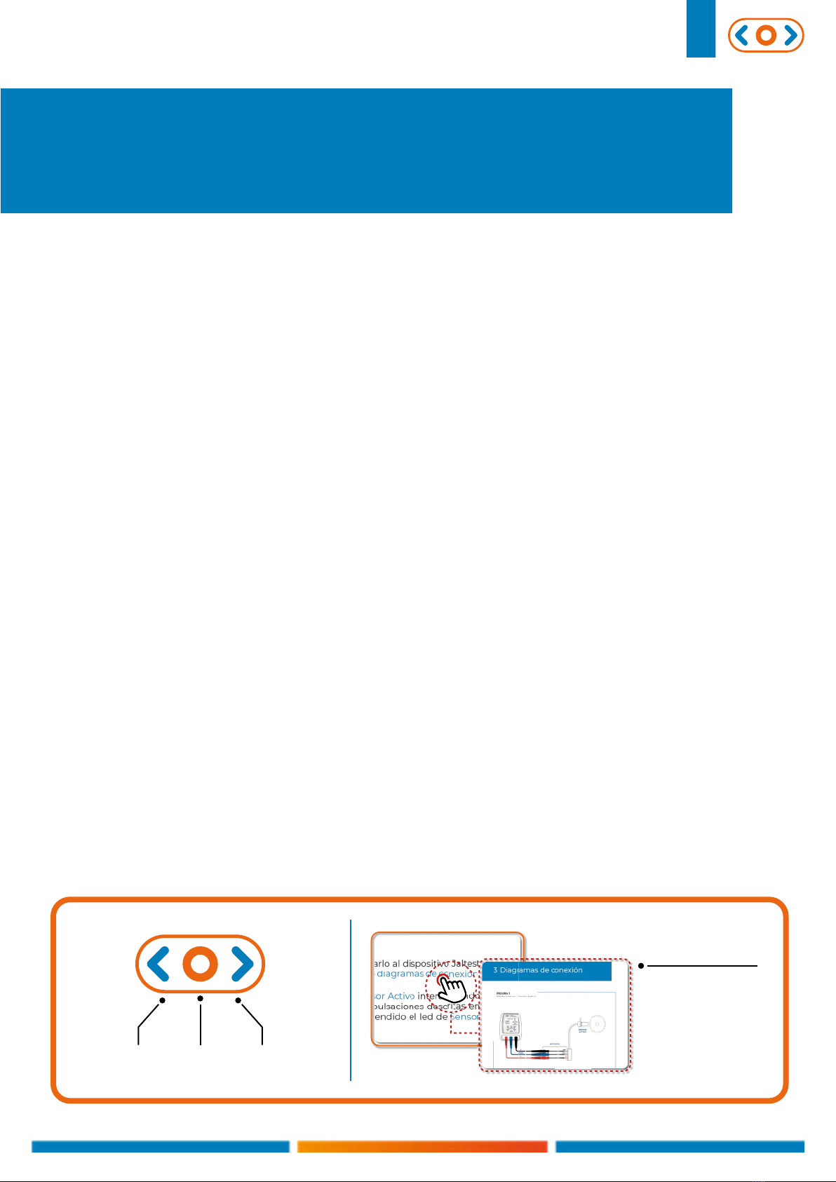
3. Connect the corresponding connector from Jaltest WST to the sensor connector
2 Procedure

English 9
2.2.1 END-OF-PAD/ 2-WIRE SENSORS
2.2.2. CONTINUOUS SENSORS
1. Turn sensor type selector to the position of the end-of-pad/2-wire sensor
2. If the OK LED lights up in green, the wear is correct
3. If the NOT OK LED lights up in red, it must be visually inspected, since Jaltest WST
does not indicate any wear value
Note: If Jaltest WST indicates a value below 0.2V or above 4.8V, the brake caliper
sensor is an end-of-pad/2-wire sensor and, therefore, it cannot be checked with
accuracy the wear state of the pad. The inspection must be performed visually.
1. Turn sensor type selector to the position of the corresponding continuous sensor.
See table 2
2. Compare the value shown with those of table 3 in case of sensors in DAF, IVECO,
MB, SCANIA, (+) and with table 4 or sensors in MAN and MERITOR
3. If the value shown in Jaltest WST is below 2.7V, the OK LED lights up in green
If the value shown in Jaltest WST is above 2.7V, the NOT OK LED lights up in red. In
this case, the wear of brake pads and discs must be visually inspected and it should
be considered to replace them.
Note: If it is a continuous sensor and Jaltest WST indicates a value below 0.2V or
above 4.8V, the component might have an open circuit or a short circuit.

English 10
3 Reference table
3.1 TABLE 1. DISTANCE BETWEEN THE DISC AND THE PAD
Type of brake caliper Maximum distance
“L” (mm)
Minimum distance
“L” (mm)
Absolute minimum
distance “L” (mm)
SB5 / SN5 96 66 64
SB6.../SB7.../SN6.../SN7...
DAF, IVECO, MB, SCANIA, (+) 105 68 66
SB6…/SB7…/SN6…/SN7…/
MAN, MERITOR 105 70 68
SL7…/SM7… 110 73 71
ELSA 1
MAN 103 70 68
ELSA 2
MAN, RENAULT 103 70 68
ELSA 195
VOLVO 103 70 68
ELSA 225
RENAULT, VOLVO 103 70 68
1. Low pad support
2. Brake disc and bushing
3. Axle of rotation
4. Adjustment spindle
5. Pusher

English 11
Type of brake
caliper
Maximum
distance “L”
(mm)
Measured
voltage (V)
Minimum
distance “L”
(mm)
Measured
voltage (V)
Distance variation for
complete turn of the
adjustment screw
(mm/V)
SB5/SN5 96
1
66
3,5
6/0,50
SB6/SN6 105 68 6/0,41SB7/SN7
SL7/SM7 110 73
3.2 TABLE 2. POSITION OF THE SENSOR SELECTOR
3.3 POSITION OF THE SELECTOR FOR DAF, IVECO,
MB, SCANIA, (+)
Measured voltage
Measured voltage
Measured voltage
Distance
Distance
Distance
Wear
Wear
Wear
Position of the
sensor type selector Vehicle or axle manufacturer
Pin
colour of the
continuous
sensor
Information to know if the
operation is correct
DAF, IVECO, MB,
SCANIA, (+)
DAF
DAIMLER
DANA
EVOBUS
HENDRICKSON
HYUNDAI
IVECO
MERITOR
SAF
SCANIA
SOR-LIBCHAVY
VOITH
ZF
OTHERS
SILVER
The voltage values
increase from 1V to 3.5V
lineally between the
maximum and
minimum distance
MAN, MERITOR
Knorr-Bremse
MAN, DANA, SAF, OTHERS GOLD The voltage values
increase from 0.7V to
3.56V lineally between
the maximum and
minimum distance
Meritor
MAN, RENAULT, VOLVO -
END-OF-PAD/2-
WIRE SENSORS
DAF
DAIMLER
ERF
ZF
SILVER The voltage values
change from 0.15V to
5V when the minimum
distance is reached
MAN GOLD

English 12
Type of brake
caliper
Maximum
distance “L” (mm)
Measured
voltage (V)
Minimum
distance “L”
(mm)
Measured
voltage (V)
SB5/SN5 96
≤ 0,15
66
5SB6/SN6 105 68
SB7/SN7
3.4 TABLE 4. POSITION OF THE SELECTOR FOR MAN,
MERITOR
3.5 TABLE 5. POSITION OF THE SELECTOR FOR END-
OF-PAD/2-WIRE SENSORS
Type of brake
caliper
Maximum
distance “L”
(mm)
Measured
voltage
(V)
Minimum
distance “L”
(mm)
Measured
voltage (V)
Distance variation for
complete turn of the
adjustment screw
(mm/V)
SN5 96
0,7
66
3,5
6/0,57
SB6/SN6
SB7/SN7 105
70
6/0,49
ELSA 1 /
ELSA 2 103
ELSA 195/
ELSA 225 16/0,44
Measured voltage
Measured voltage
Measured voltage
Measured voltage
Distance
Distance
Distance
Distance
Wear
Wear
Wear
Wear
Table of contents
Other Cojali Test Equipment manuals