2.2. Use of the calibrator
2.2.1. Automatic calibration
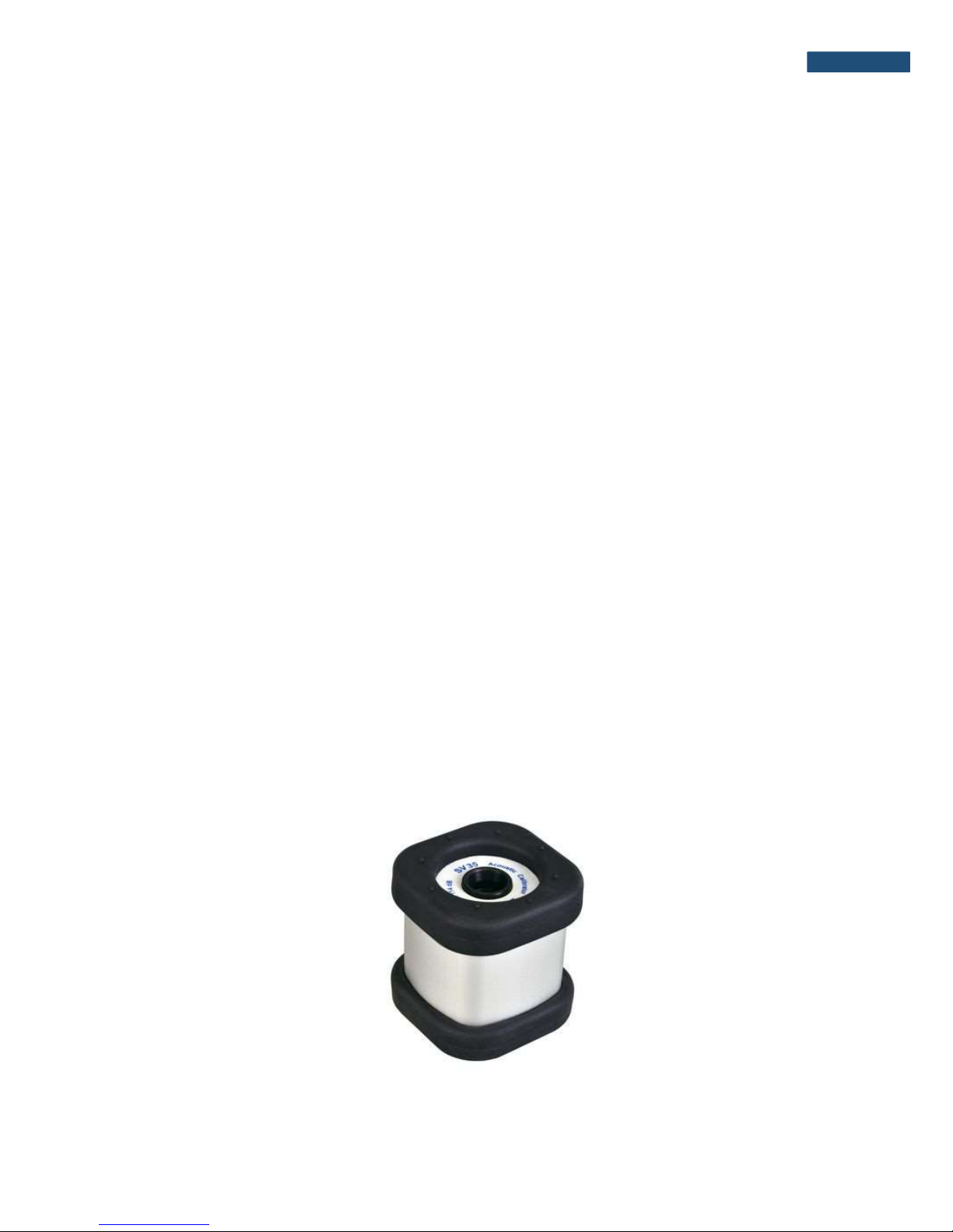
The SV 35A calibrator is equipped with an optical system which detects the presence of
a microphone in the calibrator’s chamber. That allows the calibrator to be switched on
automatically, when it is placed on the microphone and to be switched off when it is
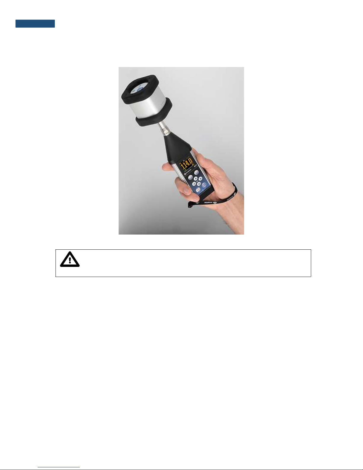
dismounted. For this reason, usage of the SV 35A calibrator is as simple as putting it on the
microphone, performing the calibration and taking it off the microphone.
. Notice: The SV 35A calibrator will always switch on in the range set at the moment
of switching it off.
. Notice: The automatic switching on will not work when the SA30 calibration
adapter is inserted into the calibrators chamber.
Notice: Default range after replacing the battery is 114 dB.
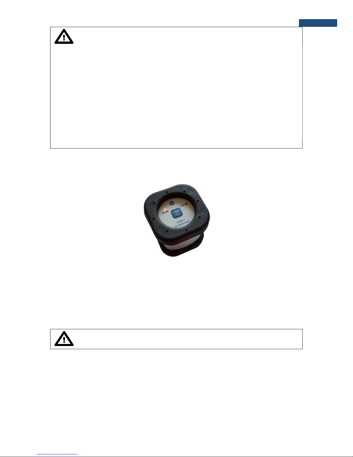
2.2.2. Button functions
The SV 35A calibrator is equipped with a multifunctional button for controlling operation
of the device. The functions of the button depend on the state of the calibrator (ON/OFF) and
on the time of its pressing (see Table 2).
When the calibrator is OFF, pressing the button turns it on immediately. Range
is automatically set to that one in which the calibrator was switched off. If the calibrator is not
put on the microphone within 3-5 seconds from turning on, it will switch off automatically.
When the calibrator is ON, short pressing of the button (less than 3-5 sec.) will cause
switching the range from 94 dB to 114 dB or the other way round. Button pressed longer (over
3-5 sec.) will switch the calibrator off, either when the device is put on the microphone or not.
Either when the SV 35A is ON or OFF pressing the button over 10 seconds and releasing
it will cause full reset of the system. Normally this function is not necessary. It has been
implemented in the case of inappropriate operation of the calibrator caused by external (EM
radiation, subnormal atmospheric conditions, etc) or internal (inappropriate system reset as a
result of battery replacement) factors.
The operation time of the calibrator with a microphone put inside its chamber
is limited to 3-5 minutes. This functionality was added in order to save the battery, e.g. when
the calibrator is accidentally left with the microphone inside.