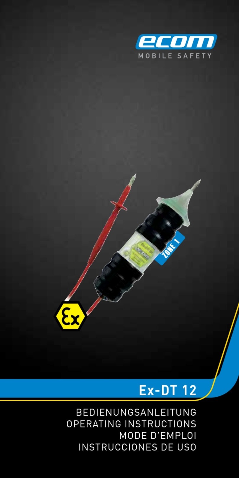
Ecom Ex-DT 12 User manual

Bedienungsanleitung
Operating Instructions
Notice d‘utilisation
Gebruiksaanwijzing
Istruzioni per l‘uso
Instrucciones de uso
Manual de instruçoes
Bruksanvisning
Ex-DT 12
WWW.CABLEJOINTS.CO.UK
THORNE & DERRICK UK
TEL 0044 191 490 1547 FAX 0044 477 5371
TEL 0044 117 977 4647 FAX 0044 977 5582
WWW.THORNEANDDERRICK.CO.UK

11
Deutsch Seite 2
English Page 17
Français Page 32
Nederlands Pagina 47
Italiano Page 62
Español Página 77
Português Página 92
Svenska Sida 107

17
Table of contents
1. Application 18
2. Safety precautions 18
3. Errors and load restrictions 18
4. Safety regulations 19
5. Ex-data 20
6. Technical data and specifications 20
7. Functional description 22
8. Repairs 26
9. Cleaning, maintenance and storage 26
10. Disposal 26
11. Warranty and liability 27
12. EC-Declaration of conformity 28
13. EC-type-examination certificate 29
Note:
The current operating instructions, the Declaration of
EC Conformity and the ex-certificate are available for
download from the relevant product page under
www.ecom-ex.com, or alternatively they can be
requested directly from the manufacturer.
17

18
1. Application
The Ex-DT12 is a multi-purpose testing device for
calculating resistances, capacities and inductance
for potentially explosive areas of Zones 2 and 1 in
accordance with directive 1999/92/EC (ATEX 137).
Reading are indicated in the form of visual and acou-
stic signals.
2. Safety precautions
This Owner’s Manual contains information and safety
regulations which must be followed to ensure safe
and reliable operation of the device under the descri-
bed conditions.
Failure to follow the information and instructions
contained in this manual can have dangerous conse-
quences or may contravene applicable legislation.
Please take the time to carefully read through the
owner’s manual before you start using the device.
In case of any doubt (in form of translation or print-
ing errors) the German language operating instruc-
tions shall apply.
3. Errors and load restrictions
If there is any risk that the safety or integrity of the
device has been compromised, then the de-vice must
be taken out of operation immediately and removed
from the ex-area without delay. Action must be taken
to prevent the device from being accidentally taken
into operation again.
We recommend that the device should be sent to the
manufacturer to be examined.
18

19
The safety and reliability of the device may be at risk
if, for example:
- visible damage is evident on the device,
- visible damage is evident on the connecting cable,
- the device has been subjected to excessive loads
for which it is not designed,
- the device has been improperly stored,
- the device has been damaged in transit,
- inscriptions or lettering on the device are illegible,
- malfunctions occur,
- permitted tolerances or threshold values
are exceeded.
4. Safety regulations
4.1 General safety regulations
Use of the explosion-proof Ex-DT 12 assumes that the
operator complies with conventional safety regulations
and has reas the certificate in order to eliminate faulty
operation of the unit. The following additional safety
regulations must also be observed:
- In the ex-area, take measurements only on
widle circuits.
- The device must not be opened within the
ex-area.
- The batteries must only be changed outside the
ex-area.
- Additional or spare batteries must not be
carried in the ex-area.
- Only the batteries listed in the Owner’s Manual
wmust be used, as these batteries are type-
wapproved.
- Only accessories approved by ecom
instruments GmbH may be used.
- If the cable insulation or test probe become
damaged, the device must be taken out of
woperation immediately.
19

20
20
- The maximum permitted ambient temperatures
wmust be respected.
- It must be ensured that the unit is not taken into
zone 0.
4. 2 Special safety regulations
In order to avoid injury, it is advisable to fit the sup-
plied protective caps over the test probes when the
device is not in use or being stored.
4. 3 Use on electrical circuits
outside the ex-area
When operating/using the device on electrical cir-
cuits outside the ex-area, ensure that the permitted
maximum values are not exceeded (responsibility of
the user).
5. Ex-data
EC-type-examination
certificate no.: TÜV 03 ATEX 2120
Ex-marking: II 2 G Ex ia IIC T4
Approved for Zones 2 and 1, device group II; explosi-
on group IIC; potentially explosive gases, vapours or
mist, temperature class T4.
6. Technical data and specifications
Ambient
temperature Ta: -20 ... +50°C
Storage temperature: -20 ... +50°C
Resistance: approx. 10Ω - 500kΩ
Inductance test: 10mH – 1H
Capacitance test: 0,5µF – 1000µF
Diode test: 2 diode sections

21
21
Max. external
inductance: 1H
Max. external
capacitance: 1000µF
Max. fault output
current I0: 5mA
Max. fault output
voltage U0: 3.3V
Max. external
electrical strength
outside of ex-area: Um= 420V
Power supply: 2 x LR03 acc. to IEC
(see Table listing type-
approved batteries)
Table listing type-approved batteries:
Manufacturer Type
Varta LR03 Alkaline Universal No.4003
Duracell LR03 Alkaline
Ralston Energy
Systems SA LR03 Alkaline Energizer
GP LR03 Super Alkaline Battery
Duration of operation: approx. 20h (continuous)
Visual indication: 4 x LED (in test probe)
Acoustic indication: loudspeaker
Test probe
dimensions: 50 x 175 mm (ø x l)
(Negative terminal)
Overall length: approx. 1.70 m
(test probe to test probe)
Weight: approx. 200g
(including batteries)
CE mark: 00102

22
22
7. Functional description /
operating information
Please take the time to carefully read through this
Owner’s Manual to ensure that you are familiar
with all of the functions of your Ex-DT 12 and know
how to use all of the functions.
For your own safety and information please read
through the information on the following pages.
7.1 Getting started
Run a function test each time you use the device in
the ex-area. To do this, short circuit both test probes.
You will hear the so-called short circuit signal and the
LEDs in the test head illuminate.
If the short circuit signal is loud and clear, the battery
power is adequate. If this is not the case when new
batteries are fitted, send the device back to the facto-
ry for checking.
Batteries are factory-fitted.
7. 2 Replacing the batteries
Run a function test each time you use the device. To
do this, short circuit both test probes. You will hear
the so-called short circuit signal and the LEDs in the
test head illuminate.
If the short circuit signal is loud and clear, the battery
power is adequate. If this is not the case, the batteries
need replacing. It is advisable to replace both batte-
ries at the same time.
Only approved batteries may be used (see Table
listing type-approved batteries under Item 6. Technical
Data).

23
Before the batteries can be replaced, remove the
securing screw using a suitable screw driver. The
grip sleeve of the continuity tester can now be pulled
backwards and the batteries removed. Ensure correct
polarity when inserting new batteries.
The contacts of the new batteries and the holders
should be cleaned before fitting. Once the batteries
have been replaced, slide the grip sleeve back onto
the light sensor. Please ensure that the red connec-
ting cable does not become trapped inside the grip
sleeve (keep a firm hold of the cable when sliding in
the sleeve).
The grip sleeve can now be refastened with the secu-
ring screw.
Battery replacement
- Always replace all of the batteries together.
- Make sure that the polarity of the inserted
batteries is correct.
- Please ensure that all used batteries are
properly disposed of in an environmentally-
friendly manner.
7. 3 Continuity testing of idle objects
The Ex-DT12 can be used to test swiftly and safely
whether a device, a component, a cable or connec-
tion is conductive. This requires both test probes to
be connected to the appropriate ports on the speci-
men. If continuity is detected, the Ex-DT12 emits an
acoustic signal and the indicator lamp illuminates.
The pitch depends on the resistance of the specimen
and has a proportionally reverse pattern, i.e. the smal-
ler the resistance, the more the sound resembles that
of the short circuit (see Item 7.1).
23

24
24
7. 4 Testing / calculating resistances
To test or measure resistances, the test sensors of the
Ex-DT12 must be held on the object being tested. The
short circuit signal can be conside-red a reference
signal.
The greater the resistance to be measured, the further
the frequency of the measuring signal drops below the
reference signal.
For ranges, see Item 6 – Technical Data.
7. 5 Testing / calculating capacitance
Capacitors can be tested for correct functioning when
idle (discharged). A distinction must be drawn here
between film (unpolarized), electrolyte (polarized) and
tantalum capacitors (polarised).
The testing range for capacitors is upwards from 0.5µF
(see Item 6 – Technical Data).
When charging-up the capacitor during the test, you
will hear a sloping signal, which gradually dies out. The
greater the capacitor’s capacitance, the longer the fall
time of the signal.
If while the capacitor is being tested, a continuous
signal similar to the short-circuit signal sounds, the
capacitor is faulty (internal short circuit).
If no signal sounds while a capacitor is being tested,
either the capacitance is below the practical test range
or an internal interruption has occurred.
Please respect the max. connection value of a capaci-
tor in the ex-area!

25
7. 6 Testing / calculating inductance
Besides the active internal resistance of an induc-
tance, the inductance itself is also measured. As
inductance increases, the frequency of the measured
tone drops below that of the reference tone.
Please respect the max. connection value of an
inductance in the ex-area!
7. 7 Testing / measuring diodes
Ensure correct polarity when performing the diode
test!
If the red test probe (positive terminal) is connected to
the anode and the black test probe (negative terminal)
is connected to the cathode, the diode is tested in
the continuity direction. In this case, the pitch must
approximate that of the short circuit signal.
If the same test is now performed in the no continuity
direction and no signal is heard, the diode is in sound
working order.
7. 8 Measurements on non-intrinsically
safe circuits
Please note the following:
After being used on non-intrinsically safe electrical
circuits, the continuity tester must be subjected to a
function test (see Item 7.1 – Getting started) and a
dwell time of 5 minutes must pass before the continui-
ty tester can be used in potentially explosive areas.
25

26
8. Repairs
The national regulations and guidelines for repairs
vary from country to country. We therefore recommend
that repairs are conducted by ecom instruments
GmbH to ensure a safety inspection is implemented.
9. Cleaning, maintenance and storage
Only use a suitable cloth or sponge to clean the
device. Do not use solvents or abrasive cleaning
agents to clean the device.
We recommended having the function and the accu-
racy of the device checked by the manufacturer every
two years.
The batteries should be taken out of the device if it is
to be stored for a long time.
The storage temperature should be within the permit-
ted ranged of -20°C to +50°C.
10. Disposal
Old electrical devices as well as „historical“ old
electrical devices from ecom instruments GmbH are
supplied for disposal at our expense and disposed
of free of charge in accordance with European
Directive 2002/96/EC and the German electrical law
of 16/03/2005. The costs associated with returning
devices to ecom instruments GmbH are to be borne
by the sender.
26

27
11. Warranty and liability
In accordance with our general terms and condi-
tions ecom instruments GmbH provides a warranty
for this product for a period of two years regarding
its function and material under the specified and
permitted operating and maintenance conditions.
This excludes all parts that are subject to wear and
tear (e.g. batteries).
This warranty does not extend to products that are
used improperly, have been modified, neglected,
damaged in accidents or exposed to abnormal
operating conditions and inappropriate handling.
Any claims under the warranty can be invoked by
returning the defective equipment to the manuf-
acturer. We reserve the right to repair, adjust or
exchange the device.
The aforementioned warranty conditions are the
sole and only right of the purchaser to compen-
sation, are exclusively valid and replace all other
contract or legal warranty obligations. ecom
instruments GmbH assumes no liability for special,
direct, indirect, accompanying or consequential
damage as well as losses including the loss of data,
independent of whether it was caused by violation
of the warranty obligation, lawful or unlawful action,
action in good faith or any other action.
If the limitation of a legal warranty as well as the
exclusion or limitation of accompanying or conse-
quential damage is not permissible in certain coun-
tries, it may be that the aforementioned limitations
and exclusions are not valid for every purchaser.
Should any such clause of these warranty con-
ditions be declared ineffective or unenforceable
by a competent court, then the effectiveness or
enforceability of any of the other conditions of
these warranty conditions shall remain unaffected
by such a judgment.

28
12. EC Declaration of Conformity
Further details regarding the declaration of confor-
mity can be found at the following address:
http://www.ecom-ex.com in the download area.

29
13. EC-type-examination certificate
29

30
30

31
1.Addendum
to certificate number: TÜV 03 ATEX 2120
Device: Continuity tester Ex-DT12
Manufacturer: ecom Instruments GmbH
Address: Industriestr. 2
97959 Assamstadt
Order number: 8000554525
Date of issue: 22.05.2008
Changes:
The device is evaluated in line with a change in standards.
The electrical data and all other details remain unchanged for this addendum.
The device incl. this addendum fulfils the requirements of the following standards:
EN 60079-0:2006 EN 50020:2002
(16) The test documents are listed in test report No. 08 203 554525.
(17) Special conditions
no additional requirements
(18) Fundamental health and safety requirements
no additional requirements
TÜV NORD CERT GmbH, Langemarckstraße 20, 45141 Essen, accredited by the Central Authority of the Federal States for Safety
(ZLS), ID No. 0044. Assignee of TÜV NORD CERT GmbH & Co. KG ID No. 0032
Head of the certification body
Schwedt
Hanover branch, Am TÜV 1, 30519 Hannover, Tel.: +49 (0) 511 986-1455, Fax: +49 (0) 511 986-1590
P17-F-006 06-06 Page1/1

ecom instruments GmbH
Industriestraße 2 · 97959 Assamstadt · Germany
Tel.: +49 (0) 62 94 / 42 24 0 · Fax: +49 (0) 62 94 / 42 24 100
PA000195 / 250 / 08 / 08
WEEE-Reg.-Nr. DE 934 99306
2350AL01A01 08/08
Änderungen vorbehalten! Subject to change without notice!
Copyright© 2008 ecom instruments GmbH.
Der Inhalt dieses Dokuments darf ohne vorherige schriftliche Genehmi-
gung durch die ecom instruments GmbH in keiner Form, weder ganz
noch teilweise vervielfältigt, weitergegeben, verbreitet oder gespeichert
werden.
Der Inhalt dieses Dokuments wird so präsentiert, wie er aktuell vor-
liegt. Die ecom instruments GmbH übernimmt weder ausdrücklich
noch stillschweigend irgendeine Gewährleistung für die Richtigkeit
oder Vollständigkeit des Inhalts dieses
Dokuments, einschließlich,
aber nicht beschränkt auf die stillschweigende
Garantie der Markt-
tauglichkeit und der Eignung für einen bestimmten Zweck, es sei denn,
anwendbare Gesetze oder Rechtsprechungen schreiben zwingend eine
Haftung vor. Die ecom instruments GmbH behält sich das Recht vor, je-
derzeit ohne vorhergie Ankündigung Änderungen an diesem Dokument
vorzunehmen oder das Dokument zurückzuziehen.
Copyright© 2008 ecom instruments GmbH.
The contents of this document, either in part or in their entirety, may
not be reproduced, forwarded, distributed or saved in any way without
ecom instruments GmbH prior written consent.
The contents of this document are presented as they currently exist.
ecom instruments GmbH does not provide any express or tacit gua-
rantee for the correctness or completeness of the contents of this do-
cument, including, but not restricted to, the tacit guarantee of market
suitability or fitness for a specific purpose unless applicable laws or
court decisions make liability mandatory. ecom instruments GmbH re-
serves the right to make changes to this document or to withdraw it any
time without prior notice.
Kommunikation
Mobile Computing
Portable Handlampen
Mess- & Kalibriertechnik
WWW.CABLEJOINTS.CO.UK
THORNE & DERRICK UK
TEL 0044 191 490 1547 FAX 0044 477 5371
TEL 0044 117 977 4647 FAX 0044 977 5582
WWW.THORNEANDDERRICK.CO.UK
Other manuals for Ex-DT 12
1
Table of contents
Other Ecom Test Equipment manuals
