Cole Parmer IP-400 Series User manual

Cole-Parmer®IP-400 Low-Temperature
Immersion Chillers with Flexible Cold
Finger Probe
USER OPERATION MANUAL

1
Table of Contents
Introduction........................................................................................................................................................... 2
General Information .............................................................................................................................................. 2
General Safety Information ......................................................................................................................... 2
Safety Recommendations............................................................................................................................ 3
Unpacking Your Immersion Probe Cooler ..................................................................................................... 3
Regulatory Compliance & Testing ................................................................................................................ 4
Contents .................................................................................................................................................... 4
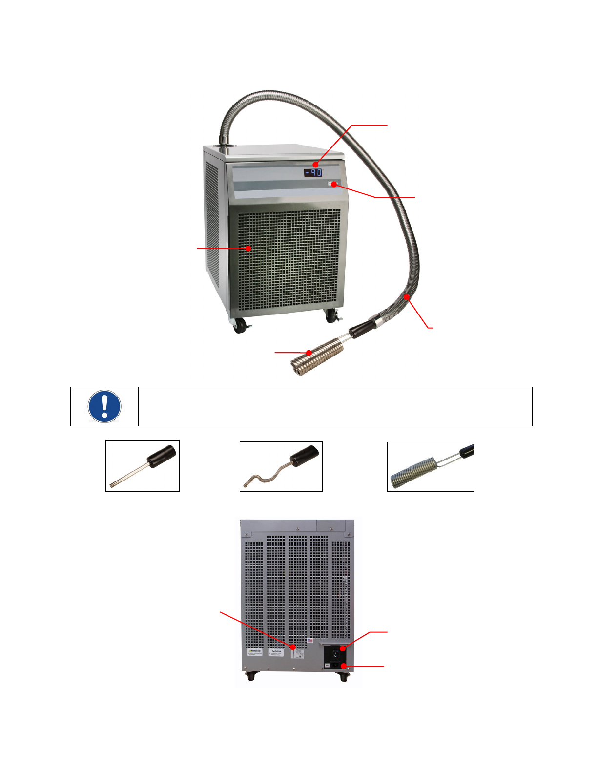
Controls & Components......................................................................................................................................... 5
Quick-Start ............................................................................................................................................................ 6
Installation & Startup ............................................................................................................................................ 7
General Site Requirements.......................................................................................................................... 7
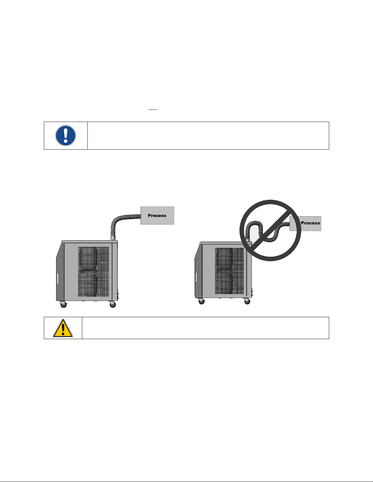
Positioning the Immersion Probe Assembly .................................................................................................. 7
Electrical Power.......................................................................................................................................... 8
Normal Operation.................................................................................................................................................. 8
Turning Your Immersion Probe Cooler ON .................................................................................................... 8
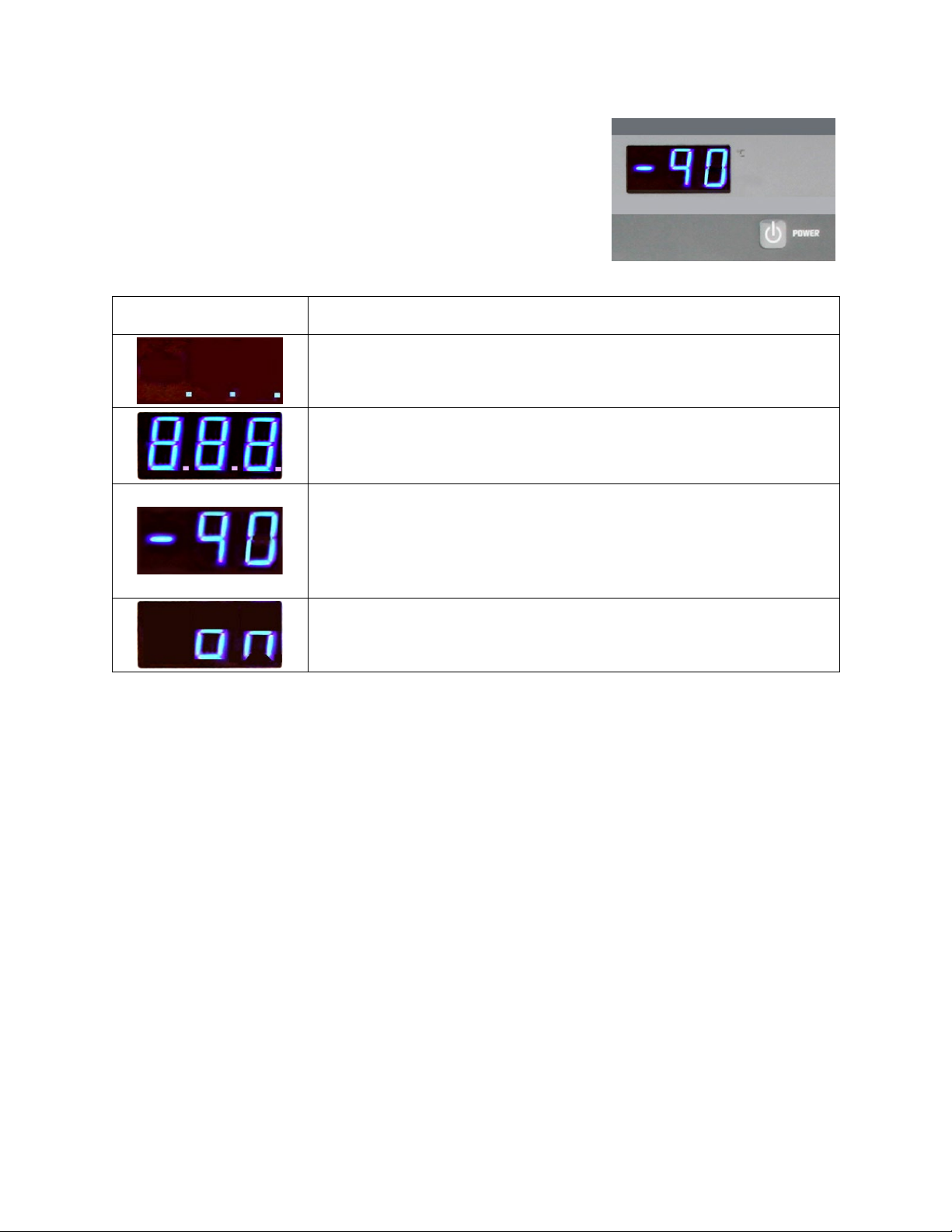
Main Operational Display............................................................................................................................ 9
Display Messages ....................................................................................................................................... 9
Loss of Power Restart ................................................................................................................................. 9
Routine Maintenance & Troubleshooting ............................................................................................................ 10
Cleaning Exterior Surfaces ......................................................................................................................... 10
Cleaning the Air Filter ............................................................................................................................... 10
Draining Residual Oil from the Immersion Probe Assembly .......................................................................... 10
Troubleshooting ....................................................................................................................................... 11
Technical Information.......................................................................................................................................... 12
Performance Specifications ....................................................................................................................... 12
Equipment Disposal (WEEE Directive).................................................................................................................. 13
Service & Technical Support ................................................................................................................................ 13
Warranty ............................................................................................................................................................. 14

2
Introduction
Your Immersion Probe Cooler can be used to achieve low-temperature capability with non-refrigerated circulating
baths or boost the cooling capacity of refrigerated circulators. It is also excellent for trapping and Dewar-type
applications, making it an economical alternative to dry ice or liquid nitrogen. A 6-ft. (1.83 m) flexible hose allows
convenient placement of the cooling probe.
It will take you very little time to get your Immersion Probe Cooler installed and running. This operator’s manual is
designed to guide you quickly through the process. We recommend that you read it thoroughly before you begin.
NOTE: The Immersion Probe Cooler operates at maximum cooling performance. Maximum temperature
stability will be achieved in an agitated fluid and with a constant heat load. Allow ample time to reach the
lowest achievable temperature.
General Information
General Safety Information
When installed, operated, and maintained according to the directions in this manual and common safety
procedures, your Immerson Probe Cooler should provide safe and reliable cooling. Please ensure that all
individuals involved in the installation, operation, or maintenance of this unit read this manual thoroughly prior to
working with the unit.
This symbol marks chapters and sections of this instruction manual that are particularly relevant to safety.
When attached to the unit, this symbol draws attention to the relevant section of the instruction manual.
This symbol advises you of danger from electricity or electric shock.
This symbol marks information that is particularly important.
This symbol indicates alternating current.
/
These symbols on the Power Switch / Circuit Breaker indicate that they place the main power supply ON /
OFF.
This symbol on the Power Key indicates that it places the unit in a standby mode. It DOES NOT fully
disconnect the unit from the power supply.
This symbol indicates a protective conductor terminal.
Read all instructions pertaining to safety, set-up, and operation.
Proper operation and maintenance is the user’s responsibility.

3
Safety Recommendations
To prevent injury to personnel and/or damage to property, always follow your workplace’s safety procedures
when operating this equipment. You should also comply with the following safety recommendations:
WARNING:
• Always connect the power cord on this unit to a grounded (3-prong) power outlet. Make certain that the
outlet is the same voltage and frequency as your unit.
• Never operate the unit with a damaged power cord.
• Always turn the unit OFF and disconnect Mains power before performing any maintenance or service.
WARNING:
• Never touch the immersion probe assembly while the unit is operating.
• Always allow the immersion probe to warm to ambient temperature before repositioning or working on the
unit.
• Do not move the immersion probe assembly while the unit is operating.
Unpacking Your Immersion Probe Cooler
Your Immersion Probe Cooler was packed in a special carton. You should keep the packaging, along with all packing
materials, until the unit has been installed and you are certain it is working properly.
CAUTION:Remove any loose packing material that may have clung to the base or wand assembly.
WARNING:Keep unit upright when moving. Be sure to follow your company’s procedures and practices
regarding the safe lifting and relocation of heavy objects.
In the unlikely event that the unit was damaged or does not operate properly, contact the company where your
Immersion Probe Cooler was purchased.

4
Regulatory Compliance & Testing
cCSAus (120V, 60Hz units)
UL 61010-1 (3rd Edition) - Safety Requirements for Electrical Equipment for Measurement, Control, and
Laboratory Use - Part 1: General Requirements
CAN/CSA-C22.2 No 61010-1-12 - Safety Requirements for Electrical Equipment for Measurement, Control, and
Laboratory Use - Part 1: General Requirements
Product meets CAN ICES-1/NMB-1 and FCC Part 15
This device complies with part 15 of the FCC rules. Operation is subject to the following two conditions: 1. This
device may not cause harmful interference, and 2. This device must accept any interference received, including
interference that may cause undesired operation.
IEC/CE (230V, 50Hz units; 100V, 50/60Hz units)
Machinery Directive 2006/42/EC Annex I
IEC 61010-1:2010 - Safety Requirements for Electrical Equipment for Measurement, Control, and Laboratory
Use - Part 1: General Requirements
EN 61010-1:2010 - Safety Requirements for Electrical Equipment for Measurement, Control, and Laboratory Use
- Part 1: General Requirements
EMC Directive 2014/30/EU
EN 61326-1:2013 - Electrical Equipment for Measurement, Control and Laboratory Use - EMC Requirements -
Part 1: General Requirements
RoHS Directive 2011/65/EU
EN 50581:2012 - Technical Documentation for The Assessment of Electrical and Electronic Products With
Respect to The Restriction of Hazardous Substances
Highly Accelerated Life Test (HALT) and Vibration Tests per ASTM D4169-8 (All units)
Contents
The Following Items Have Been Included With Your Immersion Probe Cooler:
• Operator’s Manual
• IEC Electrical Cord
• Certificate of Compliance

5
Controls & Components
IMPORTANT: The temperature display is for reference only. The actual temperature of the immersion
probe will be colder than the displayed temperature.
Cold Finger Immersion Probe Flexible Immersion Probe 1.75” Rigid Coil Probe
Power Key
Temperature Display
Air Filter
Compartment
Power Switch /
Circuit Breaker
IEC Electrical Connection
Rigid Coil Immersion Probe
(3” rigid coil shown)
Identification Label
Immersion Probe
Assembly

6
Quick-Start
1 Position Immersion Probe
2 Connect power. See
Identification Label.
3 Turn main power ON.
4
Turn Standby power ON.
Allow approximately 10
minutes for the system to
begin the cooling process.
5
Allow approximately 1 hour
for system to reach
-80°C (IP-80) or
-90°C (IP-100).
(typical)
CAUTION: Moving Immersion Probe Cooler while unit is operating may result in damage.

7
Installation & Startup
Your Immersion Probe Cooler is designed to be simple to set-up and install. No tools are required.
General Site Requirements
Locate the unit on a level surface, free from drafts and out of direct sunlight. Do not place it where there are
corrosive fumes, excessive moisture, high room temperatures, or where excessive dust is present.
The unit must be a minimum of 6 inches / 15.24 cm away from walls or vertical surfaces so that airflow
around the unit is not restricted. It should not be placed in cabinets or where exiting warm air or warm air
from other devices will be drawn into the air intake on the front of the unit.
NOTE: It is recommended that your unit be run in ambient temperatures below 95°F / 35°C. While the
unit will operate at higher ambient temperatures, it may not be able to achieve maximum cooling
performance.
Positioning the Immersion Probe Assembly
When installing the unit, make sure that the Immersion Probe Assembly is properly positioned. It should not
be twisted. Incorrect positioning of the Wand Assembly will cause your Immersion Probe Cooler to perform
below specifications.
CAUTION: Moving the Immersion Probe Assembly while the unit is operating may result in damage.

8
Electrical Power
WARNING: IMPORTANT INFORMATION FOR 100V APPLICATIONS
On 100V 50Hz applications a step-up transformer IS NOT NEEDED and MUST NOT be used.
On 100V 60Hz applications a step-up transformer MUST be used.
WARNING: Make certain that the electrical outlet is the same voltage and frequency as your unit. The correct
voltage and frequency for your unit are indicated on the Identification Label on the back panel.
WARNING:The use of an extension cord is not recommended. If one is necessary, it must be properly
grounded and capable of handling the total wattage of the unit. The extension cord must not cause more than
a 10% drop in voltage to the unit.
Attach the 6-ft / 1.8 m power cord to the IEC electrical connector on the back of the unit and then plug the male
connector into the Mains electrical outlet.
Place the Power Switch / Circuit Breaker on the back of the Immersion Probe
Cooler in the ON position. Three decimal points will appear on the
Temperature Display. This indicates that the unit is in Standby mode.
Your Immersion Probe Cooler is now ready to begin normal operation.
Normal Operation
Turning Your Immersion Probe Cooler ON
Press the Power Key on the front panel. After a brief initialization message,
the probe temperature will appear on the Temperature Display. After five
minutes, the first stage compressor and fan will turn on to begin the cooling
process. During this start-up phase, the displayed temperature will remain
near or at ambient temperature.
After approximately 10 minutes, the second stage compressor will turn on,
refrigerant will begin circulating through the system, and the displayed
temperature will begin decreasing. It generally takes approximately 60 minutes from power up for the IP-80 to
reach -80°C or for the IP-100 to reach -90°C.
NOTE: The Immersion Probe Cooler operates at maximum cooling performance.
IMPORTANT: To protect its compressors from damage, the Immersion Probe Cooler incorporates a
special safety switch that delays compressor startup for 10 minutes whenever power is applied. This 10
minute delay will occur even when power is only momentarily disrupted.

9
Main Operational Display
The actual temperature of the immersion probe is displayed in degrees C on
the unit’s digital readout. Due to the location of the temperature sensor, this
temperature is a few degrees warmer than the surface temperature of the
immersion probe.
Display Messages
Temperature Display Description
Standby Mode — Indicates that the Power Switch / Circuit Breaker on the back
panel is in the ON position and unit is ready to operate.
Power On / Start-Up — Appears briefly when the Immersion Probe Cooler is
turned ON by pressing the Power Key on the front panel. The information
represents the firmware version.
Main Operational Display — Indicates unit is ON and operating. Displayed
temperature is in degrees C.
Note: Displayed temperature is to one tenth of a degree (X..X) until it reaches -
10°.
Warning Display — Indicates that the external temperature sensor is not
functioning properly. Unit will continue to cool.
Loss of Power Restart
In the event that electrical power is disrupted during operation, the unit will begin operating automatically when
power is restored. As with normal start-up, it will take approximately 60 minutes for the IP-80 to reach -80°C or the
IP-100 to reach -90°C.

10
Routine Maintenance & Troubleshooting
Cleaning Exterior Surfaces
Only mild detergents and water or an approved cleaner should be used on the painted surfaces of the Immersion
Probe Cooler. Do not allow cleaning liquids or sprays to come in direct contact with the digital display.
Cleaning the Air Filter
To keep the refrigeration system operating at optimum cooling capacity, the front and back
air vents and reusable filter should be kept free of dust and dirt. They should be checked on
a scheduled basis and cleaned as required.
The reusable filter is easily accessed by simply sliding it out of the side of the front grill. Use a
mild detergent and water solution to wash off any accumulated dust and dirt and then rinse
and dry thoroughly before reinstalling.
Draining Residual Oil from the Immersion Probe Assembly
A thin film of oil may build up within the Immersion Probe Assembly with extended use and adversely affect the
unit’s cooling efficiency. To ensure maximum cooling performance, we recommend that this oil be drained from
the Immersion Probe Assembly after every 200 hours of use or whenever you see a drop in cooling performance.
1. Place the Immersion Probe Cooler in the Standby mode by pressing the Power Key on the front panel.
2. Elevate the Immersion Probe Assembly as high as possible above the unit’s enclosure for 10 to 15 minutes
to allow residual oil to drain back into the compressor. Do not allow the assembly to twist or dip as oil
may pool internally in these areas.
CAUTION: Moving Immersion Probe Assembly while unit is operating may result in damage.
CAUTION: Should you experience frequent drops in cooling performance due to the accumulation of oil in
the Immersion Probe Assembly, verify that it is properly installed, without any twists. See Positioning the
Immersion Probe Assembly under Installation & Startup.

11
Troubleshooting
WARNING:Always turn the Power Switch / Circuit Breaker OFF and disconnect the electrical cord from the
power source before servicing the unit.
Problem Cause Corrective Action
Unit does not run
(Temperature Display is
blank)
No power to unit
Power Switch / Circuit Breaker in
OFF position
Check that electrical cord is secure and plugged into an
operating electrical outlet.
Place Power Switch / Circuit Breaker in ON position.
Unit does not run
(Three decimals on
Temperature Display)
Unit in Standby mode Press Power Key on front panel.
Unit does not run
(Temperature Display
reading increasing or at
ambient)
Compressor overload switch has
tripped
Allow approximately 10 minutes for unit to restart.
Check air filter and air vents for blockages.
Check that airflow around unit is not restricted and that
room temperatures does not exceed 95°F / 35°C.
Check compressor fan for operation (listen for fan noise,
check for airflow through unit).
No or insufficient
cooling
Blocked air flow
High ambient temperature
Oil in Immersion Probe Assembly
Improper line voltage and/or
frequency
Check air filter and air vents for blockages.
Check that airflow around unit is not restricted and that
room temperatures does not exceed 95°F / 35°C.
Drain oil from Immersion Probe Assembly.
Verify that Mains voltage during start cycle is within 10% of
rated voltage.
Gradual loss of cooling
Blocked air flow
High ambient temperature
Oil in Immersion Probe Assembly
Check air filter and air vents for blockages.
Check that airflow around unit is not restricted and that
room temperatures does not exceed 95°F / 35°C.
Drain oil from Immersion Probe Assembly.
Compressor shakes,
stalls, or continually
restarts
Compressor cycling or
overloaded
Check air filter and air vents for blockages.
Check that airflow around unit is not restricted and that
room temperatures does not exceed 95°F / 35°C.
Verify that Mains voltage during start cycle is within 10% of
rated voltage.
Check compressor fan for operation (listen for fan noise,
check for airflow through unit).

12
Technical Information
Performance Specifications
Model IP-80 IP-100
Temperature Range -80° to -40°C -100° to -60°C
Temperature Set Point Fixed at -80°C Fixed at -100°C
Readout Accuracy ±1.0°C
Compressors Two nominal ½ HP low back pressure reciprocating compressors
Cooling Probe Assembly 6 ft. / 1.83 m flexible hose
Cooling Probe Rigid Coil
1.75 in. / 4.44 cm diameter;
7.0 in. / 17.8 cm length
Rigid Coil
3 in. / 7.62 cm diameter;
9.0 in. / 22.9 cm length
Rigid Cold Finger
0.75 in. / 1.91 cm diameter;
3.75 in. / 9.53 cm length
Flexible Cold Finger
0.625 in. / 1.59 cm diameter;
15 in. / 38.1 cm length
Dimensions (H x W x D) 21 x 15 x 20.125 in. / 53.34 x 38.1 x 51.12 cm
Electrical Requirements: 120V, 60Hz, 12A
230V, 50Hz, 7.5A
100V, 50Hz, 12A
100V, 60Hz, 12A (step-up transformer required)
Environmental Conditions: For indoor use only
Maximum altitude: 6562 ft. / 2000 m
Relative humidity: 80% for temperatures up to 95°F / 35°C
Over voltage: ±10%
Nominal ambient: 68°F / 20°C
Maximum recommended operating ambient: 95°F / 35°C
Installation Category II
Pollution Degree 2
WARNING: IMPORTANT INFORMATION FOR 100V APPLICATIONS
On 100V 50Hz applications a step-up transformer IS NOT NEEDED and MUST NOT be used.
On 100V 60Hz applications a step-up transformer MUST be used.

13
Equipment Disposal (WEEE Directive)
or
This equipment is marked with the crossed out wheeled bin symbol to indicate it is covered by the Waste Electrical
and Electronic Equipment (WEEE) Directive and is not to be disposed of as unsorted municipal waste. Any products
marked with this symbol must be collected separately, according to the regulatory guidelines in your area.
It is your responsibility to correctly dispose of this equipment at lifecycle-end by handing it over to an authorized
facility for separate collection and recycling. It is also your responsibility to decontaminate the equipment in case
of biological, chemical and/or radiological contamination, so as to protect the persons involved in the disposal and
recycling of the equipment from health hazards. By doing so, you will help to conserve natural and environmental
resources and you will ensure that your equipment is recycled in a manner that protects human health.
Requirements for waste collection, reuse, recycling, and recovery programs vary by regulatory authority at your
location. Contact your local responsible body (e.g., your laboratory manager) or authorized representative for
information regarding applicable disposal regulations.
Service & Technical Support
If you have followed the troubleshooting steps and your Immersion Probe Cooler fails to operate properly, contact
the distributor or manufacturer from whom the unit was purchased. Have the following information available for
the customer service person.
• Model, Serial Number, and Voltage (from back panel)
• Date of purchase and your purchase order number
• Suppliers' order number or invoice number
• A summary of your problem

14
Warranty
The manufacturer agrees to correct for the original user of the product, either by repair (using new or refurbished
parts), or at the manufacturer’s election, by replacement (with a new or refurbished product), any defects in
material or workmanship which develop during the warranty period. The standard warranty is twenty-four (24)
months after delivery of the product. In the event of replacement, the replacement unit will be warranted for the
remainder of the original warranty period or ninety (90) days, whichever is longer. For purposes of this limited
warranty, “refurbished” means a product or part that has been returned to its original specifications. In the event
of a defect, these are your exclusive remedies.
If the product should require service, contact the manufacturer’s/supplier’s office for instructions. When return of
the product is necessary, a return authorization number is assigned and the product should be shipped,
transportation charges pre-paid, in either its original packaging or packaging affording an equal degree of
protection to the indicated service center. To insure prompt handling, the return authorization number must be
placed on the outside of the package. A detailed explanation of the defect should be enclosed with the item.
The warranty shall not apply if the defect or malfunction was caused by accident, neglect, unreasonable use,
improper service, acts of God, modification by any party other than PolyScience, or other causes not arising out of
defects in material or workmanship.
EXCLUSION OF IMPLIED WARRANTIES. THERE ARE NO WARRANTIES, EXPRESSED OR IMPLIED, INCLUDING, BUT
NOT LIMITED TO, THOSE OF MERCHANTABILITY OR FITNESS FOR A PARTICULAR PURPOSE WHICH EXTEND BEYOND
THE DESCRIPTION AND PERIOD AS STATED IN THE OPERATOR’S MANUAL INCLUDED WITH EACH PRODUCT.
LIMITATION ON DAMAGES. THE MANUFACTURER’S SOLE OBLIGATION UNDER THE WARRANTY IS LIMITED TO THE
REPAIR OR REPLACEMENT OF A DEFECTIVE PRODUCT AND POLYSCIENCE SHALL NOT, IN ANY EVENT, BE LIABLE FOR
ANY INCIDENTAL OR CONSEQUENTIAL DAMAGES OF ANY KIND RESULTING FROM USE OR POSSESSION OF THIS
PRODUCT.
Some states do not allow: (A) limitations on how long an implied warranty lasts; or (B) the exclusion or limitation
of incidental or consequential damages, so the above limitations or exclusions may not apply to you. This warranty
gives you specific legal rights and you may have other rights that vary from state to state.
Cole
-Parmer
625 East Bunker Ct.,
Vernon Hills, IL 60061
US
1065Y105_M_IP
-400_IP_MAN_Rev_1023
This manual suits for next models
2
Table of contents
Other Cole Parmer Chiller manuals
Popular Chiller manuals by other brands

Daikin
Daikin EWAA011DAV3P User reference guide

Carrier
Carrier Aquaforce 30XA Series Operation instructions

SMC Networks
SMC Networks HRS090-A...-20 Series Original instructions

Across International
Across International C20 user manual

Unical
Unical SLIM HP 2.0 manual

Trane
Trane CVHE installation instructions

Carrier
Carrier AquaEdge 19XR Start-up, operation and maintenance instructions

Samsung
Samsung AG042KSV Series installation manual

CLIVET
CLIVET WSAT-YSC4 manual

Lauda
Lauda MC 250 Operation instructions

Zanussi
Zanussi ZANUSSI easyChill BCFW061 Brochure & specs

Aqua Optima
Aqua Optima Corona Instructions for use