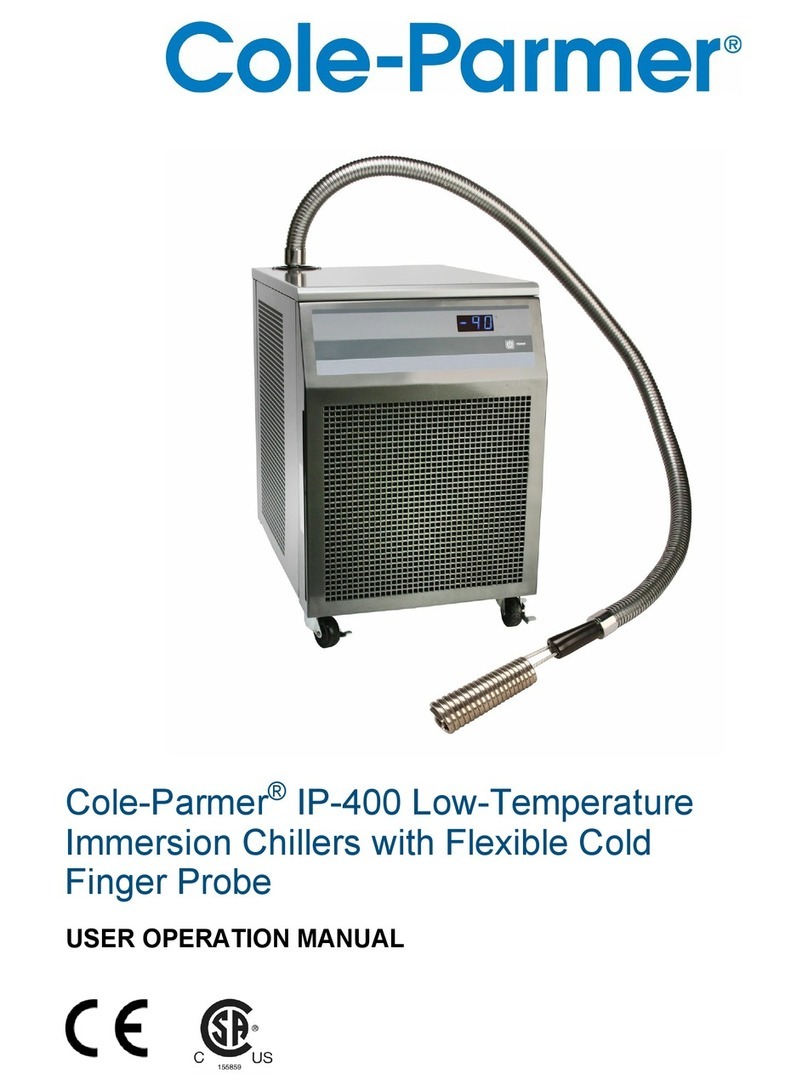
Cole Parmer Polystat I Owner's manual

Installation
Operation
Basic Maintenance
High Capacity
Recirculating Chillers
Manual P/N U01177 Rev. 04/04/2012
Label


Polystat
Cole Parmer
Contents
Quick Starts
Preface .................................................................................................................................i
Compliance..............................................................................................................i
WEEE .....................................................................................................................i
Warranty ..................................................................................................................ii
Unpacking...............................................................................................................ii
Section 1 Safety ..................................................................................1-1
Warnings..............................................................................................................1-1
Element Assessment .........................................................................................1-3
Personal Protective Equipment.......................................................................1-3
Training................................................................................................................1-3
Section 2 General Information .............................................................2-1
Description .........................................................................................................2-1
Intended Use ......................................................................................................2-1
Specications......................................................................................................2-1
Equipment Ratings............................................................................................2-8
Sample Nameplate.............................................................................................2-9
Approved Fluids.................................................................................................2-9
Wetted Materials.................................................................................................2-9
Section 3 Installation ...........................................................................3-1
Ventilation...........................................................................................................3-1
Electrical Requirements ....................................................................................3-1
Plumbing Requirements....................................................................................3-2
Process Fluid Requirements.............................................................................3-3
Compatibility with Approved Fluids ..............................................................3-4
Process Water Quality and Standards.............................................................3-5
Filling ..................................................................................................................3-6
Water Treatment Kit..........................................................................................3-7
Section 4 Operation .........................................................................................................4-1
Controller............................................................................................................4-1
Start Up/Shut Down.........................................................................................4-2
Circuit Protector ................................................................................................4-2
Start Up ...............................................................................................................4-2
Setpoint................................................................................................................4-2
Temperature Alarm ...........................................................................................4-3
Setup/Tune Loop ..............................................................................................4-4
Stopping ..............................................................................................................4-6
Draining...............................................................................................................4-6
Storage.................................................................................................................4-6
Disposal/Decommissioning ............................................................................4-7

Polystat
Contents
Cole Parmer
Section 5 Preventive Maintenance............................................................................... 5-1
Cleaning...............................................................................................................5-1
Condenser...........................................................................................................5-1
Fluid Maintenance .............................................................................................5-1
Reservoir .............................................................................................................5-1
Pump Strainer.....................................................................................................5-2
Hoses ..................................................................................................................5-2
Temperature Sensor (rdt1) Calibration...........................................................5-3
Section 6 Troubleshooting .....................................................................6-1
Error Codes........................................................................................................6-1
Checklist..............................................................................................................6-2
Controller PID Values.......................................................................................6-3
Displaying Software Version............................................................................6-4
Flow Diagram
Declaration of Conformity

Process Outlet
1/2" FNPT Brass
J1 Serial Communications
(Optional)
Circuit Protector
Power Inlet
Process Inlet
1/2" FNPT Brass
DRAIN
1Connect the PROCESS OUTLET to the
uid inlet on your application. Connect the PROCESS
INLET to the uid outlet on your application.
Ensure all connections are secure and that the proper
sealant/lubricant for the tting material is used. (If
Teon® tape is used, ensure the tape does not overhang
the rst thread as it could shred and get into the uid.)
Acceptable uids are:
Filtered/Single Distilled water•
0 - 75% Ethylene Glycol/Water•
0 - 75% Propylene Glycol/Water•
Deionizedwater(1-3MΩ-cm,compensated)•
Safety Precautions:
The unit is designed for indoor use only.
Neverplaceunitinalocationwhereexcessiveheat,moisture,inadequateventilation,
orcorrosivematerialsarepresent.
Neveruseammableorcorrosiveuidswiththisunit.
Neverconnectprocessuidlinestoyourfacilitywatersupplyortoanypressurized
liquidsource.
Ifyourunitisequippedwithapositivedisplacementpump(PD1orPD2),ensureyour
applicationplumbinglinesandttingsareratedtowithstandaminimumof115psi.
Beforeusinganyuidorperformingmaintenancewherecontactwiththeuidislikely
refertothemanufacturer’sMSDSforhandlingprecautions.
2 Ensure the reservoir drain plug on the back of the
unit is in place and that all plumbing connections are secure.
Loosen the two thumbscrews securing the reservoir cover
to the unit. Ensure the uid lter is securely in place in
the bottom of the reservoir. Slowly ll the unit with clean
process uid until the uid reaches the reservoir's lip.
Since the reservoir capacity may be small compared to your
application and air may need to be purged from the lines,
have extra cooling uid on hand to keep the system topped
off when external circulation is started. Failure to keep the
reservoir full to the lip will result in loss of cooling capacity.
Replace the reservoir cover and tighten the thumbscrews.
The lid must remain secure to minimize evaporation and
keep debris out of the reservoir.
Quick Start Guide
Thumbscrews
Reservoir Lip
Page1of2
3Verify the appropriate voltage. Insert female end of
power cord into the chiller power inlet and then insert male
end of power cord into a power outlet.
4Place the circuit protector to the up position, the
controller will ash and the alarm will momentarily sound.
See next page.
1
2
3
4

Press . The controller will do a self-test (the controller will quickly sequence through its LEDs and
momentarily sound the alarm) and then display the recirculating uid temperature. The refrigeration system and
the recirculation pump will then start. The RECIRCULATING PRESSURE gauge will display the pump operating
pressure. If the pressure needs adjusting, refer to Section 3 in the manual.
NOTE If on start up the unit's recirculating uid is outside either temperature limit, the unit will operate but the
appropriate indicator will ash until the uid is within the limit.
To display/change the setpoint use the arrow keys, will illuminate.
NOTE If the arrow keys are not pressed within 10 seconds the display will return to the current reservoir
temperature. The controller will not allow you to enter a setpoint closer than 2°C of either temperature alarm
setting. Trying to use a setpoint within 2°C causes the appropriate indicator to ash and sounds the audible alarm
twice.
Once the desired setpoint is displayed, press to conrm the change. The display will rapidly ash the new value
for a short period and then return to the recirculating uid temperature.
Use this key to
toggle the unit on
or off.
Indicates refrigeration system status.
Indicates the
controller is displaying
the setpoint. Press the
arrow keys to change
the value.
Pressure Gauge
Indicates the controller is
displaying the unit's low
temperature alarm setting.
Indicates the controller is
displaying the high temperature
alarm setting.
Optional. Indicates the unit
is operating in the serial
communication mode.
Press to change the
displayed value.
Press to sequence through the
four indicators and accept the
displayed value.
5
Page 2 of 2

Polystat i
Cole Parmer
Preface
Compliance European Union ( EU ) LVD & EMC
Our evaluation has demonstrated compliance with the following EU
directives, as indicated by the CE Mark located on the chiller nameplate
and the Declaration of Conformity in the back of this manual.
2004/108/EC - Electromagnetic Compatibility Directive (EMC):
EN61326-1:2006 - Electrical equipment for measurement, control, and
laboratory use - EMC requirements
2006/95/EC - Low Voltage Directive (LVD):
EN61010-1:2001 - Safety requirements for electrical equipment for
measurement, control, and laboratory use - general requirements
WEEE This product is required to comply with the European Union’s Waste
Electrical & Electronic Equipment (WEEE) Directive 2002/96/EC. It is
marked with the following symbol:

ii Polystat
Preface
Cole Parmer
Warranty Cole-Parmer warrants to the direct purchaser that the Cole-Parmer Polystat
recirculating chillers, distributed by Cole-Parmer, will be free from defects
in material or workmanship for a period of one year from the date of
delivery.
Cole-Parmer will repair or replace the product or provide credit, as its sole
option, upon prompt notication and compliance with its instructions.
The Distributor warrants to Customer that upon prompt notication and
compliance with Distributor's instructions, that the Distributor will repair
or replace, at Distributor's sole option, any Product which is defective in
material or workmanship.
Distributor expressly disclaims all other warranties, whether expressed,
implied or statutory, including the warranties of merchantability, and
tness for a particular purpose. Distributor's sole responsibility and the
Customer's exclusive remedy for any claim arising out of the purchase
of any Product is repair or replacement, as described above. In no event
shall Distributor's liability exceed the purchase price pain therefor; nor
shall Distributor be liable for any claims, losses or damage of any third
party or for lost prots or any special, indirect, incidental, consequential,
or exemplary damages, howsoever arising, even if Distributor has been
advised of the possibility of such damages.
The line cord it is located under the shipping crate’s lid. Do not discard the
lid until the cord is located.
Retain all cartons and packing material until the chiller is operated and
found to be in good condition. If the chiller shows external or internal
damage contact the transportation company and le a damage claim. Under
ICC regulations, this is your responsibility.
Out of Box Failure
An Out of Box Failure is dened as any product that fails to operate in
conformance with sellers published specications at initial power up. Install
the chiller in accordance with manufacturer's recommended operating
conditions within 30 days of shipment from the seller.
Any Temperature Control product meeting the denition of an Out of
Box Failure must be packed and shipped back in the original packaging
for replacement with a new chiller; seller to pay the cost of shipping.
Customer must receive a Return Material Authorization (RMA) from prior
to shipping.
Unpacking

Cole Parmer Polystat 1-1
Make sure you read and understand all instructions and safety precautions
listed in this manual before installing or operating your chiller. If you have
any questions concerning the operation of your chiller or the information
in this manual, please contact us. See inside cover for contact information.
DANGER indicates an imminently hazardous situation which, if not
avoided, will result in death or serious injury.
WARNING indicates a potentially hazardous situation which, if not
avoided, could result in death or serious injury.
CAUTION indicates a potentially hazardous situation which, if not
avoided, may result in minor or moderate injury. It is also be used to alert
against unsafe practices.
The lightning ash with arrow symbol, within an equilateral triangle, is
intended to alert the user to the presence of non-insulated "dangerous
voltage" within the chiller's enclosure. The voltage magnitude is signicant
enough to constitute a risk of electrical shock.
This label indicates read the manual.
NOTE The chiller's equipment design incorporates a complete sheet metal
enclosure for personnel protection from mechanical and electrical hazards.
Observe all warning labels.
Never remove warning labels.
The chiller construction provides protection against the risk
of electrical shock by grounding appropriate metal parts. The
protection will not function unless the power cord is connected to a
properly grounded outlet. It is the user's responsibility to assure a
proper ground connection is provided.
The circuit protector located on the rear of the chiller is not intended
to act as a disconnecting means.
If the chiller's power cord is used as the disconnecting device, it
must be easily accessible at all times.
Never operate the chiller with damaged cords.
Never place the chiller in a location or atmosphere where excessive
heat, moisture, or corrosive materials are present.
Safety Warnings
Section 1 Safety
DANGER
WARNING
CAUTION

1-2 Polystat
Section 1
Cole Parmer
Many refrigerants which may be undetectable by human senses are heavier than air and will
replace the oxygen in an enclosed area causing loss of consciousness. Refer to the chiller's
nameplate and the manufacturer's most current MSDS for additional information.
Never connect the process uid inlet or outlet ttings to your building water supply or
any water pressure source.
Never operate the chiller without uid in the reservoir.
Other than water, before using any uid, or when performing maintenance where contact
with the uid is likely, refer to the manufacturer’s MSDS and EC Safety Data sheet for
handling precautions.
Ensure, that no toxic gases can be generated by the uid. Flammable gases can build up
over the uid during usage.
Do not use automotive antifreeze. Commercial antifreeze contains silicates, or any
Organic Acid Technologies (OATs), that can damage the pump seals. Use of automotive
antifreeze will void the manufacturer’s warranty.
Never use corrosive or ammable uids with this chiller. Use of these uids will also void
the manufacturer’s warranty.
When using a process uid mixture of ethylene glycol and water or propylene glycol and
water, check the uid concentration and pH on a regular basis. Changes in concentration
and pH can impact system performance. See Section 3.
Never operate damaged or leaking equipment.
Never operate the chiller or add uid to the reservoir with panels removed.
Do not clean the chiller with solvents, only use a soft cloth and water.
Drain the chiller before it is transported and/or stored in, near or below freezing
temperatures. Store the chiller in the temperature range -25°C to 60°C (with packaging),
and <80% relative humidity.
Always turn the chiller off and disconnect the supply voltage from its power source
before moving the chiller or before performing any service or maintenance procedures.
Transport the chiller with care. Sudden jolts or drops can damage its components.
Refer service and repairs to a qualied technician.
Performance of installation, operation, or maintenance procedures other than
those described in this manual may result in a hazardous situation and will void the
manufacturer's warranty.

Preface
Polystat 1-3
Cole Parmer
Element Assessment
Personal Protective Equipment
Training
The are no special personal protective equipment requirements needed to perform normal operation. We do
recommend wearing eye protection.
The user must review and understand all the sections in this manual before operating the chiller.
Chemical Used —
R134A Refrigerant - CFC Free Lubricating Oil: Polyol Ester Oil and Syno Ad
Amount: Polystat I and II 0.62 ounces, Amount: I and II 283 cc, III 282 cc
Polystat III 1.07 ounces Location: Refrigeration system
Location: Compressor
Hazard Communication — None
Electrical — All electrical energy sources for the chiller are provided by the user.
Hazardous Energy Isolation — Locate energy isolation devices in a location that is readily accessible.
Electrical Remove power from the chiller by turning the circuit protector off and disconnecting the line
cord, see Section 3 Electrical Requirements.
Fluid Before using any uid refer to the manufacturer’s MSDS and EC safety data sheets for handling
precautions. The user is responsible to ensure the reservoir overow located on the rear of the chiller is
connected to a suitable drain.
Refrigeration The chiller's refrigeration system is sealed and requires no lockout/tagout.
Remove any isolation devices before starting the chiller.
Chemicals — Prior to decontamination procedures should be developed and employed to minimize or
mitigate opportunities for exposure to chemicals present in or around the chiller.
Radioactive Material — None
Magnetic Fields — None
Sampling and Analysis for External Contaminants from Other Sources or from Spill Events It is the
responsibility of the user to identify the presence of all external chemicals before the decontamination.
This should be accomplished by collecting samples and analyzing them for any suspected chemicals used
or stored in areas adjacent to the chiller.
Oxygen Deciency — Many refrigerants which may be undetectable by human senses are heavier than
air and will replace the oxygen in an enclosed area causing loss of consciousness. Refer to the chiller's
nameplate and the manufacturer's most current MSDS for additional information. Test the atmosphere
in a conned space area or area where gases are being used to purge the chiller. If necessary, use an air
supplied respirator.

1-4 Polystat
Section 1
Cole Parmer

Polystat 2-1
Cole Parmer
Cooling capacity based on• PD 1pump with no backpressure. Heat input from the pump will
result in a reduction in cooling capacity. The cooling capacity reduction will vary based on the
pump chosen as well as pump backpressure and flow. 60 Hz chillers.
Specifications obtained at sea level using water as the recirculating fluid, at a 20°C process•
setpoint, 20°C ambient condition, at nominal operating voltage. Other fluids, fluid temperatures,
ambient temperatures, altitude or operating voltages will affect performance. See Section 3.
Keep the reservoir full at all times. Low fluid levels will result in loss of cooling capacity if the•
fluid level is allowed to drop below the cooling coils.
Cole Parmer reserves the right to change specifications without notice.•
Section 2 General Information
The Cole Parmer Polystat recirculating chiller is designed to provide
a continuous supply of uid at a constant temperature and ow rate.
The chiller consists of an air-cooled refrigeration system, reservoir
tank evaporator coil, recirculating pump, polyethylene reservoir, and a
microprocessor controller.
It is designed for continuous operation and for indoor use in accordance with
all the procedures and requirements stated in this manual.
Specifications
* 60 Hz units. The MD pump is only available in 12911-12, 14. Pumping capacity pressure values
are differential pressures between the inlet and the outlet of the unit.
Cole Parmer Catalog Number
Polystat I Polystat II Polystat III
Process Fluid Temperature -10°C to +30°C -10°C to +30°C -10°C to +30°C
and Setpoint Range +14°F to +86°F +14°F to +86°F +14°F to +86°F
Ambient Temperature Range +10°C to +35°C +10°C to +35°C +10°C to +35°C
+50°F to +95°F +50°F to +95°F +50°F to +95°F
Temperature Stability ±0.1°C ±0.1°C ±0.5°C
Cooling Capacity at 20°C 700 W (2391 BTU) 1000 W (3415 BTU) 2000 W (6830 BTU)
Reservoir Volume Gallons 2.0 2.0 5.0
Liters 7.6 7.6 18.9
Footprint or Dimensions (L xWxH)
Inches 14 x 23 3/4 x 23 14 x 23 3/4 x 23 17 x 28 x 23
Centimeters 35.6 x 60.3 x 58.4 35.6 x 60.3 x 58.4 43.2 x 71.1 x 58.4
Weight PD 1 Pump (empty) ±5.0 lb 90.0 90.0 160.0
±2.2 kg 40.8 40.8 72.6
Pumping Capacity*
PD 1 - Positive Displacement 1.4 gpm @ 60 psid (5.3 lpm @ 4.1 bar) - Catalog #12911 - 00, 04, 16
PD 2 - Positive Displacement 3.6 gpm @ 60 psid (13.6 lpm @ 4.1 bar) - Catalog #12911 - 08, 20
MD - Magnetic Drive 2.0 gpm @ 10 psid (7.6 lpm @ 0.7 bar) - Catalog #12911 - 12
12911-00 12911-04, 08, 12 12911-16, 20
Description
Intended Use

Section 2
2-2 Polystat Cole Parmer
•Cooling capacity based on PD 1pump with no backpressure. Heat input from the pump will result in a
reduction in cooling capacity. The cooling capacity reduction will vary based on the pump chosen as
well as pump backpressure and flow.
•Coolingcapacityreectsusingwaterasacoolingmediumbetween8°Cto30°Cand50/50EG/
water below 8°C. Other fluids, fluid temperatures, ambient temperatures, altitude, operating
voltages or pumps will affect performance. See Section 3.
•GlycolorGlycolwatermixturesarerequiredbelow8°Cinordertopreventfreezingofthecooling
coils. Failure to follow these directions will result in a loss of cooling capacity and potential damage
to the chiller.
•ColeParmerreservestherighttochangespecicationswithoutnotice.
Cooling Capacity
A
B
C
-10 0 10 20 30 °C
20 30 40 50 60 70 80 °F
Temperature Setpoint
Cooling Capacity
BTU/Hr Watts
8000
6000
4000
2000
2500
2000
1500
1000
500
Catalog #
A: 12911-16, 20
B: 12911-04, 08, 12
C: 12911-00
See catalog cross reference guide below.
Catalog Cross
Reference Guide Chiller Catalog Number Power
(VAC, Hz, Amps)
Polystat I 60 Hz PD1 Pump 12911-00 115, 60, 9.8
Polystat II 60 Hz PD1 Pump 12911-04 115, 60, 13.2
Polystat II 60 Hz PD2 Pump 12911-08 115, 60, 15.5
Polystat II 60 Hz MD Pump 12911-12 115, 60, 11.5
Polystat III 60 Hz PD1 Pump 12911-16 208-230, 60, 8.8
Polystat III 60 Hz PD2 Pump 12911-20 208-230, 60, 10.1
•All units are single phase.
•SeeSection3foradditionalfacilityelectricalrequirements.
60 Hz

Section 2
Polystat 2-3
Cole Parmer
•Pumpcurvesarenominalvalues.Pressurevaluesaredifferentialpressuresbetweentheinlet
and the outlet of the chiller.
•Pumpperformanceresultswereobtainedwithnorestrictionsonthereturntothesystemor
with any options installed.
•Specicationsobtainedatsealevelusingwaterastherecirculatinguid,ata20°Cprocess
setpoint, 20°C ambient condition, at nominal operating voltage. Other fluids, fluid temperatures,
ambient temperatures, altitude or operating voltages will affect performance. See Section 3.
•Maximum no flow pressure can vary by as much as ±10 psi.
•ColeParmerreservestherighttochangespecicationswithoutnotice.
Flow Rate
5 10 15 LPM
1 2 3 4 GPM
16
12
8
4
1.00
0.75
0.50
0.25
Bar PSID
Pressure
Pumping Capacity
Positive Displacement Pumps
Pumps P D1/PD 2
Pumping Capacity
Magnetic Drive Pumps
MD
•Usingwaterat20°C.
•ColeParmerreservestherighttochangespecicationswithoutnotice.
Catalog #
12911-12
See catalog cross reference guide on page 2-2.
Catalog #
A: 12911-08, 20,
B: 12911-00, 04, 16
Flow Rate
5 10 15 20 LPM
1 2 3 4 5 GPM
B
A
100
90
80
70
60
50
40
30
20
10
7
6
5
4
3
2
1
Bar PSID
Pressure
60 Hz
60 Hz

Section 2
2-4 Polystat Cole Parmer
Polystat I/II Dimensions
(inches/centimeters)
Side View
2 1/4"
5.8
23 5/8"
60.0 7/16"
1.2
1/8"
0.3
24 7/16"
62.0
2 1/2"
6.4
11 15/16"
30.4
1 1/8"
2.9
18 3/8"
46.7
Front View
14 3/16"
36.1 1/8"
0.3
1/4"
0.6
11/16"
1.7

Section 2
Polystat 2-5
Cole Parmer
Polystat I/II Dimensions
(inches/centimeters)
•ColeParmerreservestherighttochangespecicationswithoutnotice.
Top View
Rear View
Process Inlet 1/2" FNPT
Brass
Process Outlet 1/2" FNPT
Brass
3 3/4"
9.5
4 7/8"
12.4
12 3/4"
32.4
16 13/16"
42.7
18 5/8"
47.2
3 1/2"
8.9
2 7/16"
6.2
1 1/8"
2.9
1 3/8"
3.5
Process Drain
(1/2" FNPT)
Brass
DRAIN
DRAIN
Power In
Circuit
Protector
12 3/4"
32.3
6 3/16"
15.7
Fill and Pump Strainer Access

Section 2
2-6 Polystat Cole Parmer
Polystat III Dimensions
(inches/centimeters)
Side View
2 1/4"
5.8
23 5/8"
60.0
1/8"
0.3
28 5/8"
72.7
2 1/2"
6.4
15 1/16"
38.2
1"
2.6
18 5/16"
46.4
Front View
17 5/16"
44.0 1/8"
0.3
3/16"
0.5
11/16"
1.7

Section 2
Polystat 2-7
Cole Parmer
Polystat III Dimensions
(inches/centimeters)
•ColeParmerreservestherighttochangespecicationswithoutnotice.
Top View
Rear View
3 3/4"
9.5
5 1/16"
12.9
15 7/8"
40.3
21 1/16"
53.4
22 7/8"
58.1
1 9/16"
3.9 3 1/16"
7.7
1 1/4"
3.2
2 3/8"
6.1
Process Drain
(1/2" FNPT)
Brass
DRAIN
DRAIN
Power In
Circuit
Protector
Process Inlet 1/2" FNPT
Brass
Process Outlet 1/2" FNPT
Brass
9 1/8"
23.2
6 15/16"
17.6
Fill and Pump Strainer Access

Section 2
2-8 Polystat Cole Parmer
Compliance Refer to Letter of Compliance in the back of the manual
ULFileNumber: E164214
UL CCN # ( Guide # ): OGTK - ANSI/UL Standard 61010-1
UL CCN # ( Guide # ): OGTK7 - CAN/CSA-C22.2 No. 61010-1-04
Ambient Temperature Range* 10°C to 35°C (50°F to 95°F)
Maximum Relative Humidity (Non Condensing)* 10% to 80% (n0n-condensing)
Operating Altitude* Sea Level to 2000 meters (6560 feet)
Overvoltage Category II
Pollution Degree 2
Degree of Protection IP 20
Sound Power Level I and II 60 dBA, III 68 dBA
Refrigerant R134A I and II - 254 grams (8.96 ounces), III - 484 grams (17.07 ounces)
Storage Temperature Range -25°C to 60°C (-13°F to 140°F)
Equipment
Ratings
1. Operating voltage range is ± 10%
2. Refer to chiller's nameplate for additional information
*Because of the decrease in air density, maximum temperature for the air entering the ThermoChill
is reduced by 1°C per 1,000 feet above sea level. In addition, cooling capacity is reduced 1.2% per
1,000 feet above sea level. Maximum relative humidity 80% for temperatures up to 31°C decreasing
linearly to 50% relative humidity at 35°C
Model
Input Voltage
Rating
Frequency Phase Pump Current Rating Line Cord
Plug
Polystat I 115 VAC 60 Hz 1Ø PD1 9.8 A 5-15P
Polystat I 115 VAC 60 Hz 1Ø PD2 12.1 A 5-20P
Polystat I 115 VAC 60 Hz 1Ø MD30 8.1 A 5-15P
Polystat I 100 VAC 50 Hz 1Ø PD1 9.8 A 5-15P
Polystat I 100 VAC 50 Hz 1Ø PD2 12.1 A 5-20P
Polystat I 100 VAC 50 Hz 1Ø MD30 8.1 A 5-15P
Polystat II 115 VAC 60 Hz 1Ø PD1 13.2 A 5-20P
Polystat II 115 VAC 60 Hz 1Ø PD2 15.5 A 5-20P
Polystat II 115 VAC 60 Hz 1Ø MD30 11.5 A 5-15P
Polystat III 208-230 VAC 60 Hz 1Ø PD1 8.8 A 6-15P
Polystat III 208-230 VAC 60 Hz 1Ø PD2 10.1 A 6-15P
Polystat III 200 VAC 50 Hz 1Ø PD1 8.8 A 6-15P
Polystat III 200VAC 50 Hz 1Ø PD2 10.1 A 6-15P
The following main power ratings are available:
This manual suits for next models
8
Table of contents
Other Cole Parmer Chiller manuals
Popular Chiller manuals by other brands

Daikin
Daikin EWAA011DAV3P User reference guide

Carrier
Carrier Aquaforce 30XA Series Operation instructions

SMC Networks
SMC Networks HRS090-A...-20 Series Original instructions

Across International
Across International C20 user manual

Unical
Unical SLIM HP 2.0 manual

Trane
Trane CVHE installation instructions

Carrier
Carrier AquaEdge 19XR Start-up, operation and maintenance instructions

Samsung
Samsung AG042KSV Series installation manual

CLIVET
CLIVET WSAT-YSC4 manual

Lauda
Lauda MC 250 Operation instructions

Zanussi
Zanussi ZANUSSI easyChill BCFW061 Brochure & specs

Aqua Optima
Aqua Optima Corona Instructions for use