Coleman CG3500i User manual

CG3500i Inverter generator
Owner’s/User’s Manual
IMPORTANT ─ Please make certain that persons who will be operating this generator
thoroughly read and understand this user’s manual prior to operation
(888)-405-8725 Coleman Powersports
PO Box 7909, Tempe, AZ. 85281
www.colemanpowered.com

1
INTRODUCTION
CongratulationsonyourpurchaseofaColemanInverterGenerator.This
Owner’s/Operator manualwillprovideyou informationregardingsafeoperation,
operationalinstructions,maintenanceandcare. Fullyunderstandingthismanual
andfollowingalloftheinstructionshereinwillprovidetheknowledgeneededtohave
longandsafegeneratoroperation.
Forquestionsregardingoperationandmaintenanceofthis generator,pleasecall
ColemanPowersportstollfree888-405-8725orgotocolemanpowered.com

2
TABLE OF CONTENTS
INTRODUCTION…………………………………………………………………………. 1
COLEMAN LIMITED WARRANTY……………………………………………………… 3
SAFETY INFORMATION………………………………………………………………… 5
CONTROL FUNCTIONS…………………………………………………………………. 6
DESCRIPTIONS………………………………………………………………… 6
OIL WARING SYSTEM……………………………………………………………... 7
ENGINESWITCH……………………………………………………………………. 7
ECONOMY CONTROLSWITCH………………………………………………….... 7
DC CIRCUIT BREAKER……………………………………………………………. 7
FUEL VALVE………………………………………………………………………… 8
PREOPERATIONCHECK…………………………………………………………………. 8
ENGINE FUEL……………………………………………………………………….. 8
ENGINE OIL………………………………………………………………………….. 8
GROUND……………………………………………………………………………... 9
STARTING THE ENGINE……………………………………………………………………9
USING ELECTRIC POWER………………………………………………………………... 10
AC APPLICATION…………………………………………………………............... 10
DC APPLICATION…………………………………………………………………… 11
TURNING OFF ENGINE…………………………………………………………………….. 12
PERIODIC MAINTENANCE…………………………………………………………………12
MAINTENANCECHART……………………………………………………………..13
ENGINE OIL REPLACEMENT……………………………………………………… 14
AIR FILTER……………………………………………………………………………14
CLEANING AND ADJUSTING SPARK PLUG……………………………………..15
MUFFLER SCREEN………………………………………………………………….15
TROUBLE SHOOTING………………………………………………………………………16
STORAGE……………………………………………………………………………………. 17
SPECIFICATIONS…………………………………………………………………………….18
WIRE DIAGRAM……………………………………………………………………………...19

3
COLEMAN POWERSPORTS LIMITED WARRANTY
This Warranty is NOT the Emissions Control Warranty Please note this is a general Limited
Warranty for this product. It IS NOT an Emissions Control Warranty. Please see the
EmissionsControlWarrantycoveringEmissioncomponents.
Coleman Powersports offers the following warranty to the initial purchaser of this new Coleman
Powersports product. The initial purchaser is defined as the first person to purchase a new
ColemanPowersportsproductfromanAuthorizedRetailerofColemanPowersportsproducts.
The limited warranty period for this product is 1 year from the date of purchase shown on the
originalsalesreceipt.
What is a Defect? The Product is warranted to be free from manufacturing defects in material
and workmanship for a period of 1 year from the date of purchase shown on the sales receipt.
During this period of time Coleman Powersports will, at its option, either repair or replace any
original Coleman Powersports part which is covered by this warranty and is proven to be
defectiveinworkmanshipormaterial.
Toqualifyforthiswarrantythepart:
1. MusthavebeenpurchasedfromColemanPowersportsorfromanauthorized
ColemanPowersportsRetailer.
2. This warrantydoesnotapplytoanyproductwhichisusedinamannernotconsistent
withthenormalandproperintendeduse. Thisgeneratorisnotintendedforrentalor
commercialuse.
WhoCanPerformRepairsUnderthisWarranty?
Repairs underthis warrantyshould be performed byan authorized Coleman Powersports retailer
orcomparableservicingdealer.
Howtogetserviceunderthis warranty
To get warranty service call Coleman Powersports at 888-405-8725 for the location of your local
servicingretailer/dealer. Pleasedonotreturntheproducttotheretailerwheretheproductwas
purchased unless instructed to do so by Coleman Powersports. The retailer of this product
does notmake any warranty of itsown and has no authority to implement this warrantyon behalf
of Coleman Powersports without the approval of Coleman Powersports. A COPY OF YOUR
SALESRECEIPTISREQUIREDFORWARRANTYSERVICE.

4
WhatthisWarrantyDoesNotCover
Thiswarrantydoesnotcoverthefollowing
1. Damageduetolackorimpropermaintenanceasdescribedinthismanual.
2. Damagewhichiscausedbynormaluseandnotcausedbyadefectinmaterialsor
workmanship.
3. Useoftheproductwhichisnotconsistentwiththeintendeduseasdescribedinthe
operatinginstructions.
4. Anyexpendablemaintenanceitem whichneedreplacementorserviceaspartof
normalmaintenance,unlesssuchitemshavedefectsinmaterialorworkmanship
whichcausefailureorprematurewear.
5. Anyproductwhichhasbeenalteredormodifiedinamannernotconsistentwiththe
originaldesignoftheproductorinamannernotapprovedbyColemanPowersports.
6. Damage or failures due to abuse, neglect, or misuse of the product.
LimitationsofthisWarranty
This warrantydoesnotcoverandColemanPowersportsdisclaimsanyresponsibilityfor
1. Lossoftimeorlossofuseoftheproduct.
2. Transportationcoststoandfromtheauthorizedservicecenter.
3. Otherlossordamagetootherequipmentorpersonalitems.
LengthofImpliedWarranties
Any implied warranties are limited to the duration set forth in this warranty. Coleman
Powersports doesnotmake anyclaim as to themerchantabilityor fitness for aparticular purpose
whichwouldextendlongerthanthedurationofthiswrittenwarranty.
Check your State Laws as some State Laws do not allow limitations as to the duration of an
impliedwarranty. SomeStatesmayalsonotallowlimitationorexclusions based onincidentalor
consequential damages.

5
hot
cool air
! WARNING ──────────────────────────────────
PLEASE READ AND UNDERSTAND THIS MANUAL COMPLETELY BEFORE OPERATING THE GENERATOR
────────────────────────────────────────
SAFETY INFORMATION
1)EXHAUST FUMES ARE POISONOUS
Never operate the engine in a closed area or it may cause unconsciousness and death within a short time. Operate
the engine in a well ventilated area.
2)FUEL IS HIGHLY FLAMMABLE AND POISONOUS
Always turn off the engine when refueling
Never refuel whilesmoking or in the vicinity of an open flame.
Take care not to spill any fuel on the engine or muffler when refueling.
If you swallow any fuel, inhale fuel vapor, or allow any to get in your eyes, see your doctor immediately. If any fuel
spills on your skin or clothing, immediately wash with soap and water and change your clothes.
When operating or transporting the generator, be sure it is kept upright. If it tilts, fuel may leak from the carburetor or
fuel tank.
3)ENGINE AND MUFFLER MAY BE HOT
Place the generator in a place where pedestrians or children are not likely to touch it.
Avoid placing any flammable materials near the exhaust outlet during operation.
Keep the generator at least 1 m ( 3 ft ) from buildings or other equipment, or the engine may overheat.
Avoid operating the engine with a dust cover.
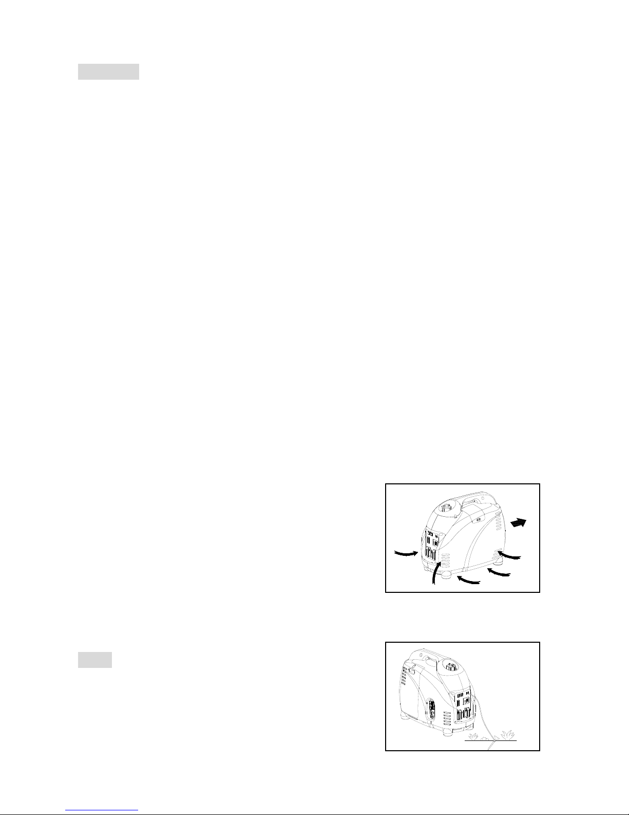
Be sure to carry the generator only by its carrying handle.
Place the generator on flat surfaces and keep clear of debris, this will
allow heat to dissipate freely.
4)ELECTRIC SHOCK PREVENTION
Never operate the engine in rain or snow.
Never touch the generator with wet hands or electrical shock will occur.
Be sure to ground (earth) the generator.
NOTE: ───────────────
Use ground (earth) lead of sufficient current capacity.
Diameter: 0.12mm (0.005 in)/ampere
EX: 10 Ampere --1.2mm (0.055 in)
──────────────────

6
1 2 3 4 5 67
813 15 16 17
19 20
910 14 1811 12
5)CONNECTION NOTES
Avoid connecting the generator to any commercial power outlet.
Avoid connecting the generator in parallel with any other generator.
CONTROL FUNCTIONS
DESCRIPTIONS
(1) Economy control switch
(2) Engine switch
(3)Fuel tank
(4) Spark plug
(5) Muffler
(6) Carrying handle
(7) Choke lever
(8) AC pilot light
(9)Overload indicator light
(10) Oil warning light
(11) DC protector
(12) DC receptacle
(13) AC receptacle
(14) Ground (earth) terminal
(15) Fuel filter
(16) Fuel tank cap
(17) Recoil starter
(18) Fuel valve
(19) Oil filler cap
(20) Air filter cover

7
1)OIL WARNING SYSTEM
When the oil level falls below the lower level, the engine stops automatically.
Unless you refill with oil, the engine will not start again.
2)ENGINE SWITCH
The engine switch controls the ignition system.
①“ON”(run)
Ignition circuit is switched on. The engine can be started.
②“OFF”(stop)
Ignition circuit is switched off. The engine will not run.
3)ECONOMY CONTROL SWITCH
When the economy control switch is turned “ON”, the economy control unit will
control the engine speed according to the connected load. The results are
better fuel economy and less noise.
4)DC CIRCUIT PROTECTOR
The DC circuit protector turns off automatically when the load exceeds the
generator rated output.
CAUTION: ──────────────────────
Reduce the load to within specified generator rated output if the DC circuit
protector turn off.
───────────────────────────
2
1
2
1

8
OFF
ON
5)FUEL VALVE
The fuel valve is used to supply fuel from the tank to the carburetor.
PRE OPERATION CHECK
NOTE: ────────────────────────
Add at least .5 gallons (2 liters) before attempting to start the engine the
first time.
Pre-operation checks should be made each time the generator is used.
───────────────────────────
1)CHECK ENGINE FUEL
Make sure there is sufficient fuel in the tank.
If fuel is low, refill with unleaded gasoline.
Be sure to use the fuel filter screen on the fuel filter neck.
Recommended fuel: Unleaded gasoline.
Fuel tank capacity: (see page 15,16)
WARNING: ──────────────────────
Do not refill tank whileengine is running or hot.
Close fuel valve before refueling with fuel.
Be careful not to admit dust, dirt, water or other foreign objects into fuel.
Do not fill above the top of the fuel filter or it may overflow when the fuel
heats up later and expands.
Wipe off spilt fuel thoroughly before starting engine.
Keepopen flames away.
──────────────────────────
2)CHECK ENGINE OIL
Make sure the engine oil is at the upper level of the oil filler hole. Add oil as
necessary.
Remove oil filler cap and check the engine oil level.
If oil level is below the lower level line, refill with suitable oil to upper level
line. Do not screw in the oil filler cap when checking oil level.
Change oil if contaminated.
1. Oil capacity: (see page 15,16)
Recommended engine oil:
32¡ã
F F
80¡ã
25¡ã
CC
0¡ã
or 10W-30
SAE #30
or 10W-40
SAE #20
or 10W-30
or 10W-40or 10W-40
or 10W-30
SAE 10W
FuelValve
Fuelfilter
Oilfillercap
0ºC
32ºF
80ºF
25ºC

9
OFF
ON
ON
ECON.
SW
OFF
ON
ENGINE
SWITCH
ON
OFF
API Service “SJ”
3)GROUND (Earth)
Make sure to ground (earth) the generator.
OPERATION
NOTE: ────────────────────────
The generator has been shipped without engine oil. Please note that
engine will not start without oil
Do not tilt the generator when adding engine oil. This could result in
overfilling and damage to the engine
───────────────────────────
1)STARTING THE ENGINE
NOTE: ──────────────────────
Before starting the engine, do not connect the electric apparatus.
Turn the economy control switch to the “OFF”position.
─────────────────────────
1. Turn the fuel valve lever to the “ON”position.
2. Turn the engine switch to the “ON”position
3. Turn the choke lever to the “│I ”position. Not necessary if the engine
is warm.
4. Pull the starter handle slowly until resistance is felt. This is the
“Compression” point. Return the handle to its original position and pull
swiftly. Do not fully pull out the rope. After starting, allow the starter handle
to return to its original position while still holding the handle. Grasp the
carrying handle firmly to prevent the generator from falling over when
pulling the recoil starter.
5. Warm up the engine.
6. Turn the choke lever back to the operating position.
7. Warm up the engine without a load for a few minutes.
OPEN

10
ECON.
SW
OFF
ON
USING ELECTRIC POWER
1. AC APPLICATION
(a) Check the AC pilot lamp for proper voltage.
(b) Turn the economy control switch to the “ON”position.
(c) Turn off the switch(es) of the electrical appliance(s) before connecting to
the generator.
(d) Insert the plug(s) of the electrical appliance(s) into the receptacle.
CAUTION: ─────────────────────
Be sure the electric apparatus is turned off before plugging in.
Be sure the total load is within generator rated output.
Be sure the socket load current is within socket rated current.
The economy control switch must be turned to “OFF”when using electric
devices that require a large starting current, such as a compressor or a
submergible pump.
──────────────────────────
2.OVERLOAD INDICATORLIGHT
The overload indicator light comes on when an overload of a connected
electrical device is detected, the inverter unit overheats, or the AC output
voltage rises. The electronic breaker will then activate, stopping power to the
generation in order to protect the generator and any connected electric devices.
The output pilot light (green) will flicker and the overload indicator light (red) will
turn on, then the engine will stop running. Once engine stalls the following steps
should be taken:
(a) Turn off any connected electric devices and stop the engine
(b) Reduce the total wattage of connected electric devices within the
application range.
(c) Check for blockages in the cooling airinlet and around the control unit. If any blockages are found, remove.
(d) After checking, restart the engine.
CAUTION: ─────────────────────────────────────
The generator AC output automatically resets when the engine is stopped and then restarted.
The overload indicator light may come on for a few seconds at first when using electric devices that require a large
starting current, such as a compressor or asubmergible pump. However, this is not a malfunction.

11
OFF
ENGINE
SWITCH
ON
OFF
3. DC APPLICATION (option)
This usage is applicable to 12V battery charging only.
(a) Charging instruction for battery
Disconnect the leads for the battery.
Loosen battery fluid caps if battery is not sealed.
Fill distilled water to the upper limit, if the battery fluid is low level.
Measure the specific gravity for the battery fluid by using the hydrometer,
and calculate the charging time in according with the table shown on right
side.
The specific gravity for the fully charged battery shall be within 1.26 to
1.28. It is recommended to confirm every an hour.
(b) Connect between the DC output socket and the battery terminals using
the charging leads. The leads shall be connected making sure of the (+)
and (-) polarity.
(c) The DC circuit protector is to be set to “ON” after confirming the
connection, if the protector is in “OFF” position.
CAUTION: ──────────────────────
Be sure the economy control switch is turned off while charging a battery.
───────────────────────────
3)STOPPING THE ENGINE
1. Turn off the power switch of the electric apparatus or disconnect any
electric devices.
2. Turn the engine switch to “OFF”position.
3. Turn the fuel lever to “OFF”.
.
3
2
1
C
Specific gravity 20¡ã
3. 47AH 20HR
2. 35AH 20HR
1. 30AH 20HR
Battery capacity
chargong time Hr 810
4620
1.06
1.14
1.10
1.22
1.18
1.26
1.30
Aim for specific gravity and charging time

12
PERIODIC MAINTENANCE
1)MAINTENANCE CHART
Regular maintenance is most important for the best performance and safe operation.
Item
Remarks
Pre-operation
check
(daily)
Initial
1 months
or 20 Hr
Every
3 months
or 50Hr
Every
6 months
or100Hr
Every
12 months
or 300Hr
Spark
Plug
Check condition adjust gap and
clean. Replace if necessary.
Engine
Oil
Check oil level
Replace
Oil filter
Clean oil filter
AirFilter
Clean. Replaceif necessary.
Fuel Filter
Clean fuel cock filter. Replace if
necessary
Choke
Check choke operation
Valve
Clearance
Check and adjust when engine
is cold.
Fuel Line
Check fuel hose for crack or
damage. Replace if necessary.
Exhaust
System
Check for leakage. Retighten or
replace gasket if necessary
Check muffler screen.
Clean / replace if necessary.
Carburetor
Check choke operation
Cooling
system
Check fan damage.
Starting
system
Check recoil starter operation.
Idle speed
Check and adjust engine idle speed
Fittings /
Fasteners
Check all fittings and fasteners
correct if necessary.
Crankcase
breather
Check breather hose for cracks or
damage. Replace if necessary
Generator
Check the pilot light comes on

13
oil filter
2)ENGINE OIL REPLACEMENT
1. Place the generator on a level surface and warm up the engine for several
minutes. Then stop the engine and turn the fuel lever to “OFF””.
2. Loosen the screw and remove the outer cover.
3. Remove the oil cap
4. Place an oil pan under the engine. Tilt the generator to drain the oil completely
5. Once oil has completely drained place the generator on a level surface.
6. Add engine oil to the upper level.
7. Install the oil filler cap
8. Install the cover and tighten the screw
Recommended engine oil: (see page 15,16)
API Service “ SJ”
CAUTION: ──────────────────────
Be sure no foreign material enters the crankcase.
Do not tilt the generator when adding engine oil. This could result in
overfilling and damage to the engine
Clean the oil filter every other 100hr.
───────────────────────────
3)AIRFILTER
Keeping the air filter clean is very important. Dirt induced through improperly
installed, improperly serviced, or inadequate elements will damage and wear
out the engine. Always keep the air filter element clean.
1. Remove the cover.
2. Remove the air filter cover and element.
3. Wash the element in solvent and dry.
4. Oil the element with air filter oil and squeeze out excess. The element
should be wet but not dripping.
5. Insert the element into the air filter housing.
6. Install the cover.

14
1
CAUTION: ──────────────────────
The engine should never run without the air filter element; excessive piston
and/or cylinder wear may result.
───────────────────────────
4)CLEANING AND ADJUSTING SPARK PLUG
1. Remove spark plug cover and plug
2. Check for discoloration on the electrode and remove any carbon build up.
3. Check spark plug type and gap.
4. Install the spark plug.
5. Install the cover
5)FUEL TANK FILTER
1. Remove the fuel tank cap and filter.
2. Clean the filter with solvent. If damaged, replace.
3. Once filter is clean, re-install it.
! WARNING ────────────
Be sure the tank cap is tightened securely.
─────────────────
6)MUFFLER SCREEN
! WARNING ─────────────────────
The engine and muffler will be very hot after the engine has been run.
Avoid touching the engine and muffler while they are still hot with any part
of your body or clothing during inspection or repair.
──────────────────────────
1. Remove the cover.
2. Remove the muffler screen.
3. Use a flathead screw driver to pry the spark arrester out from the muffler
Standard electrode color: Tan Color
Standard Spark Plug: CR4HSB (NGK)
Spark Plug Gap: 0.6-0.7 mm (0.024-0.028 in)

15
4. Remove the carbon deposits on the muffler screen and spark arrester
using a wire brush.
5. Install the muffler screen.
6. Install the cover
TROUBLESHOOTING
1)Engine won’t start
1. Fuel systems
No fuel supplied to combustion chamber.
No fuel in tank….Supply fuel.
Clogged fuel line….Clean fuel line.
Clogged carburetor….Clean carburetor.
2.Engine oil
Oil level is low….Add engine oil.
3. Electrical system
Poor spark
Spark plug dirty with carbon or wet….Remove carbon or wipe spark plug dry.
Faulty ignition system….Consult dealer.
4. Compression insufficient
Worn out piston and cylinder….Consult dealer.
2)Generator won’t produce power
Safety device (AC) to “OFF” …Stop the engine, then restart.
Safety device (DC) to “OFF” …Press to reset the DC protector

16
STORAGE
Long term storage of your generator will require some preventive procedures to guard against deterioration.
1)DRAIN THE FUEL
1. Remove the fuel tank cap, drain the fuel from the fuel tank
2. Remove the cover, drain fuel from the carburetor by loosening the drain screw.
2)ENGINE
2. Remove the spark plug, pour in about one tablespoon of SAE 10W30 or 20W40 motor oil into the spark plug hole
and reinstall the spark plug.
3. Use the recoil starter to turn the engine over several times (with ignition off).
4. pull the recoil starter until you feel compression.
5. Stoppulling.
6. Clean exterior of the generator and apply a rust inhibitor.
7. Store the generator in a dry, well-ventilated place, with a cover place over it.
8. The generator must remain in a vertical position.

17
SPECIFICATIONS
MODEL
CG3500i
GENERATOR
Type
Inverter Generator
AC Voltage
50Hz
100, 230V, 240V
60Hz
100, 120V, 240V
Max. Output
2.0 kW
2.5 kW
3.5 kW
Rated Output
1.8 kW
2.2 kW
3.0 kW
PowerFactor
1.0
DC Output
12V / 8.3A
ENGINE
Model
XY157F
Type
Air-cooled, 4 cycle, OHC, Gasoline Engine
Bore×Stroke mm×mm
52.4×57.8
52.4×57.8
57.4×57.8
Displacement
124.6cc
124.6cc
149.5cc
Max. Output
3.5KW / 5500rpm
3.5KW / 5500rpm
4.0KW / 5500rpm
Fuel
Regular AutomobileGasoline
Fuel tank Capacity
5.7 liters
Rated Continuous Operation
4h30min(100%
Load)5h50min
(50% Load)
4h10min(100%
Load)5h30min
(50% Load)
3h5min(100%
Load)4h10min
(50% Load)
Lubricatingoil
SAE 10W30
Lubricatingoil Capacity
0.9 liter
Starting System
Recoil Starter
Ignition system
C.D.I.
Spark Plug: Type
A7RTC
DIMENSION
Net dimension L×W×H
565×320×470
Overall dimension L×W×H
595×355×510
Net Weight
29 Kg
Dry Weight
32Kg
Specifications subject to change without prior notice.

18
Invert cell
PILOT
OVERLOAD
LOW OIL
M
Oil sensor
R
R
BL
O
BU
BL
R
R
BL
R
BL
Y/G
BL
BL
R
BL
BU
BU
BU
BU
BL
BL
R
BL
BL
BL
R
BL
W
W
BL
BL
BL
DC winding
Stepping motor
Main
Control
winding
winding Economic
switch
Engine
switch
R
O
W
BL
BU
R
O
BL
PI
BU
R
High
pressure
wrap
Spark
plug
BL
W
Spring winding
Ignition winding
R
BL
BR
GR
P
Y/G
W
O
BU
BU
FUSE
WIRE DIAGRAM
CG3500i

19
(888)-405-8725 Coleman Powersports
PO Box 7909, Tempe, AZ. 85281
www.colemanpowered.com
This manual suits for next models
1
Table of contents
Other Coleman Inverter manuals

Coleman
Coleman PMP3000 Series User manual

Coleman
Coleman 600 Watt WIND TURBINE User manual

Coleman
Coleman 55 WATT SOLAR 12 VOLT POWER GENERATOR KIT User manual

Coleman
Coleman PMP1200 User manual

Coleman
Coleman PMP3000 Series User manual

Coleman
Coleman 58050 User manual

Coleman
Coleman Powermate PM402511 User manual

Coleman
Coleman CM04143N User manual
Popular Inverter manuals by other brands

FRONIUS
FRONIUS Primo GEN24 quick start guide

Pro-tec
Pro-tec CTM-160 Instruction & maintenance manual

WhisperPower
WhisperPower W-GV 4 Scalino installation manual

Tripp Lite
Tripp Lite PowerVerter APSX6048VR owner's manual

Meec tools
Meec tools 740-062 User instructions

Ryobi
Ryobi RY906500S operating manual