Colifast ALARM User manual

USERS MANUAL
A L A R M
At-Line Automated Remote Monitor
COLIFAST ALARM:COLIFORMS IN WATER
© Copyright Colifast AS 2009
www.colifast.no
post@colifast.no
T: +47 67100510 F: +47 67100520

2
About this manual
This manual contains the most relevant instructions required for operation of the Colifast ALARM.
In addition, there are available quick guides for daily operation.
1SCOPE AND APPLICATION..................................................................................................................... 3
2SUMMARY OF METHOD.......................................................................................................................... 3
3APPARATUS AND EQUIPMENT ............................................................................................................. 4
3.1 COLIFAST ALARM .......................................................................................................................................................................... 4
3.2 SOFTWARE........................................................................................................................................................................................ 4
4COLIFAST ALARM INSTALLATION STEPS........................................................................................ 5
4.1 SITE .................................................................................................................................................................................................. 5
4.2 UNPACKING AND INSPECTION........................................................................................................................................................... 5
4.3 PLACEMENT OF THE INSTRUMENT .................................................................................................................................................... 5
4.4 INSTALLATION OF THE SAMPLE COLLECTOR FLASK......................................................................................................................... 5
4.5 CONNECTING CABLES AND TUBES (SEE FIGURE 4.1)........................................................................................................................ 5
5PREPARATION OF REAGENTS.............................................................................................................. 7
5.1 REQUIRED EQUIPMENT..................................................................................................................................................................... 7
5.2 REPLACING THE COLIFAST MEDIUM FLASK ..................................................................................................................................... 7
5.3 REPLACEMENT /REFILLING OF EXTERNAL REAGENTS AND WASTE................................................................................................. 8
5.4 PREPARATION OF THE 0.1M HCL SOLUTION .................................................................................................................................... 8
5.5 PREPARATION OF 10% SODIUM THIOSULPHATE SOLUTION.............................................................................................................. 8
6COLIFAST ALARM OPERATING PROCEDURE................................................................................. 8
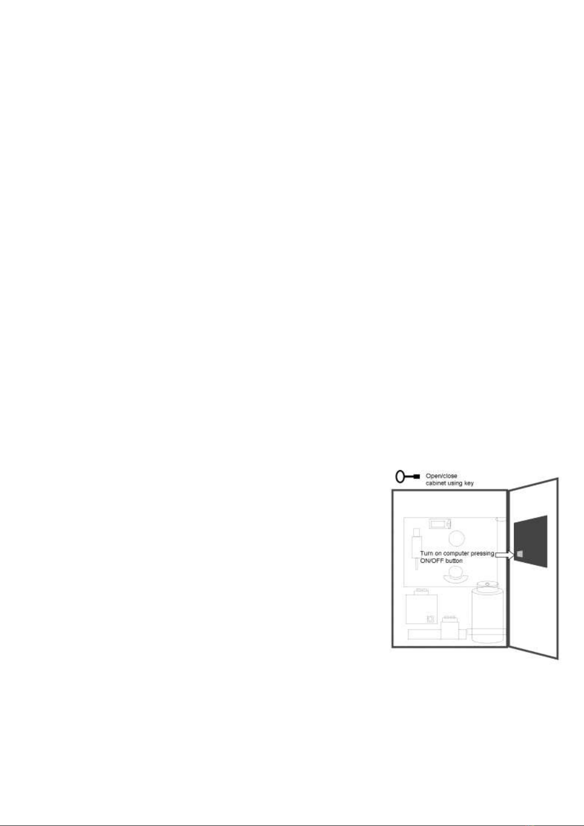
6.1 START-UP ......................................................................................................................................................................................... 8
6.2 INSTRUMENT CONTROL.................................................................................................................................................................... 9
SOFTWARE BASICS ...................................................................................................................................................................................... 10
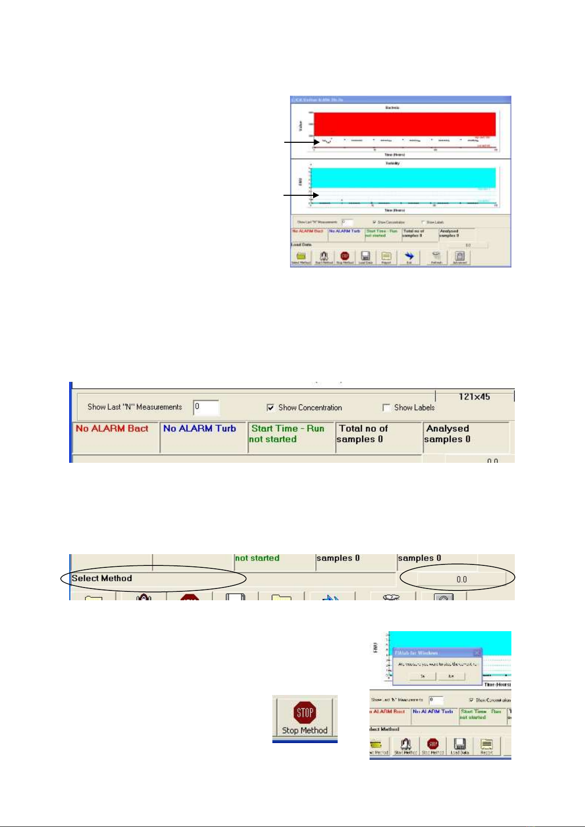
6.2.1 Results Plots.................................................................................................................................... 10
6.2.2 Information Boxes........................................................................................................................... 10
6.2.3 Instrument Run Status ..................................................................................................................... 10
6.2.4 Stop Method .................................................................................................................................... 10
6.2.5 Closing Software ............................................................................................................................. 11
6.2.6 Report File, Results and Copy......................................................................................................... 11
6.2.7 Loading Data from Previous Runs.................................................................................................. 12
6.2.8 Starting a New Run ......................................................................................................................... 12
6.2.9 Audio Alarm.................................................................................................................................... 12
6.2.10 Advanced..................................................................................................................................... 12
7REMOTE WARNING................................................................................................................................ 13
7.1 GSM MODEM SETUP...................................................................................................................................................................... 13
7.2 SMS ALARMS AND COMMANDS..................................................................................................................................................... 13
7.3 LAN REMOTE CONTROL ................................................................................................................................................................ 14
7.4 DIGITAL SIGNALS........................................................................................................................................................................... 15
8MAINTENANCE........................................................................................................................................ 15
8.1 BATCHWISE ROUTINES................................................................................................................................................................... 15
8.2 QUARTERLY ROUTINES .................................................................................................................................................................. 16
8.3 ANNUAL ROUTINES ........................................................................................................................................................................ 16
9INTERPRETATION OF RESULTS......................................................................................................... 18
9.1 METHOD:COLIFORMS P/A (PRESENCE /ABSENCE)........................................................................................................................ 18
9.2 METHOD:TURBIDITY (PARTICLES IN THE SAMPLE)........................................................................................................................ 19
10 TROUBLESHOOTING....................................................................................................................... 19
10.1 TECHNICAL ERRORS ....................................................................................................................................................................... 19
10.1.1 Self Diagnostics .......................................................................................................................... 20
10.2 METHODS /REAGENTS ................................................................................................................................................................... 23
10.3 OTHER............................................................................................................................................................................................ 23
11 APPLICATION NOTE - METHODS................................................................................................. 24
12 QUICK GUIDES AND SUPPLEMENTARY .................................................................................... 25

3
1Scope and Application
The Colifast ALARM (At-Line Automated Remote Monitor) is an automated system for detection of
total coliforms, thermotolerant coliforms or E.coli in 100ml water samples. The Colifast ALARM
automatically collects the water sample at programmed intervals. The system can automatically send
results to the control room / laboratory via LAN remote control, analogue signals or by mobile phone
network (SMS). In addition, the Colifast ALARM measures the turbidity level in water samples.
This system can detect down to 1cfu per 100ml, and results are obtained within 1-14 hours.
2Summary of Method
The Colifast technology consists of an analysing instrument and a bacterial growth medium. The
method is based on an enzymatic reaction. Colifast offers several types of medium / reagents which
will target and detect different types of bacteria. One of these reagents is the Colifast E.coli medium
which contains the substrate 4-metylumbelliferyl (MU)--D-glucuronide, and this substrate is
hydrolysed by the enzyme -D-glucuronidase that is present in E.coli. The fluorescent product 4-
methylumbelliferone (MU) is produced as a result of the hydrolysis reaction (Figure 2.1). The media
contains inhibitors to inhibit growth of non-coliforms.
O
O
O
R
CH
3
H
H
H
H
4-
methylumbelliferyl
-ß-
D-
glucuronide
Non-fluorescent
substrate
ß-D-
glucuronidase
OH
O
O
CH
3
H
H
H
H
+
OH
R
Fluorescent product
4-
methylumbelliferone
Figure 2.1 The Colifast technology is based on an enzymatic reaction. The substrate is hydrolysed by β-D-glucuronidase, and
a fluorescent product (4-methylumbelliferone) is produced.
The main components of the Colifast ALARM are the incubator reaction chamber, a flow injection
pump system for liquid handling and a detector system including wavelength specific emitters
combined with a spectrometer. The bacterial detection results are based on measured concentrations of
the fluorescent product (ppb MU). An increase in the number of E.coli means an increase in the
amount of -D-glucuronidase (enzyme). This leads to an increase in the production of MU (the
fluorescent product) that yields a higher fluorescence signal on the Colifast ALARM.
Incubator temperatures for the selection of thermotolerant coliforms 44 °C (42°C to 44.5°C) and total
coliforms / E.coli 37 °C (35°C to 39°C) can be programmed.
Turbidity is the cloudiness of a fluid caused by individual particles. The turbidity measured by the
Colifast ALARM is based on the nephelometric principle with the detector setup to the side of the
light beam. More light reaches the detector if there are large amounts of small particles scattering the
source beam than if there are few. Turbidity results are presented as FNU (Formazin Nephelometric
Units).

4
3Apparatus and Equipment
3.1 Colifast ALARM
The analyser comprise a touch-screen computer (operation), an incubator module / reaction cell
connected to light emitters and a spectrometer and fluidics operated by a six- position selector valve,
a stepper motor driven micro syringe and a peristaltic pump. The analyser is enclosed in a water and
dust protective enclosure with temperature controlled ventilation and numerous ports for power
supply, interface (LAN, analogue), external liquid and sample containers and visual and audio status
indicators.
Figure 3.1: Exterior features of the Colifast ALARM.
3.2 Software
The Colifast ALARM is operated by user-friendly custom instrument software with one window status
information and graphical presentation of results. Standard operation is limited to one button for
system start (new run). Data and report files are automatically generated and saved during a run.
Relay ports for
alarms and status
System port for
power supply, LAN
and GSM
Ventilation (fan)
GSM antenna
Transport handles
Status diodes
Touch Screen
system
computer
Door lock
Replace enclosed
reagents
Reagents ports for
external containers,
reagents and sample
On/Off switch audio
alarm

5
4Colifast ALARM Installation Steps
An overview of the chronological steps in the Colifast ALARM installation procedure is summarised
below. Detailed description of each step is presented in the subsequent sub-chapter.
4.1 Site
Define an appropriate place to install the instrument:
Site according to environmental specification: 0-35oC, < 95% rel.hum.
Available power: One vacant 110- 240V output
Water sample: nearby (< 3 meters) water / sample supply line with flow regulator
Available table or supporting wall (35 kg)
*Available GSM network signal
*Available LAN access
*Available input ports (relay on / off signal) on PLC or other industrial interface system
* Optional
4.2 Unpacking and Inspection
Check the packing list for missing parts.
4.3 Placement of the Instrument
Lift / move the instrument by using the transport handles (note: use both handles and avoid pressure
on the computer screen). Place on a solid / stable table / bench or secure on a supporting wall (35 kg)
using cabinet back plate mounting holes (warning: delicate units inside cabinet).
4.4 Installation of the Sample Collector Flask
Find a suitable place for the sample collector flask. Install it close to instrument but avoid places
where it may spill on the instrument and/or electrical components. Use a bracket if securing the
collector to a wall.
Use fittings to connect the ½’’ PVC tube from the water sample outlet to the sample collector inlet
(top). Use ½’’ PVC tubing to connect the sample collector outlet (side) to waste / drain situated lower
than the sample collector.
4.5 Connecting Cables and Tubes (see Figure 4.1)
Connect the white Teflon tubes (with fittings one end) from labelled liquid ports on the instrument to
the respective containers and sample collector (fittings in both ends). Cut tubes to appropriate lengths.
Connect the power supply to the 110-240V output. If interface is available on site, connect the LAN
cable and analogue relay outputs.

6
Figure 4.1: Cabling and external tubing of the Colifast ALARM.

7
5Preparation of Reagents
5.1 Required Equipment
Ready-to-use media flask.
Containers for 0.1M HCl, waste and 10% sodium thiosulphate (Na- thiosulfate).
37% Hydrochloric acid (HCl).
99% sodium thiosulphate, solid / powder.
Virkon tablets for disinfection.
Disinfectant cloth (70% EtOH).
Disposable examination gloves.
Note: Disinfectant and gloves are included with the Colifast Medium Flask.
Figure 5.1: Replacement of the Colifast Medium Flask.
5.2 Replacing the Colifast Medium Flask
1. Open cabinet.
2. Unscrew lid containing tube and carefully remove lid / tube from flask. Beware
contamination –use new and clean gloves.
3. Remove used / empty flask from cabinet.
4. Wipe and wash lower part of tube below lid (inside flask) with a disinfectant cloth.
5. After wash, remove lid from new flask.
6. Carefully insert flask in cabinet holder and insert tube and tighten lid.
7. Close cabinet.

8
5.3 Replacement / Refilling of External Reagents and Waste
Empty waste container (25 l) according to local regulations (may contain viable micro
organisms). If necessary, add 1 virkon tablet per 5 l waste for quick pre-destruction of
content. Let the tablets work for 20 minutes before emptying.
Fill / replace 0.1M HCl container (10 l) and 10% sodium thiosulphate solution (if
selected).
5.4 Preparation of the 0.1M HCl Solution
Add 8.4ml 37% hydrochloric (HCl) acid to 1 l pre-filtered or deionised water (84 ml 37%
HCl to 10 l water).
5.5 Preparation of 10% Sodium Thiosulphate Solution
Add 50g of 99% Sodium thiosulphate to 0,5 l pre-filtered or deionised water. Mix / stir
until completely dissolved.
6Colifast ALARM Operating Procedure
6.1 Start-up
Make sure all reagents, waste and sample line is ready
for use. Check that all external cables are connected
according to specification.
Power up instrument by connecting instrument power to
110V –240V supply. Set the power switch inside
cabinet in ON position. Units and relays should
initialize. The green power diode in front panel will
light. Open door and check incubator thermostat (display
temperature in red).
Press power on / off button on back panel of computer
(backside of door). The computer normally uses 1-2
minutes for staring up. When ready; a standard blue
desktop screen is displayed.
Note: If troubled by operating small buttons and screen icons: use the touch-screen pen.

9
6.2 Instrument Control
Open software by double touching <Colifast ALARM> icon on
computer desktop and wait for the instrument window to appear on
screen. It can take up to 30 seconds before the instrument window
appears on screen.
Check reagents and waste (ready for run).
Check method file for selected type of analysis run. If required, change to new file by one
touch on <Select Method>, search for required file in computer memory and select file by one
touch on <Open>. The new file will appear in top frame in program window.
Note: There are several available method files in computer memory. These are *.fia files for
standard 1 test per day analysis, continuous analysis, dual line sampling, reference sample,
disinfection run, and more. See separate application note for description of available method
files.
Start analysis by one touch on <Start Method>. After
approximately 5 seconds the pumps and valves will initialize
and start.

10
Software basics
6.2.1 Results Plots
Limit / threshold levels are indicated by colour.
Detector readings above threshold will indicate
presence of target bacteria (red) or high turbidity
(blue). This will activate selected alarms and
update report files and information boxes below.
6.2.2 Information Boxes
Information boxes shows the run status and latest alarms. Alarm for detection of bacteria is in box 1
(red) and high turbidity alarm in box 2 (blue). Alarms will be displayed with date and time for the
alarm. Analysis start date and time will show in box 3 (green) and will also indicate whether run is
completed or not started.
The total number of samples to be analysed in the complete run will show in box 4 (black) and the
number of samples ready analysed in box 5 (black).
6.2.3 Instrument Run Status
Below the information boxes the software displays the active instrument commands, and to the right
the active run time (from start). As long as the instrument is running, this time will count / update
approximately every 2 seconds. If this time does not update, the run has stopped / been completed.
6.2.4 Stop Method
Any run can be stopped by one touch on <Stop Method> followed
by <Yes> in the warning message.

11
6.2.5 Closing Software
The Colifast ALARM software can be closed by one touch on <Exit> followed
by <Yes> in the warning message.
6.2.6 Report File, Results and Copy
The software will automatically generate a folder with the date and time of the run start and will save
report files in this folder (*.txt and *.dat files). A new text file will be generated for every sample
analysed and the full report will be the file with the most recent date and time, labelled with “final” if
a full run is completed. The folder including the report files is found in the computer memory (C:
Colifast/Results). To access the results: double tap on the shortcut to results on the
computer desktop. The desktop is accessed by pulling the instrument software window
slightly to the right (touch, hold and drag the blue top bar). To copy result folders or
result files; open cabinet and insert a USB memory stick into the available USB port on
the computer back panel. Open Results folder and copy files by selecting the file/folder
(tap file name) and select the <Copy this file> (tap icon).
A new window will target the destination of the file-
copy. Select the “Removable Disc”and tap <Copy>. A
copy of the report file will be saved on the removable
USB stick. Close Results folder and centre instrument
window (drag or double tap on blue top bar). Remove
USB stick and close cabinet.
When a run is stopped by using <Stop Method>, an updated report file can be generated by one touch
on <Report> followed by entering a file name and selecting <Save>. The report file will appear on
screen.

12
Figure 6.1: Report file generated during run. Results from a sample containing target bacteria are shown in the second
column and the positive detection is indicated by “+” in the first column (red). The time and date after “Bact” indicate when
the analysis of this sample was started. The FNU turbidity value from a sample is shown in the third column (blue).
6.2.7 Loading Data from Previous Runs
Plots from previous runs can be regenerated by one touch on
<Load Data>, followed by selection of the specific run data file
(*.dat) in the computer memory. Touch the <Open> and
<Refresh> button in the software to see the results plot. A text
report based on this plot can be generated by one touch on
<Report> followed by entering a file name and selecting
<Save>.
6.2.8 Starting a New Run
One click on <Start Method> will start a run based on the method file selected.
If the previous run was stopped by error or use of <Stop Method >, the
software contains data which will generate a warning message. Touch <Yes>
in the massage and a new run will start. If the previous run is still active, this
will generate a warning message. Touch <OK> and, if preferred, stop the
previous run and start a new run.
6.2.9 Audio Alarm
Use the switch on the right side panel (by the liquid ports) to turn ON/OFF the audio alarm.
This alarms sounds when system detects target bacteria or measures high turbidity.
6.2.10 Advanced
The advanced option (<Advanced> button) is mainly for servicing and is not used in daily operations.
Bacteria results sample 1
FNU turbidity sample 3

13
7Remote Warning
7.1 GSM Modem Setup
The installation and setup of the GSM modem will be done by Colifast during production and
performance testing of the new Colifast ALARM unit.
Note: Colifast would need a functioning / active GSM SIM card and a description of contact number
(s) for the ALARM calls from the system.
Before first time use, the GSM alarm modem has to be configured with alarm telephone numbers,
access verification and message text. The modem requires one active SIM card with inactivated PIN
code and caller display (incoming number) active in the subscription.
Configure GSM Modem:
See separate MultiModem V3 user manual for programming
instructions.
Notes:
1. Use Serial cable (included accessory) and connect to serial
port on modem and to COM1 port on computer (remove
Syringe Pump Serial cable).
2. For full software (V3 configure) access, set PC screen
resolution to 1024X768 ( Start –Control Panel –Display –
Settings).
3. Use power switch (inside cabinet) to toggle power
according to software instructions
Remember to set screen resolution back to 600X800 after Modem
configuration. Remember to connect the Syringe Pump serial cable back to COM1.
The COM1 port might be disabled after Modem configuration which would generate a Syringe Pump
error in analysis run. Shut down and restart PC and cycle instrument power. Start new run and check
for errors.
7.2 SMS Alarms and Commands
Note 1: Make sure there is an available GSM network access on site.
Note 2: Make sure the GSM modem is configured with operational phone numbers.
Note 3: The following are default alarm text messages from initial configuration.
Check GSM Modem status by sending ? to the SMS alarm (only access
numbers) and it will send back an SMS with status info.
If system detects target bacteria or read turbidity above threshold level during analysis the
following SMS message will be generated: “Colifast ALARM: Bacteria detected / high
Turbidity”. The message will be sent to the number (s) specified in the modem
configuration.

14
If next analysis is negative (no bacteria and low turbidity) the following SMS message will be
generated: “Colifast ALARM: ALARM Reset”. The message will be sent to the number (s)
specified in the modem configuration.
If system detects a technical error or the run is complete or a Stop SMS is recieved, the
following SMS message will be generated: “Colifast ALARM: System Error / Stop”. The
message will be sent to the number (s) specified in the modem configuration.
When system is restarted after a stop the following SMS message will be generated:
“Colifast ALARM: System Activated”. The message will be sent to the number (s)
specified in the modem configuration.
Remote start a new run (if “..Mstart..” method is started) by calling the GSM modem number
(the caller number have to be in the modem access list). The system will reply with a tone and
the following SMS message: “Output is now ON” .
Remote stop a run (if “..Mstart..”method is selected) by calling the GSM modem number (the
caller number have to be in the modem access list). The system will reply with a tone and the
following SMS message: “Output is now OFF”. Note: Before starting a new SMS activated
run in software, remember to reset the start function (output = OFF). Call modem to get it in
OFF position or check status / position by sending ? to modem number.
7.3 LAN Remote Control
Note: The LAN remote access / control depend on a connection to an active TCP/IP network.
Open external access by double-tapping VNC remote icon on Colifast
ALARM computer desktop. When activated, there will be a small VNC
icon in the right corner of status bar (bottom of screen).
Check IP address by setting pointer at small VNC icon on status bar. Write down IP address
(Colifast ALARM) and use it to access instrument from a remote network connected
computer.
Install VNC (Viewer) software on external computer (for remote control).
Start VNC viewer (Start –All programs –RealVNC) on external
computer and add IP address for Colifast ALARM in server field in
connection window. Click <OK> and Colifast ALARM computer view
will open in new window.
VNC Server : 10.30.70.100

15
To end remote control session: Close VNC window by one touch on X (closing window) on
top right corner (blue frame) of the VNC program window.
Note: VNC gives unrestricted remote control, and all Colifast ALARM functions will be executable
from the external viewer window. The Colifast ALARM can be started and stopped by remote control
actions.
7.4 Digital Signals
The Colifast ALARM is equipped with 3 contact / no contact relays. The
relays indicate the following:
Relay 1 (N / O), contact: Positive bacteria analysis, bacteria
present in sample - alarm.
Relay 2 (N / O), contact: Turbidity level above set threshold
value –alarm.
Relay 3 (N / C), no contact: Technical / method error –alarm
These relays can be used for activation of remote alarms and the system control. Relay signals from
the Colifast ALARM require 3 available inputs and 1 signal current output from a nearby industrial
controller / PLC system.
Note: The system automatically reset all alarms, no manual reset required.
8Maintenance
8.1 Batchwise Routines
Batchwise routines are performed when a new medium flask is replaced (normally every 20.days).
Inspect system for any physical damage / irregularity or liquid leaks.
Inspect inside of cabinet for any irregularities and verify that overfill flask and tray are empty
and dry.
In case of damage or leakage: Please check system / tubes / connectors. Replace damaged
component before starting new run or contact Colifast for support and service.
Remove used medium flask after removing lid and tube, clean medium tube with 70+%
ethanol, and install new flask. Use gloves.
1
2
3

16
Empty waste container. The contents should be disposed of according to prevailing
regulations.
Fill 0.1M HCl container.
Additional if in use:
Check / replace external sample collection flask.
Fill 10% Sodium Thiosulphate container.
8.2 Quarterly Routines
Quarterly routines are performed after 3 months of continuous operation.
Change the peristaltic tube by releasing the lever of the pump and remove the tube fittings
from the peristaltic tubing. The new tube needs to be stretched slightly before cutting one
15cm long piece for replacement. Reinsert the new tubing and reposition the lever. Ensure that
the tubing going from the reaction flask reservoir delivers to the waste port no.2.
Visually check all tubes, connections and fittings for damage or wear. Visually check glass
barrel of syringe for wear. Replace parts if necessary. For technical support and spare parts,
please contact Colifast or your local distributor.
Examine reaction flask (square plastic flask in incubator) by carefully pulling it up from the
incubator (remember orientation of flask). The flask should be clean with clear walls. Contact
Colifast or your local distributor if flask is damaged or flask-walls are found unclean. Reinsert
flask gently down in incubator (down to bottom) with original orientation.
Do a general visually system inspection (inside and outside) and check for any damage or
wear. For technical support and spare parts please contact Colifast or your local distributor.
8.3 Annual Routines
Annual routines are performed after 12 months of continuous operation. The annual service is
recommended to be performed by Colifast or the local distributor.
The following are a brief summary of the annual service:
Remove all Teflon tubing and peristaltic tubing inside and outside cabinet. Remove the
Medium Air Lock. Cut new tubing using a tube cutter and use the old tubing as guide for
finding the correct lengths. Note. Measure and note position of tube inside the reaction flask
and overflow flask. New tubing should be inserted in similar positions. Do not insert new
tubing until valves, seals and flasks are serviced.
Fill a separate test flask (hole in lid for thermometer) with approximately 100 ml of water and
insert down in incubator. Add a thermometer and continue servicing. Check temperature after
30 –60 minutes and adjust offset in thermostat if necessary.

17
Carefully unfasten and remove the front section (with liquid ports) of the multiposition valve
using a 7/64’’ umbraco key. Replace the small plastic disk in center bracket with a new one
(with similar positioning in bracket). Carefully re-mount front section (with o-ring) and
tighten.
Check syringe pump glass barrel and piston seal carefully. If any signs of wear or liquid leaks,
replace seal or barrel (normally seal only). Replacing syringe seal: Touch <Advanced> in
software and enter password / code. The program setup window will appear. Touch <FIAlab>
and the pump control window will appear (Sequential Injection Analysis). Touch <Logon>
and the system will initialize and state “Logon successful” after approximately 10 seconds.
Enter 20000 in Volume and 500 in Flowrate (on-screen keyboard) and touch arrow down by
the pump illustration. The pump will go down 4/5 of the total length. Un-tighten the lock
device on top of barrel and remove the screw at bottom of barrel (at the piston). Carefully
unscrew and release the barrel. Carefully pull out the piston and replace the white piston seal.
Wash the inside of barrel with water and a soft cloth. Replace piston with seals and mount
barrel back in place (remember to tighten barrel and bottom screw). Go to Sequential Injection
Analysis window and touch arrow up. The syringe will return to initial position. Close all
open windows using <Exit>.
Check the Bulkhead Unions (nut-nut adaptors) for damage or wear. Replace if necessary
(remember to tighten properly).
Fit all new tubes to the specific positions using new nuts and ferrules for fitting. Remember to
copy the previous tube lengths inside flasks (approx.: peristaltic line to bottom of flask,
syringe line 1cm down from lid, ventilation / overfill line 3cm down from lid). Insert new
Medium Air-Lock. Insert new peristaltic tube. The new tube needs to be stretched slightly
before cutting one 15cm long piece for replacement. Reinsert the new tubing and reposition
the lever. Ensure that all tubing are secured tightly and allocated to correct positions. Use
tape/stips to lock tube-positions in reagent flasks (similar to previous tubing).
Replace reaction flask (read temperature and remove test-flask). Tighten lid with tubing to
new flask and carefully insert the flask to bottom of incubator. For turbidity calibration,
please contact Colifast or local distributor for turbidity standards, calibration procedure and
files.
Check / refill reagents.
Start test-run by opening software and selecting (<Select Method>) test Method. Run test by
one touch on <Start>. Check 100ml filling volume after test: Carefully remove reaction flask
from incubator (remember position in incubator), remove lid and measure volume by
emptying the flask into a measuring cylinder or a container on a tared scale. Tighten lid and
carefully replace flask into bottom of incubator (remember positioning).
Examine overfill flask and reservoir, clean out spill and dirt. Check cabinet ventilation / fan by
turning the fan-thermostat down. After test, adjust fan-thermostat back to original setting.
Use test data and visual inspection to search for any errors or spills. Repair / adjust if
necessary. Write down test and service data for report.
Select standard run file by <Select Method>. Check / refill reagents and start new run (<Start
Method>) according to operation plan.
Copy old result-files from computer Results folder to a USB memory stick. Remove/delete old
files from computer (clear memory space).

18
9Interpretation of Results
9.1 Method: Coliforms P/A (Presence / Absence)
The Colifast ALARM measures the development of fluorescence in samples. An increase of
fluorescence indicates activity of the enzyme -galactosidase (or -glucuronidase for E.coli) which
indicates the presence of coliforms in the sample. If the fluorescence signal from the Colifast ALARM
is plotted as a function of time, curves like the one in Figure 9.1 are obtained. When bacteria are
transferred to a new environment e. g. the Basic Colifast-6 medium, growth will normally occur after a
time-period called the lag-phase. During the lag-phase, the bacteria will adjust their metabolism to the
new environment / medium and sub-lethally damaged cells may be resuscitated. When the bacteria
start to grow and multiply it happens exponentially, and this is called the exponential phase. The
development of fluorescence in the samples analysed by the Colifast ALARM follows a pattern
similar to bacterial growth which consists of a lag-phase and an exponential phase. If the samples
contain high levels of coliform bacteria, a linear increase of fluorescence is usually observed in the lag-
phase (Figure 9.1).
-10
0
10
20
30
40
50
60
70
80
0
100
200
300
400
500
600
700
Time (minutes)
Fluorescence (ppb)
Figure 9.1: Fluorescence from river water samples. The fluorescence follows a pattern similar to bacterial growth and
consists of a lag-phase and an exponential phase. High numbers of coliform bacteria give an early increase in the
fluorescence. Lower numbers of coliform bacteria require a longer incubation time before a logarithmic increase in
fluorescence is seen.
The PA (Presence/Absence) method is based on determining the fluorescence value after a given time
of incubation. If the fluorescence value is above a threshold value, a presence result (ALARM) is
indicated. If the fluorescence value is below the threshold value, an absence result is indicated. This
method is useful for water samples containing low levels of bacteria where presence/absence results
are of interest In addition, the Colifast ALARM will measure fluorescence several times during
incubation and a early positive result, ahead of the final measurement, indicate higher levels of
bacteria (>1 target bacteria per 100ml).
Lag
phase
Exponential phase
~100 cfu/5 ml
>100 cfu/5 ml
~50 cfu/5 ml

19
Figure 9.2: A positive result will activate selected alarms and will be noticeable in analysis plot, information box, audio
alarm and alarm diode. Black circles: Information showing a positive bacterial analysis.
9.2 Method: Turbidity (Particles in the Sample)
In addition to microbial analysis, the Colifast
ALARM detects turbidity in the sample by
measuring light scattering in the infrared spectrum.
It uses a detector setup to the side of the light beam
(nephelometer). More light reaches the detector if
there are large amounts of small particles scattering
the light beam than if there are few. The calculated
turbidity value from a sample measurement is based
on calibration standards with known values. The
measuring scale for Colifast ALARM would
normally give accurate results from approx. 0.2
FNU to approx. 20 FNU. Turbidity values above the
set threshold level (calculated in software) will
activate selected alarms and will be presented in the
analysis plot and information box, and also by the
alarm diode and audio alarm.
10 Troubleshooting
10.1 Technical Errors
Figure 9.3: Nephelometric principle

20
No response from system and computer: Check power supply and power switch inside
cabinet and computer power button. Check power fuse (aut. 5A) and cabinet temperature fuse
(450C). Check for any loose cables and temperature setting for the cabinet ventilation (25-
300C).
10.1.1 Self Diagnostics
The Colifast ALARM monitors temperatures, pumps, valves, liquid flow, reagents, detector and
results during operation and will generate error messages on the screen if any malfunction is detected.
The following describe some errors detected by and presented by system software:
Contamination of media. The diagnostics will
show the following messages if the liquid
growth medium (from flask) somehow are
contaminated. Check medium flask inside
cabinet: Long and greasy elements are normally
visible when contamination. Note: Small
particles may occur by natural precipitation.
When pressing <OK>, a new message will
appear notifying user to start contamination
wash program. Press <OK> and press <Select
Method> Find and open the “contam wash..”
file. Start the new method <Start Method>, and
follow the instructions on screen, including collection of rinse solution and alcohol
disinfection of flask tube.
Table of contents
Popular Industrial Equipment manuals by other brands

Syn-Tech Systems
Syn-Tech Systems FuelMaster Plus Operation manual

KAM
KAM Simple Precision IAS user manual

AERMEC
AERMEC SAP 0075 Booklet

Idex
Idex BAND-IT S75099 Owner Manual and Tool Operating Instructions

USA Industries
USA Industries GRIPSAFE Series installation manual

Aeroex Technologies
Aeroex Technologies ROX-400 Installation & service manual