Coltene SPEC 3 User manual

IT
Owner’s Guide
Ръководствозапотребителя
用户指南
Příručka vlastníka
Brugsanvisning
Gebruikershandleiding
Omaniku juhend
Omistajan käyttöopas
Guide de l’utilisateur
Benutzerhandbuch
Εγχειρίδιο χρήσης
Kezelési útmutató
Guida per l’utente
取扱説明書
Naudotojo instrukcija
Brukerhåndbok
Instrukcja użytkowania
Manual do utilizador
Приручник за кориснике
Príručka majiteľa
Manual del usuario
Bruksanvisning
Kullanıcı El Kitabı
JP
LT
NO
PL
PT
SR
SK
ES
SV
TR
EN
BG
ZH
CS
DA
NL
ET
FI
FR
DE
EL
HU www.coltene.com


TABLE OF CONTENTS
Caution: Federal (United States) law restricts this device to sale by or on the order of a licensed healthcare practitioner.
I. Introduction 4
II. Safety 4
III. Parts and Descriptions 6
IV. Installation 7
V. Operations and Controls 8
VI. Troubleshooting 10
VII. Cleaning, Disinfecting and Sterilizing 11
VIII. Technical Details 13
IX. General Information 14
X. Ordering Information 15
XI. Electromagnetic Compatibility 16

4S.P.E.C. 3®LED Curing LIght
EN
S.P.E.C. 3®LED Curing Light
I. Introduction
S.P.E.C. 3®LED is a curing light intended for rapid polymeriza-
tion of light-cured materials by dental professionals. This product
effectively reduces polymerization time on various light-cured
materials and provides excellent treatment results. S.P.E.C. 3®
LED’s body is made from industrial-grade aluminum which ensures
its durability and excellent heat dissipation. The S.P.E.C. 3®LED
features multiple curing modes (3K Mode, Standard Mode, Ortho
Mode) for maximum functionality.
Indication For Use: This product can be used for intra- and
extra-oral polymerization of visible light cured dental materials
with Camphorquinone (CQ) photoinitiators. The wavelength
output is 430nm–490nm.
II. Safety
S.P.E.C. 3®LED Curing Light is designed and manufactured in con-
formity with applicable safety standards. To prevent damage to
equipment and risks for patients, users, and third parties, please
follow the safety notes and operate with care. Liability can not be
accepted for damage resulting from misuse or failure to operate
in compliance with the safety notes.
2.1. Explanation of symbols
Direct Current
CAUTION
Consult
accompanying documents
Manufacturer
ELECTRIC SHOCK
Caution for
electric shock. Risk of fatal injury if
instructions are not followed.
Manufacturer date
NOTE
Consult
Instructions For Use
Serial No. Type B applied part
Level of protection against electric
shock.
Keep dry Fragile
Unstable Use no hooks/
Do not puncture
Class II Equipment
Double Insulated
Equipment
Do not look directly into light
emitted from LED
104˚F
40˚C
-5˚C
23˚F
Temperature Limitation
%
10%
85%
Relative Humidity
Non-Ionizing Radiation
80 kPa
106 kPa
Atmospheric Pressure
2.2. Transport damage
Check the device for any damage after receiving it. If damaged,
immediately report to the transportation company within 24
hours from the date of receipt. Under no circumstances, work
with a damaged curing light.
2.3. Operator’s obligations
Users must be trained and comply with state or local regulations
in force for this type of device.
2.4. Safety instructions
Before putting the device into operation, read this manual
thoroughly and follow the instructions to avoid any misuse or
damage especially related to user and patient’s health. Do not use
this device without proper eye protection for the operator,
assistant and patient.
WARNING
Electric Shock Hazard
• Before using the device, check the power
cord and plug for damage. If they are
damaged, do not connect the equipment
to the mains power.
• Do not immerse the product in water.
Moisture should be avoided. Electric
shock could occur.
• Keep the product in a dry and clean
place. Exposure to moisture increases
the risk of electric shock.
• Failure to comply may result in injury or
death to personnel.

Owner’s Guide 5
EN
Only use authorized spare parts and accessories supplied by
Coltène®.Use of parts other than those recommended may dam-
age circuitry and will void product warranty. Repair or disassembly
of this device must be done by authorized personnel only.
Coltène®is not responsible for any damage caused by the
following:
•Improper repair or maintenance service performed by
unauthorized personnel or facilities.
•Use of any unauthorized replacement parts or accessories.
WARNING
• S.P.E.C. 3®LED Curing Light produces
high-output light energy. Do not look
directly at the light emitted from this
curing light. Retinal damage may ocurr.
• Patient, clinician and assistants should wear
UV orange eye protection when this device
is in use. Retinal damage may occur.
CAUTION
• After use, place the handpiece on the
charger base securely. Failure to properly
secure the handpiece in the charger base
may result in an incomplete battery charge.
• Light output from this light may be
signicantly increased compared to other
polymerization devices; therefore when
using this device determine the curing time
of your material using the enclosed test
block.
• Do not drop the handpiece or light guide.
Device damage may occur.
• Avoid electromagnetic radiation generated
from other electrical appliances, as they
may cause the product to malfunction.
WARNING
• Take caution when using this product in the
presence of a ammable anesthetic mixture or
an oxidizer like oxygen or nitrous oxide. This
device may act as an ignition source.
• DO NOT expose soft oral tissues at close
proximity or burns may occur. Maintain a safe
distance between the light guide tip and the
soft tissue.
• If using the S.P.E.C. 3®LED Curing Light in
the Standard Mode and in close proximity of
the gingival tissue, DO NOT expose tissue for
more than 5 seconds or minor burns may oc-
cur. If longer curing time is required, consider
a dual-cure product (composite or adhesive).
Irradiance output in High Power Mode is 1600
mW/cm².
• In 3K Mode, DO NOT expose soft tissue for
more than 2 seconds or burns may occur. If
a longer cure is needed, consider a dual cure
product (composite or adhesive). Irradiance
output in 3K mode is 3000mW/cm2.
• Barrier sleeves are single patient use only.
Barrier sleeve must be used to prevent patient
cross contamination.
• Persons having a history of photosensitizing
drugs should not be exposed to light from
this light.
• Adjust curing techniques in accordance with
the increased energy. Pulpal and soft tissue
damage may occur if excessive energy is
applied to a restoration.
Failure to comply with these warnings may
result in injury to personnel.

6S.P.E.C. 3®LED Curing LIght
EN
III. Parts and Descriptions
As you remove each item from the box, ensure all box contents
are in good condition. If items are missing or damaged, contact
your supplier for immediate assistance.
1. HANDPIECE The handpiece is equipped with high-power
LEDs and its control panel is located on the
front part.
2. LIGHT GUIDE
(8MM TURBO)
The output of the Curing Light LED is emitted
from the end of this piece (autoclavable).
3. LIGHT SHIELD This shield protects the eyes from the light
emimited from the light guide during use.
4. CHARGER BASE
(6V DC, 2.5A)
The charger base is for the cordless curing
light only. Always place the handpiece on the
charger base when not in use.
5. POWER ADAPTER Please use the original power adapter at all
times.
6. AC POWER CORD Please use original AC power cord (at all
times).
7. OWNER’S GUIDE S.P.E.C. 3®LED Curing Light Owner’s Guide.
8. BARRIER SLEEVES Use for infection control.
9. COMPOSITE CURING
TEST BLOCK
Test curing times and depth of cure.
2.5. Safety Notes
1. Before use, check if the device is working properly and has
no visible damage.
2. The ber-optic light guide is provided in a non-sterile
condition and must be sterilized prior to patient contact.
3. In case of device malfunction, discontinue use and
refer to the ‘Trouble shooting’ section in this Owner’s
Guide. If the problem persists, contact our service center
immediately.
4. Do not attempt to repair, disassemble or remodel
this product without the manufacturer’s permission
(Coltène®). Otherwise, product warranty will be voided.
5. The handpiece is not autoclavable. Do not sterilize the
handpiece by immersion or heat sterilization such as dry
heat, steam under pressure, or unsaturated chemical
vapor (ber-optic light guide and light shield can be
autoclaved).
6. Using barrier sleeves will reduce the light output by
5-10%. Due to the high output power of the S.P.E.C.
3®LED Curing Light, curing has been shown to be
substantially equivalent.
2.6 Environment Protection
This appliance is labeled in accordance with European directive
2002/96/EC concerning used electrical and electronic appliances
(waste electrical and electronic equipment–WEEE). This guide-
line determines the framework for the return and recycling of
used appliances as applicable throughout the EU. The symbol on
the product, or on the documents accompanying the product,
indicates that this appliance may not be treated as household
waste. Instead it shall be handed over to the applicable collection
point for the recycling of electrical and electronic equipment.
1
4
5
6
8
9
Owner’s Guide
7
10
11
12
2
3

Owner’s Guide 7
EN
10. PHILLIPS HEAD SCREW
DRIVER
Use to remove the battery pack.
11. HANDPIECE COVERED
BY BARRIER SLEEVE
Place Eye Shield over both.
12. EYE SHIELD This shield protects the eyes from the light
emitted from the light guide during use.
IV. Installation
IMPORTANT
• For proper operation, the power adapter and charger
base must be installed and used in a dry environment.
If the charger base becomes wet, unplug it immediately
and dry thoroughly before plugging it in and inserting the
handpiece.
• Do not place the handpiece into the charger base
until it has reached room temperature. Humidity and
condensation could damage the electronics.
• The power adapter is designed for use within a voltage
range from 100-240V, 50-60Hz. Ensure that the required
voltage is available before connecting the power cord
to the power adapter. Failure to do so may damage the
electronics.
• Use only the power adapter supplied by Coltène®with
the S.P.E.C. 3®LED Curing Light.
• Do not use the device unless the power cord is rmly
inserted into the electrical outlet.
Connecting the S.P.E.C. 3®LED Charger Base:
1. Insert the power adapter cord (Fig. 5) into the receptacle
in the charger base (Fig. 4).
2. Place the charger base on a level and secure surface.
3. Insert the AC power cord (Fig. 6) into the power adapter
(Fig. 5).
4. Plug the other end of the AC power cord (Fig. 6) into an
electrical wall outlet.
5. Insert the handpiece into the charger base. Verify that the
charger base LED is illuminated orange which indicates
that the device is charging. An illuminated green LED
indicates the light is fully charged.
Charging the battery pack:
• The handpiece should be placed on the charger base
when battery is low or not in use.
• Before using the S.P.E.C. 3®LED Curing Light for the rst
time, please charge its battery for 24 hours.
• Make sure the handpiece is properly connected and
placed on the charger base. Do not force t.
• When the battery is low or discharged, the handpiece
will not operate or maintain low power output. Place the
handpiece on the charger base immediately for 2-3 hours
before attempting to use.
• Charging in progress: ORANGE light is ON
• Charging complete: GREEN light is ON
NOTE: Do not operate the device while being charged on the
charger base.
4.1. Installation procedure
1. Gently insert the light guide into the opening on the hand-
piece. When light guide is fully inserted, approximately 1mm
of the metal ring will be exposed.
2. Place the barrier sleeve over the curing light. Put the eye shield
over the end of the light guide drawing the barrier sleeve taut.
3. Plug the AC power cord into the receptacle in the power
adapter.
4.
Connect the S.P.E.C. 3
®
LED Charger Base to the power adapter.
Insert the plug on the power adapter completely into the wall
electrical outlet.
5. Keep the handpiece on the charger base when not in use.

8S.P.E.C. 3®LED Curing LIght
EN
CAUTION
• If the light or eye shield obstructs view of the
restoration, UV eye protection may be worn as
an alternate means of protection.
• Do not expose the device or the power supply
to extreme temperatures or open re. Operate
in ambient temperatures. (recommended
temperature: -5°C~+40°C (23°F~104°F).
Malfunction may occur.
• The S.P.E.C. 3®LED Curing Light will only
function properly if all of its components are
in good operating condition. Check the device
components thoroughly before use.
- Ensure no components are damaged or
deformed.
- Ensure the main plug and the electrical outlet
socket are compatible.
- Check to see if the power cord is damaged.
• When the battery level is critical, the LED display
will turn to ORANGE and start blinking: Please
fully recharge the S.P.E.C. 3®LED handpiece by
placing the handpiece on the charger base for
2-3 hours. Failure to fully recharge may reduce
battery life.
• Built-in automatic cool-down protection mode:
The S.P.E.C. 3®LED handpiece will not function
if its surface temperature is above 45°C (113°F)
for user’s safety. The light will ash alternately
between green and orange in the cool-down
protection mode. Place the handpiece into the
charger base and allow the light to cool down
for 5 minutes then try again.
V. Operations and Controls
Control Panel
OM
15
10
5
Shot switch Mode switch
5.1. Powering ON and OFF
• The battery charge level display:
Three green lights indicate a fully charged LED curing light.
One or two green lights indicate the curing light is not
fully charged. The unit beeps one time after displaying the
battery charge level indicating the LED is ready to use.
• Power ON: Press the Shot switch or the Mode switch to
activate the S.P.E.C 3®Curing Light.
• Power OFF: S.P.E.C. 3®LED Curing Light turns off
automatically after 5 minutes if no operation is detected
(Sleep mode).
• If the curing light is in ”Sleep” mode, pressing any
switch will “awaken” the light to the curing mode last
used.
5.2. Basic Controls
• Mode switch:
- Press the Mode switch quickly to select various time
settings.
- Press and hold the Mode Switch for 3 seconds to
switch between curing modes. Two beeps are emitted.

Owner’s Guide 9
EN
• Shot switch:
- Press the Shot switch to start the selected curing
program.
- Press the Shot switch during operation to stop the
program in progress.
5.3. Mode selection
• 3K Mode/Ortho Mode: When selected, the LED
display turns to ORANGE color. The output will be 3000
mW/cm².
• Standard Mode: When selected, the LED display turns
to GREEN color. The output will be 1600 mW/cm².
Press and hold the Mode switch for 3 seconds to change
curing mode (GREEN and ORANGE light changes alternately).
5.4. Polymerization time setting
• 3K/Ortho Mode: Quickly press the Mode switch
sequentially on ORANGE light to toggle the light through
the 4 time settings
(1sec. - 2sec - 3sec. - Ortho Mode).
Ortho Mode (Orange) Recommended for curing a full arch of
orthodontic brackets, or 16 brackets total. When activated, the
light will cure for approximately 3 seconds for each mesial or
distal side. A visual half-second blink and an audible beep will
indicate when each bracket side has been cured.
OM
15
10
5 1
2
3
OM
15
10
5 1
2
3
OM
15
10
5 1
2
3
OM
15
10
5 1
2
3
1 Sec. 2 Sec. 3 Sec. Ortho
Mode
(ORANGE)
Standard Mode (GREEN): Quickly press the Mode switch
sequentially on GREEN light to toggle the light through the 3 time
settings (5 sec. -10 sec. - 15 sec.).
OM
15
10
5 1
2
3
OM
15
10
5 1
2
3
OM
15
10
5 1
2
3
5.5. Composite Curing Test Block Instructions
For Use
Manufacturer’s recommended composite curing times are typi-
cally based on curing 2mm increments with a minimum accept-
able visible light output of 300mW/cm2. For curing lights that
provide signicantly higher output, the test block enables the
user to evaluate high power curing and adjust either the time or
increment thickness based on the results. In general, the required
curing energy is a constant function of the light output and time
(mW/cm2xsec). Changes in one factor can be offset by adjusting
the other. As an example, doubling the light output (mW/cm2)
may reduce the curing time (sec) by half. This relationship can
be used as a guideline for establishing composite curing test
parameters.
The test block is used to determine the curing rate at varying
thickness, of a selected combination of composite material and
curing light. To use the test block:
1. Place the block on a mixing pad or similar smooth
surface, test (bottom) side down.
2. Fill a selected opening (typically the 2 mm deep hole),
ush to the top surface, with the composite to be tested.
5 Sec. 10 Sec. 15 Sec.
(GREEN)

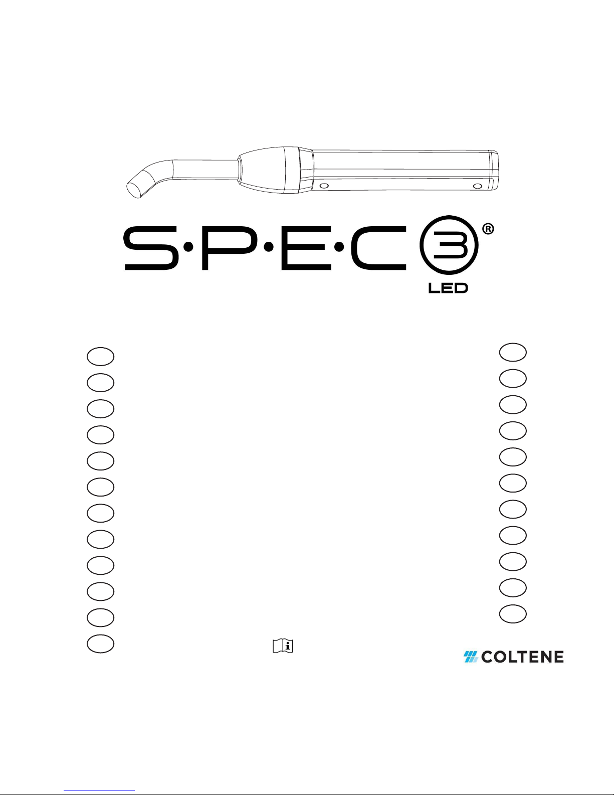
10 S.P.E.C. 3®LED Curing LIght
EN
3. For the best results, cover both sides of the lled opening
with a clear plastic matrix strip to eliminate the air
inhibited layer common with resin curing.
4. Cure the material, from the top, for a chosen length of
time.
5. After removing any clear matrix, check the hardness
of the cured composite from the bottom by scraping
the surface with a tungsten carbide carver or similar
instrument.
6. Inspect this cured surface. Ideally, it should resist
indentation and there should be no soft material that can
be removed by the instrument.
7. Repeat the procedure as necessary to determine an
optimum combination of curing time and increment
thickness for the material.
NOTE: Darker shades within a line of composites normally require
additional curing time. Please refer to the material manufacturer’s
instructions for use.
NOTE: Light output may vary depending on the light guide used.
VI. Troubleshooting
Please try the following procedures to rectify the common
problems listed below. Contact the manufacturer’s customer ser-
vice department for all other problems encountered.
• If the Shot or Mode button doesn’t light up
- Removing the battery pack and reinserting it will reset
the device to its original factory settings. On the base
of the handpiece, remove the two miniature screws
with the enclosed phillips head screw driver provided.
Slide the battery pack out of the handpiece and
reinsert it, replacing the two miniature screws.
- Place the handpiece on the charger base to recharge
until the red light changes to the green illuminated
light indicating a fully charged curing light.
This will resolve a low-power problem.
- Ensure that the power adapter is plugged into the
charger base securely. Ensure that the AC power cord
is plugged into the power adapter and the wall outlet
securely.
• If the Shot or Mode button lights up but doesn’t
work properly
- The curing light may be discharged and needs
recharging.
- Place the handpiece on the charger base to recharge
until the red light changes to the green illuminated
light indicating a fully charged curing light.
- If the curing light does not activate, the unit requires
service. Please contact your supplier or authorized
service center.
• If the S.P.E.C. 3®LED Curing Light doesn’t
polymerize light-cured materials well
- Ensure that a blue LED light is emitted from the light
guide. Do not look directly into the light output.
- Make sure the light guide is inserted into the opening
on the handpiece completely. Even a slight gap
between the light guide and LED may reduce the
polymerization light output up to 50%.
- Check the light guide for any damage. If the light
guide has an inner crack even though its surface looks
good, it may interrupt proper light emission.
- Check if there’s any debris, such as resin residue or
sealant on the tip of the light guide.
- Ensure that appropriate mode and time setting is
selected according to the type of light-cured material
being used.
- Make sure the light cured dental material is stored
according to the manufacturer’s suggested storage
and that the date on the material’s package has not
expired.

Owner’s Guide 11
EN
- Check curing depth and time using the enclosed test
block. See Composite Curing Test Block Instructions.
(Section 5.5)
• If the LED light is ickering or unstable
- Please contact our customer service representative for
assistance.
VII. Cleaning, Disinfecting and Sterilizing
Cleaning and Disinfection Instructions must be followed
after each use. Polyethylene lm barrier sleeves supplied with
the S.P.E.C. 3®LED Curing Light are single use and non-sterile.
The purpose is to aid in infection control by addressing cross
contamination. Ensure that a new undamaged barrier sleeve is
installed each time the S.P.E.C. 3® LED Curing Light is used.
Suggested surface disinfectant:
• CaviCide®* (or equivalent quaternary/alcohol blend
disinfectant)
Do NOT use:
• Glutaraldehyde
• Denatured alcohol
• Lysol®*
• Phenol or phenolic cleaner
• Ammonia complex
• Iodine complex solutions
Disassembly and Inspection:
1. Remove the red elastomer rubber light shield or eye shield
from glass ber-optic light guide. Examine for damage.
2. Remove and discard used polyethylene barrier shield.
3. Remove light guide from handpiece by gently pulling it
straight out. Examine light guide ends for damage or
composite material adhering to the tip. Examine the light
shield for tears or distortion. Replace if any damage is
noted on either component.
* CaviCide®, CaviWipes®and Lysol®are not registered trademarks of
Coltène/Whaledent Inc.
Handpiece and Charger Base
Cleaning:
1. Initial cleaning of handpiece must begin immediately after
use to prevent drying of soil and contaminants in and on
the device.
2. All exterior surfaces of the eye shield handpiece or
charger base may be wiped with CaviWipes®* or a cloth
soaked in surface disinfectant to remove gross soil. Do
not allow cleaning solution to invade the interior of
these components since this may adversely affect the
electronics.
Disinfecting:
1. All exterior surfaces of the handpiece or charger base
must be wiped and wetted with CaviWipes®* or a cloth
soaked in surface disinfectant.
2. Allow the CaviCide®* surface disinfectant to reside on the
surface for a minimum of 3 minutes. Do not allow the
disinfectant to dry on the surface.
Rinsing:
1. Using clean tap water on a clean cloth, wipe away
residual disinfectant.

12 S.P.E.C. 3®LED Curing LIght
EN
Drying:
1. Use a clean dry cloth to dry the exterior surfaces. Do not
allow uids to accumulate in the charger base socket as
this may adversely affect the electronics.
Light Guide (fiber optic glass)
Cleaning:
1. Initial cleaning of the ber optic light guide must begin
immediately after use to prevent drying of soil and
contaminants in and on the device.
2. All exterior surfaces may be wiped with CaviWipes®* or a
cloth soaked in surface disinfectant to remove gross soil.
Use a soft brush to remove contaminants in the junction
between the glass rod and metal ferrule if necessary.
3. Clean thoroughly using an ultrasonic cleaner such as the
Coltène/Whaledent BioSonic®Ultrasonic Cleaning System
with BioSonic®UC32 Solution Concentrate or equivalent.
Minimum cycle time 10 minutes.
Sterilizing:
Package in a FDA cleared wrap prior to sterilization. Sterilization
can be performed with either of the following cycles;
1. In a gravity autoclave at 132°C/270°F for 15 minutes
with a 15–30minute drying time.
2. In a pre-vacuum sterilizer at 132°C/270°F for 4 minutes
with a 20–30minute drying time.
Light Shield/Tacking Tip(Elastomer Rubber)
Cleaning:
1. Initial cleaning of the light shield must begin immediately
after use to prevent drying of soil and contaminants in
and on the device.
2. All exterior surfaces may be wiped with CaviWipes®* or a
cloth soaked in surface disinfectant to remove gross soil.
Examine the light shield for damage and discard if any
cuts, tears, or distortion is noted.
3. Clean thoroughly using an ultrasonic cleaner such as the
Coltène/Whaledent BioSonic®Ultrasonic Cleaning System
with BioSonic®UC32 Solution Concentrate or equivalent.
Minimum cycle time 10 minutes.
4. The elastomer rubber light shield and Tacking Tips can be
cleaned, sterilized and reused. Prior to re-use inspect for
damage and discard if damage is detected.
Sterilizing:
Package in a sterilization wrap. Sterilization can be performed
with either of the following cycles;
1. In a gravity autoclave at 132°C/270°F for 15 minutes
with a 15–30minute drying time.
2. In a pre-vacuum sterilizer at 132°C/270°F for 4 minutes
with a 20–30minute drying time.
Reassembly & Storage
1. After all parts have been allowed to dry completely,
gently insert the metal end of the glass ber optic light
guide into the circular opening of the handpiece. Make
sure the light guide is completely inserted until it stops.
This will position the light guide properly with the internal
LED light source.
2. Slip the entire assembly into a new undamaged
polyethylene lm barrier sleeve. Be careful not to cause
damage to the barrier sleeve lm.
3. Fold the end of the barrier sleeve lm over the tip of the
ber optic light guide making sure the seam in the barrier
sleeve does not pass across the light exit face of the light
guide. This will allow optimum light output.

Owner’s Guide 13
EN
4. Slide an eye shield onto the light guide. This will hold the
polyethylene barrier sleeve taut over the tip of the light
guide and hold it in place ready for the next use.
5. Verify the polyethylene lm barrier sleeve is still intact and
has not suffered damage such as tears or cuts. Store the
reassembled S.P.E.C. 3®LED Curing Light in a clean dry
location, preferably on the S.P.E.C. 3®LED charger base
so that the battery will be completely charged prior to the
next use.
VIII.Technical Details
8.1. Power Supply
A. Input: 100V–240V AC/50~60 Hz
B. Output: S.P.E.C. 3®: 6V DC, 2.5A
8.2. Dimensions
Component S.P.E.C. 3®Curing Light
Handpiece 174.5×24.8 (mm)
Power Adapter 47×87×32 (mm),
Charger Base 136×86×60 (mm),
AC Power Cord 1.3M
8.3. Environment
A. Operating Conditions
Temperature: -5°C~+40°C (23°F~104°F)
Relative Humidity: 10%~85%
Ambient Pressure: 80~106 kPa
(23.62 inHg~31.30 inHg)
B. Transportation and Storage Conditions
Temperature: -10°C~+45°C (14°F~113°F)
Relative Humidity: 10%~90%
Ambient Pressure: 60~106 kPa
(17.72 inHg~31.30 inHg)

14 S.P.E.C. 3®LED Curing LIght
EN
IX. General Information
9.1. Warranty information
Our products are carefully manufactured to meet stringent quality
assurance requirements. Our products are manufactured from
new parts or new and serviceable used parts. Regardless,
our warranty terms apply. This product has been developed
specically for use in dentistry and is intended to be operated only
by qualied dental professionals in accordance with the
instructions contained in this guide. However, notwithstanding
anything contained herein to the contrary, the user shall at all
times be solely responsible for determining the suitability of the
product for the intended purpose and the method of its use. Any
guidance on application technology offered by or on behalf
of the manufacturer, whether written, verbal or by demonstra-
tion, shall not relieve the dental professional of his/her obligation
to control the product and to make all professional judgments
regarding its use.
Our products are warranted in accordance with the terms of
a written Certicate of Limited Warranty accompanying each
product. Except for the warranties specically set forth in the
Certicate of Limited Warranty, Coltène/Whaledent Inc. provides
no warranties or guarantees of any kind covering the product,
expressed or implied, including, without limitation, any war-
ranties as to merchantability or tness for a particular purpose.
The purchaser/user is referred to the Certicate of Limited
Warranty for all of the terms, conditions and limitations of
the warranty covering this product. This Section of the user
manual is not intended to in any way modify or add to the war-
ranty provided in the Certicate of Limited Warranty.
Any claim for damage or breakage to the product in transit
should be made to the carrier promptly upon discovery. Coltène/
Whaledent Inc. does not warrant the product against shipping
damage.

Owner’s Guide 15
EN
9.2. Manufacturer’s Details
Product name
S.P.E.C. 3®LED Curing Light
Category
L.E.D. Curing Light
Manufacturer
Coltène/Whaledent Inc.
Tel
+ 1 800 221 3046
Address
235 Ascot Parkway, Cuyahoga Falls, OH 44223/ USA
EU Representative
Coltène/Whaledent GmbH + Co. KG
Tel
+49 (0)7345 805 0
Address
Raiffeisenstrasse 30, 89129 Langenau/ Germany
Usage
This medical device is used for polymerization of light cured material by dental professionals.
Net Weight
125g
Packing
1 LED Curing Light
Serial No.
See label
Production Date
See label
Operation
Refer to user guide
Precaution
Refer to user guide
Storage
Refer to user guide
Input power
AC 100~240V, 60Hz, 50Hz
Output power
S.P.E.C. 3®15W
Type of protection
against electric
shock
Class II Equipment
Double Insulated Equipment
Degree of protection
against electric shock
Type (B)
Level of protection against electric shock
Degree of
protection against
the ingress of
water
IPXO
X. Ordering Information
Product Description Catalog #
S.P.E.C. 3®LED Curing Light USA Plug 60013941
S.P.E.C. 3®LED Curing Light EURO Plug 60013942
S.P.E.C. 3®LED Curing Light UK Plug 60013943
S.P.E.C. 3®LED Curing Light Australian Plug 60013944
S.P.E.C. 3®LED Curing Light Japan Plug 60013945
S.P.E.C. 3®LED Curing Light Chinese Plug 60013946
Barrier Sleeves 60013949
Light Guide, Turbo-Tip, 8mm 60013950
Light Guide, 11mm 60013951
Battery Pack 60013952
Charger Base 60013953
Power Supply 60013955
Eye Shield 60014444
Tacking Tip 60018588
Light Shield, 8mm 60013948
Light Shield, 11mm 60014360
Black Light Guide, Turbo-Tip, 8mm 60019326
Black Light Guide, 11mm 60019327

16 S.P.E.C. 3®LED Curing LIght
EN
11.1 EN/IEC 60601-1-2:2007 Table 1
Guidance and Manufacturer’s Declaration – Electromagnetic Emissions
The S.P.E.C. 3®LED Curing Light is intended for use in the electromagnetic environment specied below. The customer or the end user of the S.P.E.C.
3®LED Curing Light should assure that it is used in such an environment.
Emissions test Compliance Electromagnetic environment - guidance
RF emissions CISPR 11:2004 Group 1 The S.P.E.C. 3®LED Curing Light uses RF energy only for its
internal function. Therefore, its RF emissions are very low and
are not likely to cause any interference in nearby electronic
equipment.
RF emissions CISPR 11:2004 Class B The S.P.E.C. 3®LED Curing Light is suitable for use in all
establishments other than domestic, and may be used in
domestic establishments and those directly connected to the
public low-voltage power supply network that supplies buildings
for domestic purposes, provided the following warning is
heeded:
Warning: This equipment is intended for use by healthcare
professionals only. This equipment may cause radio interference
or may disrupt the operation of nearby equipment. It may be
necessary to take mitigation measures such as re-orienting or
relocating the S.P.E.C. 3®LED Curing Light or shielding the
location.
Harmonic emissions IEC 61000-3-2 Class A
Voltage uctuations/Flicker emissions IEC
61000-3-3
Complies
XI. Electromagnetic Compatibility
The following are guidance and declararions regarding electromagnetic compatibility for the S.P.E.C. 3®
LED. Curing Light

Owner’s Guide 17
EN
11.2 EN/IEC 60601-1-2: 2007 Table 2
Guidance and Manufacturer’s Declaration – Electromagnetic Immunity
The S.P.E.C. 3®LED Curing Light is intended for use in the electromagnetic environment specied below. The customer or the end user of the S.P.E.C. 3®
LED Curing Light should assure it is used only in such an environment.
Immunity Test IEC60601 test level Compliance Level Intended Electromagnetic Environment
Electrostatic discharge (ESD)
IEC 61000-4-2
± 6kV contact
± 8kV air
± 6kV contact
± 8kV air
Floors should be wood, concrete or ceramic tile. If oors are
covered with synthetic material, the relative humidity should
be at least 30%.
Electrical fast transient/burst
IEC 61000-4-4
±2kV for power
supply lines
±1kV for input/output
lines
±2kV for power
supply lines
±1kV for
input/output lines
Mains power quality should be that of a typical commercial
or hospital environment.
Surge
IEC 61000-4-5
±1kV differential
mode (line-line)
±2kV common mode
(line-earth)
±1kV differential
mode (line-line)
±2kV common
mode (line-earth)
Mains power quality should be that of a typical commercial
or hospital environment.
Voltage dips, short
interruptions and voltage
variations on power
supply input lines
IEC 61000-4-11
<5% UT (>95% dip
in UT) for 0.5 cycle
40% UT (60% dip in
UT) for 5 cycles
70% UT (30% dip in
UT) for 25 cycles
<5% UT (>95% dip
in UT) for 5 seconds
<5% UT (>95% dip
in UT) for 0.5 cycle
40% UT (60% dip
in UT) for 5 cycles
70% UT (30% dip
in UT) for 25 cycles
<5% UT (>95% dip
in UT) for 5
seconds
Mains power quality should be that of a typical commercial
or hospital environment. If the user of the S.P.E.C. 3®LED
Curing Light requires continued operation during power
mains interruptions, it is recommended that the S.P.E.C.
3®LED Curing Light be powered from an uninterruptible
power supply with sufcient capacity to run the unit for the
maximum required time of interruption.
Power frequency (50/60Hz)
magnetic eld
IEC 61000-4-8
3A/m 3A/m Power frequency magnetic elds should be at levels
characteristic of a typical location in a typical commercial or
hospital environment.
Note UT is the a.c. mains voltage prior to application of the test level.

18 S.P.E.C. 3®LED Curing LIght
EN
11.3 EN/IEC 60601-1-2: 2007 Table 4
Guidance and Manufacturer’s Declaration – Electromagnetic Immunity
The S.P.E.C. 3®LED Curing Light is intended for use in the electromagnetic environment specied below. The customer or the end user of the S.P.E.C. 3®
LED Curing Light should assure it is used in such an environment.
Immunity Test IEC60601 test level Compliance Level Intended Electromagnetic Environment
Conducted RF
IEC 61000-4-6
Radiated RF
IEC 61000-4-3
3Vrms
150kHz to 80MHz
3V/m
80MHz to 2.5GH
3Vrms
150kHz to 80MHz
3V/m
80MHz to 2.5GHz
Portable and mobile RF communications equipment
should be used no closer to any part of the S.P.E.C. 3®
LED Curing Light, including cables, than the
recommended separation distance calculated from the
equation applicable to the frequency of the
transmitter.
Recommended separation distance
d = 1.2√
P
d = 1.2√
P
80MHz to 800 MHz
d = 2.3√
P
800MHz to 2.5GHz
where P is the maximum output power rating of the
transmitter in watts (W) according to the transmitter
manufacturer and d is the recommended minimum
separation distance in meters (m).
Field strengths from xed RF transmitters, as
determined by an electromagnetic site survey (a),
should be less than the compliance level in each
frequency range (b).
Interference may occur in the vicinity of equipment
marked with the following symbol:
Non-Ionizing Radiation
NOTE 1 At 80MHz and 800MHz, the higher frequency range applies.
NOTE 2 These guidelines may not apply in all situations. Electromagnetic propagation is affected by absorption and reection
from objects, structures and people.
a. Field strengths from xed transmitters, such as base stations for radio (cellular/cordless) telephones and land mobile radios, amateur radio, AM and
FM radio broadcast and TV broadcast cannot be predicted theoretically with accuracy. To assess the electromagnetic environment due to xed RF
transmitters, an electromagnetic site survey should be considered. If the measured eld strength in the location in which the S.P.E.C. 3®LED Curing
Light is used exceeds the applicable RF compliance level above, the S.P.E.C. 3®LED Curing Light should be observed to verify normal operation. If
abnormal performance is observed, additional measures may be necessary, such as re-orienting or relocating the S.P.E.C. 3®LED Curing Light.
b Over the frequency range 150kHz to 80MHz, eld strengths should be less than 3V/m.

Owner’s Guide 19
EN
11.4 EN/IEC 60601-1-2:2007 Sub-clause 5.2.2.2 Table 6
Recommended separation distances between portable and mobile RF communications equipment and the S.P.E.C. 3®LED Curing Light.
The S.P.E.C. 3®LED Curing Light is intended for use in an electromagnetic environment in which radiated RF disturbances are controlled. The
customer or the user of the S.P.E.C. 3®LED Curing Light can help prevent electromagnetic interference by maintaining a minimum distance between
the portable and mobile RF communications equipment (transmitters) and the S.P.E.C. 3®LED Curing Light as recommended below, according to the
maximum output power of the communications equipment.
Rated maximum output power of
transmitter in watts (W)
Separation distance according to frequency of transmitter in meters (m)
150kHz to 80MHz
d = 1.2√
P
80MHz to 800MHz
d = 1.2√
P
P
800MHz to 2.5GHz
d = 2.3√
P
0.01 .12 .12 .23
0.1 .38 .38 .73
1.0 1.2 1.2 2.3
10 3.8 3.8 7.3
100 12 12 23
For transmitters rated at a maximum output power not listed above, the recommended separation distance d in meters (m) can be estimated using
the equation applicable to the frequency of the transmitter, where P is the maximum output power rating of the transmitter in watts (W) according
to the transmitter manufacturer.
NOTE 1 At 80 MHz and 800 MHz, the separation distance for the higher frequency range applies.
NOTE 2 These guidelines may not apply in all situations. Electromagnetic propagation is affected by absorption and reection from structures, objects
and people.

I. Въведение 20
II. Безопасност 20
III. Части иописания 22
IV. Инсталиране 23
V. Експлоатация иконтролни елементи 24
VI. Справяне спроблеми 26
VII. Почистване, дезинфекция истерилизация 27
VIII. Технически подробности 29
IX. Обща информация 29
X. Информация за поръчки 30
XI. Електромагнитна съвместимост 31
Внимание: Федералното законодателство (САЩ) ограничава продажбата на това изделие
от или по нареждане на лицензиран здравен работник..
СЪДЪРЖАНИЕ
Table of contents
Languages:
Popular Lighting Equipment manuals by other brands

luminii
luminii Optic Arts PLAS Channel installation instructions

QNect
QNect QN-WB07 Quick setup manual

Soundoff Signal
Soundoff Signal nFUSE manual

Sylvania
Sylvania Galleon Mini Darkening Shield quick start guide

Jesco
Jesco DL-FLEX2-TILE installation instructions

MJ LED LIGHTNING
MJ LED LIGHTNING MJ-3072 user manual

Sunny
Sunny SGM Series user manual

Robert Juliat
Robert Juliat SPOTME quick start guide

Surtek
Surtek LLS6C installation guide

Morris
Morris 72914 installation instructions

Honeywell
Honeywell Ex-Or MS1101PF Installation and commissioning instructions

Future light
Future light PLB-230 Pro-Head-Beam user manual