Columbia FC-425-ROP User manual

TECHNICAL/USER MANUAL
AND SERVICE BOOK
FC-425-ROP
FC-425-F
FC-425-UF


Technical characteristics
Identification of management and control components How to
extract water from the dispenser
User interface
How to access the filters
Periodic maintenance
Warranty
Installation record sheet
Maintenance service
P
TECHNICAL MANUAL
17
21
22
22
22
22
23
24
25
INDEX
Main features
Unpacking
Introduction
Types of dispenser treatments
Advance warnings
Equipment operation
Installation
Carbon filter rinsing
System tightness check, stop and start (RO)
Cleaning and maintenance
Sanitization procedure
User interface
Troubleshooting
P
USER MANUAL
5
8
8
8
9
10
10
11
11
11
12
13
14
INDEX
0
1
2
3
4
5
6
7
8
9
10
11
12
1
2
3
4
5
6
7
8
9

Data sheet

5
0. MAIN CHARACTERISTICS
COLUMBIA FILTERS */**/***
EXCLUSIVE FILTERS MAXIMUM
SAFETY AND HYGIENE
COLUMBIA*
MEMBRANE
MAXIMUM HYGIENE
CLICK */**/***
QUICK CONNECTIONS
AND MAXIMUM SECURITY
Keep this manual, which includes the service
book and warranty sections, in order to
provide you with better after-sales service.
TECHNICAL SHEET
SOLENOID VALVE *
IMMEDIATE CONTROL
DIRECT */**/***
ACCESS
EASE OF ACCESS
AND MAINTENANCE
ULTRAFILTRATION ***
EQUIPMENT WITH
ULTRA-FILTRATION SYSTEM
COLD */**/***
PRODUCTION OF
COLD WATER
PRESSURE *
PUMP
GREATER PRODUCTION
AND PERFORMANCE
FILTER **
EQUIPMENT
WITH FILTRATION SYSTEM
REVERSE OSMOSIS *
EQUIPMENT WITH REVERSE
OSMOSIS SYSTEM AND PUMP
HOT */**/***
PRODUCTION OF
HOT WATER
AMBIENT */**/***
WATER PRODUCTION
AT AMBIENT TEMPERATURE
LED */**/***
INFORMATION SYSTEM
MULTIFUNCTION BY LED
SAFE */**/***
SECURITY SYSTEM
FOR HOT WATER
*
**
***
FC-425 ROP
FC-425 F
FC-425 UF

Data sheet
SECURITY INSTRUCTIONS
Below are safety warnings and
instructions to prevent injury to
the user and to prevent material
damage to the user’s environ-
ment. However, it is important to
take the necessary precautions
and proceed with care during the
installation, maintenance, clea-
ning and handling of the applian-
ce.
Children/adults/pets
• The device may not be used by
children under 8 years of age or
by people with reduced physical,
sensory or mental capacity, as
well as by people without expe-
rience or knowledge unless they
are supervised or receive ins-
tructions on how to use the de-
vice safely and have understood
the potential risks of using it.
• Children must not play with this
appliance.
• Do not allow children to clean
or maintain the appliance wi-
thout supervision.
Warning. Choking Hazard!
Do not allow children to play with
the packaging/plastic or with
parts of the packaging, as they
could become entangled or cover
their heads with them and suffo-
cate.
Keep packaging, plastic and pac-
kaging parts out of the reach of
children.
Mounting. Warning
Risk of electric shock/fire/mate-
rial damage/damage to the devi-
ce!
If the appliance is not installed
correctly, it can lead to dange-
rous circumstances. Make sure
that the following conditions are
met:
• The mains voltage in the socket
must correspond to the voltage
rating specified on the device
(nameplate).
• The mains plug and the socket
with a protective contact must
match and the grounding system
must be correctly installed.
• The installation must have a
suitable cross section.
The mains plug must remain ac-
cessible at all times. If this is not
possible, in order to comply with
the relevant safety regulations, a
switch (double pole switch) must
be permanently integrated into
the installation, according to the
regulations on electrical insta-
llations.
If the power cord of the applian-
ce is modified or damaged, it
may cause electric shock, short
circuit or fire due to overheating.

7
The mains cable must not be
bent, crushed or modified, nor
must it come into contact with
sources of heat.
The use of extension cords or
power strips could cause a
fire due to excessive heating
or a short circuit. Connect the
appliance directly to a properly
installed socket with earth con-
nection. Do not use extension
cords, power strips or multiple
connectors.
Warning. Risk of injury!
• The appliance is very heavy.
Lifting the unit could cause in-
juries. Always lift the appliance
with help.
• If the tubes and mains cables
are not routed correctly, there is
a risk of a disconnection, which
could cause injury.
Route tubes and cables in such
a way that there is no risk of
disconnection.
Attention!. Danger of material
damage/damage to the device
• If the water pressure is too
high or too low, the appliance
may not work properly. In addi-
tion, material damage or dama-
ge to the device could occur.
Make sure that the water pres-
sure in the water supply insta-
llation is at least 100 kPa (1 bar)
and does not exceed 500 kPa (5
bars).
• If the water tubes are modi-
fied or damaged, they may cau-
se material damage or damage
to the device. The water pipes
must not be bent, crushed, mo-
dified or cut.
The use of tubes distributed
by other brands to connect the
water supply could cause ma-
terial damage or damage to the
appliance. Use only the tubes
supplied with the device or ori-
ginal replacement tubes.
Cleaning/maintenance Warning.
Death risk!
The device works with electri-
city. There is a risk of electric
shock if live components are
touched. Therefore, take into
account:
• Switch off the device. Dis-
connect the appliance from the
mains (disconnect the plug).
• Never grasp the mains plug
with wet hands.
• When disconnecting the plug
from the socket, always grasp
the plug itself and never the
mains cable, as it could be da-
maged.
• Do not make technical modifi-
cations to the device or its com-
ponents.
Any repair or other type of work
that the appliance requires must
be carried out byrnour technical
service or by an electrician. The
same applies to replacing the
mains cable (if necessary).
• Replacement mains cables
can be ordered by contacting
our technical service.

Data sheet
1. UNPACKING
It is important that before installation and start-up,
check the box and condition of the equipment, in or-
der to guarantee that it has not been damaged during
transport.
Attention: Claims for damage during transport
must be submitted together with the delivery
note or invoice to your distributor, attaching the name
of the carrier within a maximum period of 24 hours af-
ter receipt of the merchandise.
Remove the equipment and accessories from their car-
dboard packaging, removing the corresponding protec-
tions.
Attention: Dispose of plastic bags properly and
keep out of the reach of children, as they can be
a danger to them.
Inside you will find (depending on the model): Water
treatment equipment, installation accessories and do-
cumentation.
The materials used in the packaging are recyclable and
must be discarded in the appropriate selective collec-
tion containers or in the specific local center for the
recovery of waste materials.
This product cannot be disposed
of with normal urban waste. When
the useful life of the equipment has
ended, it must be delivered to the
company or center where you pur-
chased the appliance, or to a Clean
Point or specific local center for the
recovery of materials, indicating that
it has electrical, electronic compo-
nents and refrigerant gas.
The correct collection and treat-
ment of useless equipment helps to preserve natural
resources and also to avoid potential risks to public
health.
2. INTRODUCTION
This manual describes the characteristics of the F, UF
and RO versions. Some models do not have the 3 ver-
sions, in case of doubt consult your distributor.
F systems include sediment filtration and activated car-
bon filtration.
UF systems include sediment filtration, activated car-
bon filtration, and ultrafiltration membrane. RO sys-
tems include sediment filtration, carbon filtration,
reverse osmosis membrane, and pH corrector (remine-
ralizer) cartridge.
Congratulations. You have purchased one of the best
existing water treatment equipment on the market for
office use.
This equipment will help you improve the characteris-
tics of the water, providing you with the highest quality
water with low mineralization.
Your equipment will provide you with different benefits
and advantages:
• It is a physical system that does not use or add chemi-
cals to the water.
• Provides a high quality of water.
• It has a low maintenance cost.
• Ensures high production.
3. TYPES OF TREATMENTS OF COLUMBIA AQUA
DISPENSERS
Columbia dispensers are available, depending on the
model, with different types of water treatment: filtra-
tion, ultrafiltration and reverse osmosis.
3.1 What is filtration?
Sediment filter.
Filtration is the process of separating suspended solids
in water through a porous medium, also called a filter.
The water passes through the pores of the filter, but
the particles with a size greater than the pores of the
filter are retained in it, thus giving rise to clearer water.
Columbia Dispensers incorporate 5µm filters.
Active carbon filter.
Activated carbon is used to remove chlorine from wa-
ter, as well as to improve the taste, smell and eliminate
some organic components thanks to its great capacity
as an adsorbent. Columbia Sources incorporate granu-
lated carbon.
3.2 What is ultrafiltration?
Ultrafiltration is the system used to completely elimina-
te viruses and bacteria from water. Ultrafiltration mem-
branes have a porosity between 0.1 and 0.001 µm, which
is why they are capable of retaining suspended particles
much better.
This appliance is intended to be used in domestic
and similar applications.
• Personal kitchen areas in stores, offices and
other work environments.
• Rural lodgings and by clients in hotels, motels
and other residential type environments.
• Bed and breakfast type environments.
• Restaurant services and similar non-retail
applications.
More technical information at:
www.wtreatmentresources.com/986741NFPW.html
3.3 What is osmosis?
Natural or direct osmosis is the most common in natu-
re, since semi-permeable membranes are part of the
vast majority of organisms (for example, plant roots, or-
gans of our own body, cell membranes, etc.).
When two solutions of different concentrations of salts
are separated by a semi-permeable membrane, a na-
tural flow of water occurs from the solution of lower
concentration to the one of higher concentration. This
flow continues until the concentrations on both sides
of the membrane equalize.

9
When it comes to reversing this process and achieving
a flow of water with a lower concentration of salts from
one with a higher concentration, a sufficient pressure
of the water with a higher concentration must be exer-
ted on the membrane to overcome the tendency and
natural flow of the system. .
This process is what we call reverse osmosis. Currently,
reverse osmosis is one of the best methods to improve
the characteristics of water, through a physical system
(without the use of chemical products).
The water to be treated exerts pressure on the se-
mi-permeable membrane, so that part of it will manage
to pass through the pores of the membrane (osmotic
water), while the rest of the water (rejected or with a
high concentration of salts) will be diverted towards
the drain ( Fig. 1).
4. PREVIOUS WARNINGS
Warnings
- These appliances are supplied with re-
frigerant gas, ISOBUTANE (R-600a), which
is a natural gas with no harmful effects on
the environment, but it is flammable.
- The appliance must be transported and
moved with the utmost care so that it is not knocked
or shaken excessively. Failure to comply with this rule
could put the device out of service.
- Keep the ventilation openings of the appliance or the
built-in structure, free of obstructions.
- Do not damage the cooling circuit. If the refrigera-
tion circuit is damaged, with possible refrigerant gas
leakage, it could create explosion risks caused by
sparks or external flames.
- Under no circumstances operate your appliance if it
appears to be damaged.
- In the event of a breakdown, contact your Technical
Service, ventilate the room where the appliance is lo-
cated and avoid flames or work on the appliance.
- For recycling, contact your local waste disposal ser-
vice or the seller. The appliance must be transported
without damaging the refrigeration circuit.
- This appliance is intended to be used in domestic
and similar applications such as staff kitchen areas in
shops, offices and other work environments; rural and
client accommodations in hotels, motels and other re-
sidential type settings; bed and breakfast type settings;
catering services and similar non-retail applications.
Attention: Read carefully and keep this manual
before installing and starting up the equipment. If
you have any questions about the installation, use
or maintenance of this equipment, contact the techni-
cal assistance service (SAT) of your distributor.
Attention: These equipments ARE NOT WATER
PURIFICATORS. If the water to be treated comes
from a public supply (and therefore comply with
current legislation), this equipment will substantia-
lly improve the quality of water. Otherwise, it will be
necessary to carry out a physical-chemical and bac-
teriological analysis of the water, in order to ensure its
correct purification by applying the appropriate te-
chniques and equipment to each need, PRIOR TO THE
INSTALLATION of the equipment. Get in touch with
your distributor in order to be advised on the most
appropriate treatment for your case.
The water treatment equipment needs periodic main-
tenance carried out by qualified technical personnel in
order to guarantee the quality of the water produced
and supplied.
4.1 Conditions for the correct functioning of the equi-
pment
• Do not feed the equipment with hot water (T>40ºC).
• The ambient temperature must be between 4º and
45ºC.
• Some models incorporate a pump. In the event that
the network pressure is greater than 2.5 bar, a pressure
regulator must be placed prior to the water entering
the equipment, set at a maximum pressure of 2.5 bar.
• For water with salinity higher than 2000 ppm consult
your distributor.
• It is recommended that the water to be treated be
softened or with a maximum hardness of 15 ºHF in order
to obtain optimum performance from the equipment.
• In the event that the water to be treated has a hard-
ness greater than 15 ºHF, a reduction in the life of the
membrane and in the performance of the equipment
could be produced.
• If the water to be treated contains:
- Elevated concentrations of iron and manganese
(Greater than 1ppm measured in the rejection of the
machine).
RO Membrane
Membrane
Pollution Water inlet
Bacteria Pressure on membrane
Chemical compounds Reject flow
Mineral salts Membrane
Water Pure water flow
Pure water
Inlet Pressure
Rejection: water with salts
and retained elements

Data sheet
5. EQUIPMENT OPERATION
5.1 How to draw water from your dispenser
See chapter 3 of the Technical Manual to identify the
dispensers and how to draw water.
5.2 Use of management and control components
See chapter 4 of the Technical Manual to identify and
know how the management and control components
work.
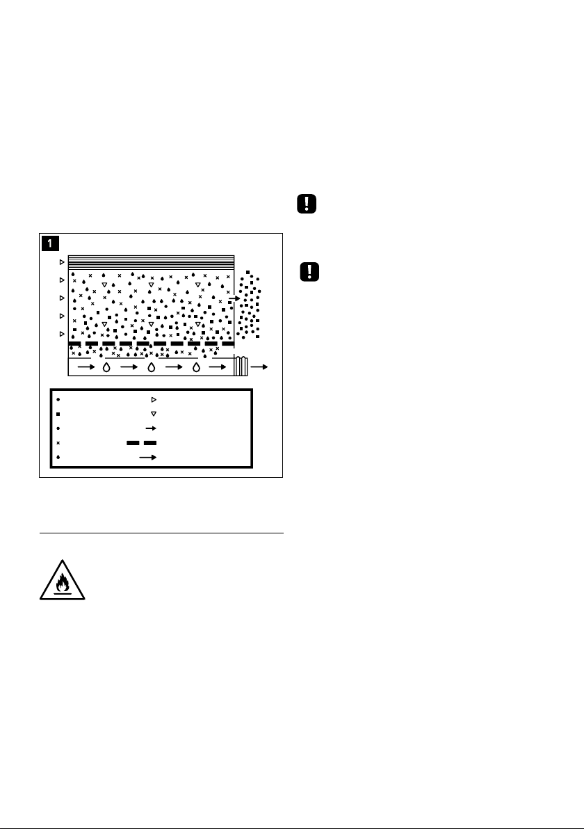
5.3 Basic system operation
In the “Filtration” models, the mains water to be trea-
ted enters the equipment through the turbidity filter
and carbon filter. In this filtration stage, suspended
particles, chlorine, its derivatives and other organic
substances are retained.
In the “Ultrafiltration” models, the water subsequently
passes through the UF membrane where the smallest
particles and even viruses and bacteria will be retained.
In the “Reverse Osmosis” models; The passage of water
into the equipment is controlled by a solenoid valve.
The water, after the filtration stage, is driven towards
the reverse osmosis membrane. Depending on the mo-
del, the equipment may incorporate a pump to increase
the pressure. The pressure of the water on the mem-
brane makes the reverse osmosis process possible.
Subsequently, the water passes through a post-filter
whose purpose is the elimination of possible odors and
salt.
The rejected water or with excess salts and other dis-
solved substances is directed towards the drain for its
elimination.
When demanding water by pressing the front dispensers
of the equipment, the water accumulated in the cold,
hot and reserve water tanks (depending on the model)
flows towards the outlet nozzles.
Attention: There are slight variations in opera-
tion, depending on the model. Read the corres-
ponding section of the Technical Manual.
6. INSTALLATION
The installation of your dispenser must be carried out
by personnel qualified enough for it. Check with the
dealer if in doubt.
Attention: Since the device to be installed impro-
ves the quality of the water that is going to be
consumed, all the tools that are going to be used
for assembly and installation must be clean and in no
case may they be contaminated or impregnated with
grease. oils or oxides. Use exclusive use tools for tube
cutting, membrane manipulation, etc.
Attention: The work must be carried out with an
attitude and adequate hygienic conditions, ta-
king extreme precautions in everything related to ma-
terials and components that are going to be in contact
- Prolonged hyperchlorination over time.
- Sludge or turbidity greater than 3 NTU.
- A concentration of nitrates greater than 100 ppm.
- A sulfate concentration greater than 250 ppm.
- Contact your distributor to recommend the most
suitable pre-treatment for your case, and thus ensure
the proper functioning of the equipment, avoid damage
to components and guarantee the quality of the water
supplied.
4.2 Prior warnings to installation
• In case of having to condition the installation of the
home or business to be able to install the equipment
in the planned place, it must be done following the na-
tional regulations for interior installations of water and
electrical supplies.
• COLUMBIA equipment requires an electrical outlet
less than 1 meter away.
• COLUMBIA equipment should not be installed lying
down or tilted. They must be placed on a flat surface
for correct and safe operation.
• The place planned for its installation must have enou-
gh space for the device itself, its accessories, connec-
tions and for carrying out convenient maintenance.
• Maintain a minimum separation of 10 cm on the sides
and rear wall to ensure proper ventilation of the equi-
pment.
• Under no circumstances will the equipment be insta-
lled outdoors.
Attention: This equipment nust be connected to
the electrical current directly, it must be left to
rest for 2 hours once it has been placed in the
desired installation position. This is very important to
ensure correct system operation, otherwise the com-
pressor could be damaged. The manufacturer will not
be responsible for damages caused to the equipment
in this case.
4.3. Equipment use warnings
• When you are going to be away for more than a week,
close the water inlet tap to the equipment, empty it and
disconnect it from the power supply. When you return,
connect the power supply to it, open the input key and
empty the storage tank twice before consuming water.
Attention: After a prolonged period (more than
a month) in which the equipment has not been
working or producing water, contact your distributor
in order to carry out adequate sanitization and main-
tenance.
Attention: Special attention should be paid to
the cleaning and hygiene of the front dispensers,
on a regular basis and especially when carrying
out periodic maintenance and sanitization. To do this,
use the sanitizing spray and single-use absorbent paper
(See the Sanitization chapter).
Attention: The water provided by the osmosis
equipment is LOW MINERALIZATION. The mine-
ral salts that the human body needs are provided
mainly by food, and to a lesser extent by drinking water.

11
handling of the equipment and corresponding cartrid-
ges. This dust must be removed as it could completely
or partially clog the reverse osmosis membrane, as well
as cause a malfunction of the equipment.
To do this, disconnect the tube that joins the outlet of
the last carbon pre-filter (there may be 1 or 2 depending
on the model) and the inlet to the membrane holder
(See indication A, in the flow chart of the Technical Ma-
nual). Feed the equipment hydraulically (by opening the
inlet valve) and electrically and direct this pipe towards
an external container or sink until the water runs clear
and the coal dust has been completely removed.
Attention: Do not wash the carbon pre-filters
through the front dispensers, as the carbon dust
to be removed would enter the equipment tanks,
and could cause them to malfunction and become dirty
and/or reduction of the useful life of certain compo-
nents.
On RO models; rinse the post-filter, to do so connect
the output of the last carbon pre-filter (there may be
1 or 2 depending on the model) with the inlet of the
post-carbon (See indication B, in the flow chart of the
Technical Manual). Disconnect the post carbon outlet
tube (See indication C, in the flowchart of the Techni-
cal Manual). Feed the equipment hydraulically (by ope-
ning the inlet valve) and electrically and direct this tube
towards an external container or sink until the water
runs clear and the carbon dust from the post-filter has
been completely removed.
After washing the filters, leave all the tubes and compo-
nents in their original position and connections.
8. TIGHTNESS CHECK OF THE SYSTEM, STOP
AND START (RO))
Keep the inlet valve open and keep the equipment
powered by performing a visual inspection of the sys-
tem to ensure that there is no leakage (for about 1 mi-
nute).
9. CLEANING AND MAINTENANCE
9.1 Equipment cleaning
· Always unplug the equipment from the electrical su-
pply before cleaning the equipment.
· Clean the exterior surfaces of the equipment with
a cloth indicative. moistened with water and neutral
soap.
· Never use detergent or chemicals.
· Do not spray water directly on the surface of the equi-
pment.
· If the condenser accumulates dust or other unknown
substances, clean it with a cloth moistened with water
and neutral soap.
· After cleaning the equipment, dry it completely before
connecting it to the power supply.
with the water to be treated or consumed.
Attention: Avoid the risks of external contamina-
tion of the equipment due to improper handling,
using gloves, hand sanitizing gel or washing your
hands as many times as necessary throughout the ins-
tallation, start-up and maintenance of the equipment.
Install the drain collar, only in the RO version (image 2)
and the inlet adapter (image 3) and connect them to the
respective connectors of the IN (input) and OUT / DRA-
IN (drain) equipment, only in the RO version (image 4).
The drain pipe can be directed up a maximum of 2.5
meters vertically and another 5 meters horizontally.
Some models include a connection for emptying from
the drip tray (see the Technical Manual), in this case this
tube must be directed to a drain that is at a lower hei-
ght than the tray since it will empty due to the weight
of water.
Attention: Some of the installation accessories
may vary depending on the model and region in
which the equipment is distributed.
Use the appropriate tools and sealants to ensure the
tightness of the connections.
7. RINSING THE CARBON FILTERS
See chapter 6 of the Technical Manual to see how to
access the filters.
It is necessary to remove the granulated carbon dust
from the filters that is generated during transport and
40mm Drain Clamp
Inlet valve and adapter
2
3
4

Data sheet
Change the filters properly, depending on the model of
the equipment and the type of filter. Ensure the tight-
ness of the joints and the original hydraulic configura-
tion of the system. See the Technical Manual for the ne-
cessary filters according to your equipment model and
how to access the filters.
Sanitize the equipment following the indications des-
cribed in the Sanitization Procedure.
Attention: In case of detecting that the water
dispensed does not comply with current national
legislation, close the input key of the equipment,
empty it through the tap, disconnect it electrically and
contact your technical service.
10. SANITIZATION PROCEDURE
Necessary material:
• Manual valve.
• Dosing cartridge with connectors.
• Hydrogen peroxide (0.5 l). (sanitizing product)
• Single-use vinyl gloves.
• Hydrogen peroxide detector strips.
• Sanitizing spray. (Hydrogen peroxide)
• Paper napkin.
Perform a sanitization of the equipment during start-
up, when appropriate (every time there is a risk of con-
tamination of the equipment by handling components
in contact with water) or with the indicated periodicity.
To do this, follow the steps below:
Attention: The water used during sanitization
must be potable water (from a public distribu-
tion network, complying with the corresponding
potability requirements of RD 140 / 2003, European
directive 98 / 83 or current local legislation).
• Keep the inlet valve closed (6) and empty the accumu-
lation tank through the front dispensers (see chapter
“how to extract water”).
• Sanitization must be carried out with the new pre- and
post-filters installed and properly rinsed beforehand,
correctly removing carbon dust from them.
• Use single-use vinyl gloves to handle sanitizing pro-
ducts.
10.1 Sanitizing the pre-filters and membrane
Insert the dosing cartridge into the equipment inlet
· Daily empty the drip tray.
9.2 Water treatment maintenance
Attention: Some components of your equipment,
such as pre-filters, membranes and post-filters
(depending on the model), are consumables that
have a limited duration. The duration will depend on
the quality of the local water, consumption, type of use
and specific aspects of the water to be treated such as
extreme turbidity, high chlorination, excess iron.
Attention: In order to guarantee the quality of
the water supplied by your equipment, periodic
maintenance must be carried out.
* Depending on the intended use and characteristics of
the water to be treated.
Maintenance must be carried out by trained personnel,
who must handle the equipment properly, as well as
use original spare parts to maintain the characteristics,
warranty, certifications and benefits of the equipment
and thus preserve the quality of the water dispensed.
Attention: The use of non-original spare parts,
installation outside the operating limits and im-
proper start-up, maintenance or use, may lead
to the loss of the guarantee, as well as the invalidation
of the certifications to which the equipment has been
subjected.
An excess in any compound (total chlorine, turbidity,
hardness, etc.) can cause a reduction in the life of fil-
ters and certain components. These maintenances are
indicative.
Attention: All consumables are delivered with in-
dividual packaging specially designed to guaran-
tee hygienic conditions of storage and transport.
Take extreme hygienic precautions after removing the
consumables from their packaging and when handling
the various connectors and components.
Attention: Before disassembling the equipment,
plan all the material you will need to carry out
the maintenance operations and the necessary
space for it. Work in a properly lit place, in suitable hy-
gienic conditions and with enough space to carry out
operations comfortably.
Recommended maintenance
· Sediment pre-filter: At least every 12 months*
· Carbon pre-filter: At least every 12 months*
· Osmosis membrane: Every 3 years approx. (for soft
water to be treated (hardness >15ºHF)))
· Postfilter: At least every 12 months*
· Sanitization: At start up. At least every 12 months
based on usage. Every time you access components in
contact with water from the equipment or do not
have consumed water for more than a month.
6
CLOSED

13
tube.
For it:
• Disconnect the inlet pipe to the equipment marked
“IN”, and insert the dosing cartridge between the inlet
valve and the water inlet of the equipment (8). For grea-
ter comfort and ease of access during sanitization and
the opening and closing operations of the inlet valve,
you can insert, together with the sanitizing dosing car-
tridge, a manual valve in the closed position, which will
perform the same functions as the inlet valve.
• Once the assembly is installed, keep the new inlet val-
ve closed and open the inlet valve (9). The dosing cartri-
dge should initially be empty.
• Pour 100 ml of sanitizing product into the dosing car-
tridge inserted in the equipment inlet (10). Screw the
glass correctly to its head.
• On RO models. Connect the equipment to the power
supply.
• Open the water inlet valve to the equipment, allowing
it to start working and allowing the sanitizing product
to be pushed towards it. Keep the inlet valve in that
position and let the equipment run for 10 minutes for
reverse osmosis models and 3 minutes for Filtration and
Ultrafiltration models.
• Close the inlet valve (11) and unplug the equipment
from the electrical supply, wait for the equipment to
stop pouring water through the rejection outlet towards
the drain (reverse osmosis models only).
• Let the filters soaked with the Product rest for 20 mi-
nutes. Meanwhile proceed to sanitize the deposits.
10.2 Sanitization of tanks and front dispenser
• Sanitize the nozzles of the front dispensers using cot-
ton swabs and sanitizing spray.
• Completely empty the deposits through the front dis-
pensers and purge outlet (12). Refill the tanks and empty
them to rinse the sanitizing product remains.
• Remove the complementary elements used for Sani-
tization and reconnect the power tube to the input (IN)
of the equipment.
• Open the inlet valve and electrically feed the equip-
ment so that it starts up.
• Use the sanitizing product detection strips (318701) to
verify that the equipment is properly rinsed, make the
necessary empties in case of detecting sanitizing pro-
duct remains.
11. INTERFACE WITH THE USER
Attention: Depending on the model, the equip-
ment may incorporate an electronic controller
that will efficiently manage the functionality and
status indications in which it is located, as well as the
different security systems.
If it is incorporated, see points 3 and 4 of the equip-
ment’s Technical Manual where the states in which each
system can be found and the information provided by
it are described.
CERRADA
8
AGUA
OXIGENADA
10
CERRADA
11
CERRADA
ABIERTA
9
CLOSED
CLOSED
CLOSED
OPEN

Data sheet
THE TANK IS NOT FILLED AT ALL
Problem
1. No water enters the dispenser
2. Water enters the dispenser,
but does not reach the membrane
3. The solenoid valve does not open
4. The solenoid valve and
the pump do not work
5. The solenoid valve opens,
but the pump does not work
6. The level switch does not work
7. Production is low
8. The membrane is clogged
Cause
The inlet valve is closed
The dispenser is unplugged
The switch is OFF
No water supply
Obstruction in the feeding tube
to the dispenser
Solenoid valve does not open
There is a clogged filter
No power to the solenoid valve
The solenoid valve is damaged, sin-
ce current reaches it and it does
not open (Check with a voltmeter)
Level switch does not working
Cable is disconnected
Pump is damaged
It is damaged and does not respond
to raising and lowering the float
The electronic card is damaged
Partial clogging of the sediment
filter, comparing the inlet flow rate
with the outlet flow rate of the se-
diment cartridge
Partial obstruction of the solenoid
valve, comparing the inlet flow rate
with the outlet flow rate of the so-
lenoid valve
The membrane is clogged
The equipment does not
reject water
The membrane is more than 3 years
old
The TDS of the inlet water is greater
than 1500 ppm
Solution
Open the inlet valve
Plug the dispenser into the mains
Position the switch to ON
Non-dispenser problem
Change the feeding tube
See point 3
Disconnect the output of each fil-
ter one by one to locate the clog-
ged filter and replace it
The tank is full and there is no de-
mand for water
Replace the solenoid valve
See point 6
Check that there are no loose wires
Change the pump
Change the level switch
Change the electronic card
Change the sediment filter
Change solenoid valve
See point 8
Change flow restrictor and mem-
brane
Change membrane
Contact your service representa-
tive
PRODUCTION IS LITTLE
12. . SOLUTION OF PROBLEMS

15
WATER DOES NOT STOP COMING OUT OF THE DRAIN
WATER QUALITY IS NOT GOOD
LA FUENTE NO ENFRÍA O SALE POCA AGUA FRÍA
THE DISPENSER DOES NOT HEAT OR LITTLE HOT WATER COMES OUT
9. The dispenser never stops
pouring water down the drain
10. The water quality is not correct
11. The water tastes bad
12. The water does not
come out cold
13. The water does not
come out hot
The level switch does not respond
to the full tank command (Check
with a voltmeter)
The inlet solenoid valve has stuck
since it does not close when the
electrical current is disconnected
The rejection flow is much less than
0.5 liters per minute
The membrane has reached the
end of its useful life and no longer
removes 90% of the salts from the
inlet water
The taste is like bitter, metallic or
plastic and the output TDS is less
than 25
The dispenser is contaminated
The rear switch (COLD) is in the OFF
position
The customer takes out bottles of
cold water and empties the cold
water tank
The cold system is damaged or the
refrigerant gas has been lost
The rear switch (HOT) is in the OFF
position
The hot tank thermostat is dama-
ged
The resistance is damaged
Cambiar el interruptor de nivel.
Cambie la electroválvula de entra-
da.
Reemplace el restrictor de caudal
de rechazo
Cambie la membrana.
Reemplace el postfiltro por un car-
tucho remineralizador.
Realice una higienización completa
de la fuente.
Pulse el interruptor a ON.
Las fuentes están diseñadas para
que se saque el agua vaso a vaso.
Retire la fuente para su reparación
en taller.
Push the switch to ON
Change the thermostat of the hot
tank
Change the resistance

Data sheet
1. TECHNICAL CHARACTERISTICS
APPLICATION
ROP Model (Reverse Osmosis)
F Models (Filtration)
UF (Ultrafiltration) models
Use
Improvement of the characteristics of drinking water (that complies with the requirements of the European Direc-
tive on water for human consumption 98/83 or its national transpositions in the different member states of the
European Community).
Modifications due to reduction or contribution
Model ROP
• Water treatment by reverse osmosis is capable of reducing the concentration of salts and other substances in
high percentages.
• Minimal reduction* of certain compounds and parameters:
Sodium – 90 %
Calcium – 90%
Sulphate – 90%
Chloride – 90%
Total hardness – 90%
Conductivity – 90%
(*) Depending on the characteristics of the water to be treated (at the membrane outlet). These values may vary
depending on the type of postfilter that the equipment incorporates.
Model F
• Water treatment by filtration retains suspended particles with a diameter greater than 5 microns.
• The carbon filter reduces* the taste and odor of the water, as well as organic components.
(*) Depending on the characteristics of the water to be treated.
Modelo UF
• These equipments consist of a first stage of Filtration.
• Ultrafiltration water treatment is capable of retaining suspended particles with a diameter between 0.1 and 0.001
microns.
(*) Depending on the characteristics of the water to be treated.
WORKING LIMITS
Pressure (max. / min.)
TDS (máx.)
Temperature (max. / min.)
Hardnes (max.)
ROP
2,5 bar (250 kPa)
1 bar (100 kPa)
2000 ppm
40ºC - 2ºC
15ºHF**
UF
5 bar (500 kPa)
1 bar (100 kPa)
-
40ºC - 2ºC
-
F
5 bar (500 kPa)
1 bar (100 kPa)
-
40ºC - 2ºC
-
TECHNICAL DATA
Control type:
Security system:
Inlet connection:
Drain connection:
Wall adapter:
Drain collar:
ROP
Level switch.
Inlet solenoid valve. Cold
water thermostat.
Hot water thermostat.
Hot water thermal safety
protector
1/4”
1/4”
1/2”
40mm drain pipe clamp
F
Cold water thermostat.
Hot water thermostat.
Hot water thermal safety
protector
1/4”
-
1/2”
-
UF
Cold water thermostat.
Hot water thermostat.
Hot water thermal safety
protector
1/4”
-
1/2”
-

17
TECHNICAL DATA
A
C
B
ROP
1 sediment prefilter
2 GAC prefilters
1 BLOCK prefilter
1 RO 50 GPD membrane
1 carbon postfilter
F
1 sediment prefilter
1 carbon prefilter
UF
1 sediment prefilter
1 carbon prefilter
1 ultrafiltration prefilter
1 carbon prefilter
Treatment
Dimmensions:
Weight:
TANKS TOTAL VOLUME
Cold water tank:
Hot water tank:
Power supply
REFRIGERATION SYSTEM
Compressor:
Compressor power:
Condenser:
Refrigerant gas:
Temperature control:
HEATING SYSTEM
Heater:
Heater power:
Temperature control:
Protección sobrecalentamiento:
(A x B x C) 1115 x 300 x 390 mm
18 kg
5 liters total volume
2 liters
220 – 240 Vac
1/10 CV sealed
85 W
Capillarytype
R600a
Adjustable thermostat
Band
500 W
Termostato Bimetal
Bi-metal auto-armable
ROP MODEL HYDRAULICAL DIAGRAM
PRESSURE REDUCER
INLET SOLENOID
VALVE PUMP
INLET
SEDIMENT FILTER
CA RBONFILT ER
CA RBONFILT ER
RO MEMBRANE
CARBON POSTFILTER
DRAIN
RESTRICTOR
HOT WATER TANK DRAIN
HOT WATER OUTLET
AMBIENT WATER OUTLET
COLD WATER OUTLET
COLD WATER TANK
FLOAT VALVE

Data sheet
ROP MODEL HYDRAULICAL DIAGRAM
F MODEL HYDRAULIC DIAGRAM
SEDIMENT FILTER
PRESSURE REDUCER
CA RBONFILT ER
MEMBRANA UF
POSTCARBONFILTER
HOT WATER TANK DRAIN
HOT WATER TANK
HOT WATER OUTLET
AMBIENT WATER OUTLET
COLD WATER OUTLET
COLD WATER TANK
FLOAT VALVE
SEDIMENT FILTER
PRESSURE REDUCER
CA RBONFILT ER
HOT WATER TANK DRAIN
HOT WATER TANK
INLET
HOT WATER OUTLET
AMBIENT WATER OUTLET
COLD WATER OUTLET
COLD WATER TANK
FLOAT VALVE

19
ROP MODEL ELECTRICAL DIAGRAM
F/UF MODEL ELECTRICAL DIAGRAM
PTC
PTC
L
L
E
E
N
N
COOLING SYSTEM SWITCH
TEMPERATURE CONTROL II
TEMPERATURE
CONTROL II
TEMPERATURE
CONTROL II
TRANSFORMER
PUMP
COLD THERMOSTAT
COLD THERMOSTAT
COMPRESSSOR
COMPRESSSOR
HEATER
HEATER
LED 1
LED 1
LED 2
LED 2
LED 3
LED 3
BLUE
BLUE
INLET SOLENOID VALVE
HEATING SYSTEM SWITCH

Data sheet
HYDRAULIC CONNECTION DIAGRAM ROP MODEL
HYDRAULIC CONNECTION DIAGRAM F/UF MODEL
INLET
DRAIN
INLET
This manual suits for next models
2
Table of contents
Other Columbia Water Dispenser manuals
Popular Water Dispenser manuals by other brands

Bunn
Bunn H5E Specifications

Quench
Quench 730 instructions

Haws
Haws H1011.8 Installation, operation & maintenance instructions

Whirlpool
Whirlpool Hot water dispenser Installation instructions and use and care guide

SMARDY
SMARDY YR100-A instruction manual

Elkay
Elkay EZTL EZSTL8 1D Series Installation, care & use manual