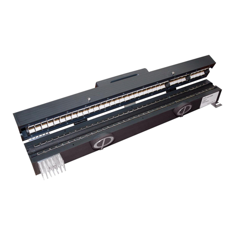
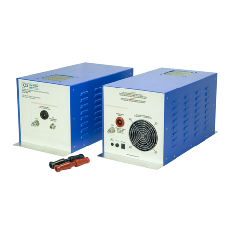
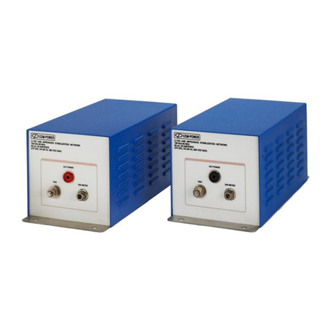
COM-power corporation T-Series User manual

Page1of12
INSTRUCTIONMANUAL
ShieldedT‐seriesCoupling/DecouplingNetworks(CDN)
19121ElToroRd●Silverado,California92676●(949)459‐9600●com‐power.com
REV021215
INSTRUCTIONMANUAL
ShieldedT‐seriesCOUPLING/DECOUPLING
NETWORKS(CDN)
CDN‐T8SE
150kHzto230MHz

Page2of12
INSTRUCTIONMANUAL
ShieldedT‐seriesCoupling/DecouplingNetworks(CDN)
19121ElToroRd●Silverado,California92676●(949)459‐9600●com‐power.com
REV021215
TableofContents
1.0Introduction..............................................................................................................3
2.0ProductSpecifications..............................................................................................4
2.1OtherequipmentavailablefromCom‐Power...........................................................4
3.0ImportantSafetyPrecautions..................................................................................5
3.1MaximumRFinput........................................................................................................5
4.0Warranty...................................................................................................................6
4.1Maintenance.................................................................................................................6
5.0CDNRequirements....................................................................................................7
5.1Overview........................................................................................................................7
5.2CDNParameters.............................................................................................................7
5.2.1CommonModeImpedance......................................................................................................7
5.2.2VoltageDivisionFactor............................................................................................................7
5.2.3CouplingFactor........................................................................................................................7
5.3CalibrationAccessories................................................................................................8
6.0CalibratingtheTestLevelsandRunningtheTest....................................................8
6.1TestLevels.....................................................................................................................8
6.1.1CDNSelection.........................................................................................................................9
6.2TestLevelCalibration..................................................................................................10
6.2.1AutomatingthecalibrationandrunningtestusingCSAT.....................................................10
6.3RunningtheTest...........................................................................................................11
7.0TypicalPerformanceData.......................................................................................12
Figure3‐Impedancec0mparedtoCISPR16‐1‐2edition1.2&IEC61000‐4‐6requirements.................12
Figure4‐PhasecomparedtoCISPR16‐1‐2edition1.2&IEC61000‐4‐6requirements.........................12

Page3of12
INSTRUCTIONMANUAL
ShieldedT‐seriesCoupling/DecouplingNetworks(CDN)
19121ElToroRd●Silverado,California92676●(949)459‐9600●com‐power.com
REV021215
1.0Introduction
Thismanualincludesproductspecifications,safetyprecautions,productmaintenanceand
warrantyinformation.Italsoincludessomebasicguidanceonproperlyconfiguring
calibration,testsetup,runningtestlevelcalibrationsandperformingconductedimmunity
testing.
InformationcontainedinthismanualisthepropertyofCom‐PowerCorporation.Itisissued
withtheunderstandingthatnoneofthematerialmaybereproducedorcopiedwithout
permissionfromCom‐Power.

Page4of12
INSTRUCTIONMANUAL
ShieldedT‐seriesCoupling/DecouplingNetworks(CDN)
19121ElToroRd●Silverado,California92676●(949)459‐9600●com‐power.com
REV021215
2.0ProductSpecifications
ModelsCovered: CDN‐T8SE
FrequencyRange: 150kHzto230MHz
I/OratingforEUT/AEports: 100VAC,150VDC,1A(Max)
Numberofbalancedlines: 8
Maxcurrentrating:
Commonmodeimpedance
150kHz‐26MHz: 150Ω±20Ω
26MHz‐80MHz: 150Ω+60Ω/–45Ω
80MHz‐230MHz: 150Ω+60Ω/–60Ω
MaximumRFvoltageinput:
Voltagedivisionfactor(RFtoEUTport):9.5dB+4/‐1dB
I/Oconnections:ShieldedRJ45
RF(Disturbancecoupling)connector: BNC(f)50Ω
DimensionsLxWxH(inches/cm):
Weight:5lbs/2.3kg(maxweightallmodels)
OperatingTemperature: 5°Cto40°C/40°Fto104°F
Thisequipmentisdesignedforindooruseonly.
2.1OtherequipmentavailablefromCom‐Power.
• ADA‐515‐150Ωto50Ωadapter
• TEP‐050‐50Ωterminator
• ADA‐T4SE/ADA‐T8SE‐ShortingAdapters
• DCD‐1000‐100W‐DualDirectionalCoupler,100kHz–1000MHz
• DCU‐300‐100W‐UniDirectionalCoupler,100kHz–300MHz
• ATTN‐X‐100W‐Attenuator,DCto1GHz
• ACS‐250‐25W‐25WattPowerAmplifier,150kHz–250MHz
• ACS‐250‐50W‐50WattPowerAmplifier,150kHz–250MHz
• ACS‐250‐100W‐100WattPowerAmplifier,150kHz–250MHz
• CSAT(Ver‐XX)‐ConductedImmunityAutomatedTestSoftware.

Page5of12
INSTRUCTIONMANUAL
ShieldedT‐seriesCoupling/DecouplingNetworks(CDN)
19121ElToroRd●Silverado,California92676●(949)459‐9600●com‐power.com
REV021215
3.0 ImportantSafetyPrecautions
TheCDNmustbesecurelyfastenedtotheearthgroundbeforemakinganyconnectionsto
externalpower.PropergroundingoftheCDNisrequiredinordertopreventhighleakage
currentsfrompresentingapotentialsafetyhazardfortestpersonnel.Tohelpestablish
propergrounding,thebottomsurfaceoftheCDNisunpainted.Inaddition,thebottomplate
hasmountingholesforsecurelyboltingtheCDNtoagroundplane.Ifpropergroundinghas
beenachieved,theresistancemeasuredbetweentheCDNbottomplateandtheground
planeshouldbelessthan10milliohms.
DonotconnectthepowertotheCDNsuntilallthetestequipmentandEUTareinplaceand
electricallyconnected.Avoidhavinganyexposedlivewiresorconnections.Youcanusethe
followingprocedure.
1. ConnectEUTcabletoCDNEUTport.
2. ConnecttheTestGenerator(signalgenerator,poweramplifier,attenuators,etc)to
theRFportoftheCDN.Thetestgeneratoroutputmustremaindisableduntilall
connectionsaremade.
3. Connectaccessoryequipment(AE)port.
3.1MaximumRFinput
DonotexceedRFinputleveltotheCDN.ExcessiveRFinputwilldamagetheCDNinputand
willnotbecoveredunderwarranty.Toavoidaccidentaldamagetothepoweramplifieror
CDN,disabletheRFoutputofpoweramplifierbeforemakinganyconnections.Alsomake
surethesignalgeneratoroutputissettoitsminimumlevelwhentheRFisturnedon.

Page6of12
INSTRUCTIONMANUAL
ShieldedT‐seriesCoupling/DecouplingNetworks(CDN)
19121ElToroRd●Silverado,California92676●(949)459‐9600●com‐power.com
REV021215
4.0 Warranty
Com‐PowerwarrantstoitsCustomersthattheproductsitmanufactureswillbefreefrom
defectsinmaterialsandworkmanshipforaperiodof3years.Thiswarrantyshallnotapplyto:
• Transportdamagesduringshipmentfromyourplant.
• Damagesduetopoorpackaging.
• Productsoperatedoutsidetheirspecifications.
• ProductsImproperlymaintainedormodified.
• Consumableitemssuchasfuses,powercords,cables,etc.
• Normalwear
• Calibration
• ProductsshippedoutsidetheUnitedStateswithoutthepriorknowlegeofCom‐
Power.
Inaddition,Com‐Powershallnotbeobligedtoprovideserviceunderthiswarrantytorepair
damageresultingfromattemptstoinstall,repair,serviceormodifytheinstrumentby
personnelotherthanCom‐Powerservicerepresentatives.
UndernocircumstancesdoesCom‐Powerrecognizeorassumeliabilityforanyloss,damage
orexpensearising,eitherdirectlyorindirectly,fromtheuseorhandlingofthisproduct,or
anyinabilitytousethisproductseperatelyorincombinationwithanyotherequipment.
Whenrequestingwarrantyservices,itisrecommendedthattheoriginalpackagingmaterial
beusedforshipping.Damageduetoimproperpackagingwillvoidwarranty.
Inthecaseofrepairorcomplaint,alabelshouldbeattachedtothehousingofthe
instrumentwhichdescribesbrieflythefaultsobserved.Pleaseincludethename,telephone
numberandemailaddressofthecontactperson.Pleasevisitourwebsitewww.com‐
power.comandobtainanRMAnumberbyselectingserviceandcompletingtheonlineform.
4.1Maintenance
Thisproductcontainnouserserviceablepartsinside.Iftheunitdoesnotoperateorneeds
calibration,pleasecontactCom‐PowerCorporation.Donotinstrumentcover.Any
modificationsorrepairsperformedontheunitbysomeoneotherthananauthorizedfactory
trainedtechnicianwillvoidwarranty.
Theexteriorsurfacemaybecleanedwithmilddetergentandthenbewipedwithadry,clean,
lint‐freecloth.Usecaretoavoidliquidsorotherforeignobjectsenteringthechassis.

Page7of12
INSTRUCTIONMANUAL
ShieldedT‐seriesCoupling/DecouplingNetworks(CDN)
19121ElToroRd●Silverado,California92676●(949)459‐9600●com‐power.com
REV021215
5.0 CDNRequirements
5.1Overview
Com‐PowershieldedCDN‐TseriesCoupling/DecouplingNetworksaredesignedspecifically
forconductedimmunitytestingperIEC61000‐4‐6.
TheshieldedCDN‐Tseriesisusedforshieldedethernetlines10/100/1000mbps.
TheseCDNs
•ProvideameansofcouplingRFcommonmodesignalstotheabovelinetypes.
•Providetherequiredcommonmodeimpedancebetweenthetheselinesandground
necessaryforproperperformanceofthetesting.impedancetotheequipmentunder
testindependentoftheauxillaryequipmentcommonmodeimpedance.
•Minimizeinterferencetotheauxillaryequipmentviacommonmodedecouplingof
thedisturbingsignals.
•ProvideuninterruptedcommuninicationbetweentheEUTandauxillaryequipment.
TheCom‐PowershieldedCDNTseriesfullycomplywiththerequirementcontainedintheIEC
61000‐4‐6andCISPR16‐1‐2.
5.2CDNParameters
5.2.1 CommonModeImpedance
Commonmodeimpedanceisdefinedasthe“ratioofcommonmodevoltageandcommon
modecurrentatacertainpoint“.ThecommonmodeimpedancerequirementsforaCDN
mustbemetwithCDNauxillaryequipmentinputpowerterminalsopenorshortcircuitedto
ground.
5.2.2VoltageDivisionFactor
VoltagedivisionfactoristheamountofvoltagethatislostbetweentheRFinputterminalof
theCDNandtheEUTportandismeasuredthrougha150Ω to50Ω adapter(ADA‐515)
connectedtotheEUTport.
5.2.3CouplingFactor
TheCDNcouplingfactorisdefinedastheratiogivenbytheopencircuitvoltage(e.m.f)
obtainedattheEUTportofthecoupling(anddecoupling)devicedividedbytheopencircuit
voltageobtainedatthetestgenerator.

Page8of12
INSTRUCTIONMANUAL
ShieldedT‐seriesCoupling/DecouplingNetworks(CDN)
19121ElToroRd●Silverado,California92676●(949)459‐9600●com‐power.com
REV021215
5.3CalibrationAccessories
ThefollowingaccessoriesareavailablefortheCDNverificationoftheparametersaboveand
forthelevelsettingcalibrationdescribedherein.
• Shortingadapters(PartADA‐T4SE/ADA‐T8SE)
• 150Ω–50Ωadapters(Part#ADA‐515)
• 50Ωterminator(Part#TEP‐050)
6.0CalibratingtheTestLevelsandRunningtheTest
6.1 TestLevels
Table1:RequiredtestlevelsperIEC‐61000‐4‐6
Vo
Volts
Vo
dBµV
Vo
dBm
Umr(150)
Volts
Umr(150)
dBµV
Umr(150)
dBm
1120130.167104.5‐2.5
2130230.51147
3140331.67124.517.5
Vo=Opencircuitvoltagein150Ωsystem
Umr=Voltagelevelmeasuredattheoutputofthe150Ωto50Ωadapter(ADA‐515)

Page9of12
INSTRUCTIONMANUAL
ShieldedT‐seriesCoupling/DecouplingNetworks(CDN)
19121ElToroRd●Silverado,California92676●(949)459‐9600●com‐power.com
REV021215
6.1.1 CDNSelection
TheIEC‐61000‐4‐6requiresthatanappropriatecouplingdecouplingnetworks(CDN)with
definedcommonmodeimpedancebeusedforcouplingand/ordecouplingpurposesonany
typeofpowerorI/OinterfaceforwhichaCDNissuitableandavailable.TheshieldedTseries
CDNsareonlyappropriateforsignallines(ethernet).OthertypesCDNsavailablefromCom‐
PowerCorporationaregivenbelow.
ModelSpecifications
CDN‐M125ESingleline,25Amp,150kHz‐230MHz
CDN‐M225ESingleline+Neutral,25Amp,150kHz‐230MHz
CDN‐M325ESingleline+Neutral+Earth,25Amp,150kHz‐230MHz
CDN‐M425EThreephase+Neutral,25Amp,150kHz‐230MHz
CDN‐M525EThreephase+Neutral+Earth,25Amp,150kHz‐230MHz
CDN‐C50E50Ohmcoaxcable,150kHz‐230MHz
CDN‐C75E75Ohmcoaxcable,150kHz‐230MHz
CDN‐S1Shieldedcablewith1conductor,150kHz‐80MHz
CDN‐S2Shieldedcablewith2conductors,150kHz‐80MHz
CDN‐S4Shieldedcablewith4conductors,150kHz‐80MHz
CDN‐S9Shieldedcablewith9conductors,150kHz‐80MHz
CDN‐S15Shieldedcablewith15conductors,150kHz‐80MHz
CDN‐S25Shieldedcablewith25conductors,150kHz‐80MHz
CDN‐AF2EUnshieldedcablewith2conductors,150kHz‐230MHz
CDN‐AF4EUnshieldedcablewith4conductors,150kHz‐230MHz
CDN‐AF8EUnshieldedcablewith8conductors,150kHz‐230MHz
CDN‐T2EUnshieldedcablewith2conductorsbalancedpairs,150kHz‐230MHz
CDN‐T4EUnshieldedcablewith4conductorsbalancedpairs,150kHz‐230MHz
CDN‐T8EUnshieldedcablewith8conductorsbalancepairs,150kHz‐230MHz

Page10of12
INSTRUCTIONMANUAL
ShieldedT‐seriesCoupling/DecouplingNetworks(CDN)
19121ElToroRd●Silverado,California92676●(949)459‐9600●com‐power.com
REV021215
6.2TestLevelCalibration
BeforeyoubegintestingwiththeCDNyouwillneedtoestablishacalibrateddrivelevels
correspondingtoyourdesiredtestlevels.DuringdrivelevelcalibrationtheRFsignallevel
beinginjectedtotheCDNisadjustedincrementallyuntilthevoltagelevelmeasuredatthe
150Ω to50Ω adapterconnectedtotheEUTportisapproximatelyequaltotheUmr(150)
valuegivenintable1,andthessignalgeneratoroutput,orforwardpowerdeliveredtothe
CDNisrecorded.Thisprocessisthenrepeatedateachfrequencystartingat150kHzwith
stepsizesnogreaterthan1%oftheprecedingfrequencyvalueupto80or230MHz.This
equatesto633discretetestfrequencypointsupto80MHzand739pointsupto230MHz.
Recordthesignalgeneratoroutputateachfrequency.Typicaltestlevelcalibrationsetupis
showninfigure1below.
6.2.1 AutomatingthecalibrationandrunningtestusingCSAT.
Theentirecalibrationandprocessdescribedabovecanbeperformedmanually,butitisvery
timeconsumingandtediusprocess.ThisprocesscanbecanbeautomatedusingtheCSAT
softwareavailablefromCom‐Power.PleasecallCom‐Powerformoreinformation.
Figure1:TypicalTestlevelcalibrationsetup
AOptionalPCRunningCSATSoftware GCDN‐MT4SE/CDN‐T8SE
BSignalGeneratorHShortingadapters
–
ADA‐T4SE,ADA‐T8SE
CPowerAmplifier(ASC‐series)IADA‐515
–
150Ωto50Ωadapters
D6dBPowerAttenuatorJPowerAttenuator(ATTN‐30‐100W)
EOptionalPowermeterKSpectrumanalyzer/PowerMeter
FOptionalDirectionalCoupler(DCUor
DCDseries)
I
A
D
RF OUT
C
G
RFIN
AUXEUT
E
K
F
J
BRF IN
50Ω
IN
H
Groundplane
MONITOR
PORT
IN
RFIN
OUT
RF OUT

Page11of12
INSTRUCTIONMANUAL
ShieldedT‐seriesCoupling/DecouplingNetworks(CDN)
19121ElToroRd●Silverado,California92676●(949)459‐9600●com‐power.com
REV021215
6.3 RunningtheTest
Pleasereadsafetyprecautionsinthismanualbeforeproceeding.Thediagrambelowisthe
typicaltestsetupformakingconductingimmunitytestingusingtheCDN.Thesignal
generatoroutputlevelsrecordedduringthetestlevelcalibrationarenowusedtoperform
thetesting.Duringthetesthowever,thesignalgeneratoroutputisusuallymodulated.Refer
totheapplicableproductfamilystandard,productenvironmentstandardforyourproduct
(whicheverisapplicable)todeterminethemodulationtypeandotherspecifictest
requirementappropriateforyourproduct.AlsorefertoIEC61000‐4‐6forgeneraldetails
suchastestsetupandtestprocedures.Thesedetailsarebeyondthescopeofthismanual.
Figure2:TypicalTestSetup
AOptionalPCRunningCSATSoftware FOptionalDirectionalCoupler(DCUorDCDseries)
BSignalGeneratorGCDN‐T4SE,CDN‐T8SE
CPowerAmplifier(ASC‐series)HPowerSupply
D6dBPowerAttenuatorIEquipmentundertest
EOptionalPowermeter
A
D
RF OUT
C
G
RFIN
AUXEUT
E
F
I
B
H
RF IN
Groundplane
MONITOR
PORT
IN
RFIN
OUT
RF OUT

Page12of12
INSTRUCTIONMANUAL
ShieldedT‐seriesCoupling/DecouplingNetworks(CDN)
19121ElToroRd●Silverado,California92676●(949)459‐9600●com‐power.com
REV021215
7.0TypicalPerformanceData
Figure3‐Impedancec0mparedtoCISPR16‐1‐2edition1.2&IEC61000‐4‐6
requirements.
Figure4‐PhasecomparedtoCISPR16‐1‐2edition1.2requirements.
60
80
100
120
140
160
180
200
220
240
0.1 1 10 100 1000
Impedance(Ω)
Frequency(MHz)
‐40
‐30
‐20
‐10
0
10
20
30
40
0.1 1 10 100
Phase(deg)
Frequency(MHz)
This manual suits for next models
1
Table of contents
Other COM-power corporation Test Equipment manuals