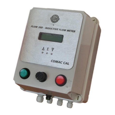
COMAC CAL FLOW 38Imp Batch User manual

Technical and installation
manual FLOW 38 Batch (impulse) Page 1 (total 26) COMAC CAL s.r.o.
FLOW 38Imp Batch
Ver.8.24
(Impusle input)
Instalation and technical manual
Date of publish 27/05/2021

Technical and installation
manual FLOW 38 Batch (impulse) Page 2 (total 26) COMAC CAL s.r.o.
Content:
Warranty..................................................................................................................................................4
Wiring ......................................................................................................................................................4
Important information ...........................................................................................................................4
Installation of the meter's detached evaluation unit............................................................................5
Meter wiring of batching unit ...............................................................................................................6
Meter wiring of sensor..........................................................................................................................7
Electrical connection of the meter ........................................................................................................7
Impuls output ........................................................................................................................................8
Buttons START, STOP.........................................................................................................................9
Controlling of the batching valve..........................................................................................................9
Data output............................................................................................................................................9
Protection degree...................................................................................................................................9
Replacement of tube fuse in the meter..................................................................................................9
Wiring check.......................................................................................................................................10
Putting into operation..........................................................................................................................10
Flow 38 Batch operating instructions..................................................................................................12
Procedure to set individual menu items:.............................................................................................14
Date and time......................................................................................................................................15
Operation time counter........................................................................................................................15
Power loss counter..............................................................................................................................15
Impulse output / flow switch...............................................................................................................16
Impulse output.....................................................................................................................................16
Flow switch.........................................................................................................................................16
Setting of the range of dose.................................................................................................................17
Communication...................................................................................................................................17
Idle state basic indications on display.................................................................................................18
Display dimming.................................................................................................................................19
Display backlight ................................................................................................................................19
Serial number......................................................................................................................................19
Impulse constant of external sensor....................................................................................................19
Empty tube test....................................................................................................................................19
Firmware version ................................................................................................................................20
Dead band – measurement start suppression ......................................................................................20
Zero calibration...................................................................................................................................20
Flow simulation...................................................................................................................................21
Language.............................................................................................................................................21

Technical and installation
manual FLOW 38 Batch (impulse) Page 3 (total 26) COMAC CAL s.r.o.
Counter resetting.................................................................................................................................21
Nominal diameter (DN)......................................................................................................................21

Flow direction.....................................................................................................................................22
Flow units displayed [Q].....................................................................................................................22
Volume units displayed [V]................................................................................................................22
Password change.................................................................................................................................22
Default settings (original factory settings)..........................................................................................23
Technical data .......................................................................................................................................24
Servicing.................................................................................................................................................25
Form for shipment of the meter back to COMAC CAL s.r.o...........................................................26

Technical and installation
manual FLOW 38 Batch (impulse) Page 4 (total 26) COMAC CAL s.r.o.
Warranty
Unprofessional installation or using the induction meters (devices) may result in a loss of warranty as
well as failure to comply with installation or operating conditions according to this manual.
In case of returning the meters for inspection or repair to the COMAC CAL s.r.o. factory, enclose please
the completed form, see the last page of this manual. Without having one, we will not be able to handle
your requirement for modification or possibly repair your meter correctly and promptly.
Wiring
It is necessary that the installation worker has the owner of a valid certification for the installation of
electrical equipment according to the legislation in the country where the installation is performed. When
the operations described below are performed unprofessionally, the claim on warranty becomes
extinct!!! Prior to any opening of the evaluation unit, switch off the power!!! It is necessary to bear in
mind that in case of detached design, the electronic evaluation unit and the flow sensor form an integral
unit which is calibrated and matched uniquely.
Important information
If it is possible to expect an increased level of unwanted electromagnetic field, we do not recommend
using the detached design. In places with strong electromagnetic interference (in the proximity of
frequency converters, electric motors, transformers, etc.), we recommend putting a line filter before the
meter in the power supply circuit.
Evaluation unit
As standard, the evaluation unit is delivered for mains power supply 230V / 50÷60Hz.
For securing the tightness of the evaluation unit cover, it is necessary to keep the seal intact and clean
(replace the damaged seal immediately). If the holes for cable entries are not occupied, it is necessary to
do it.
The flow meter signal outputs may only be connected to devices where accident protection is provided
by a safe low voltage and where generated voltages do not exceed the limits defined for safe low voltage.
In case of mains power 230V / 50÷60Hz, the meter is fed by a switched power supply which may contain
beats in acoustic spectre whereas this symptom does not indicate a failure of the meter.
Never make kinks on the cable and on individual conductors and do not let them cross mutually in the
terminal board area and always use a separate cable grommet for power supply.
Cover the unoccupied grommets with a piece of cable or a plastic plug (securing of tightness).

Technical and installation
manual FLOW 38 Batch (impulse) Page 5 (total 26) COMAC CAL s.r.o.
Installation of the meter's detached evaluation unit
Wall mounting:
For mounting on the wall are at the device indicated four mounting points forming a rectangle witch
dimension 106x186mm (total box height is 200 mm). These points then drill and place with the dowels,
screws, install he unit to the wall and do the wiring. After completion, close the unit and tighten all
screw.
Total depth of box is 200mm!!!

Technical and installation
manual FLOW 38 Batch (impulse) Page 6 (total 26) COMAC CAL s.r.o.
Meter wiring of batching unit
The actual wiring is done by bringing electrical power supply wires 230VAC and controlling wire for
the valve of one of two relay outputs (it is double output in case of damage to the first relay, or when
there is a need to control two devices). Once the wiring is done, close the box and by fastening of the
corner screws secure the cover against opening. Next use the connectors to connect the flow sensor
cable. Fix the cable to the wall or structure so that it does not “hang" off the connector. Below the
connector create a "drip loop" facing down so that any dripping water would not wet the connector.
Similarly, fasten the wires for supply voltage and control outputs. At this stage the device is ready to
operate. The internal control board is already connected with a measuring device – this has been done
inside the COMAC CAL factory. If this is not desirable, do not interfere with the wiring.

Technical and installation
manual FLOW 38 Batch (impulse) Page 7 (total 26) COMAC CAL s.r.o.
Meter wiring of sensor
(Standardly for inductive sensor is made in COMAC CAL factory)
Sensor cable connection using pulse output from flow meter sensor (not for inductive sensor):
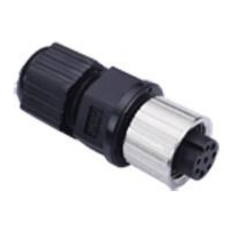
The sensor is connected via M12, 8-pin connector against the socket on the cover's body.
Pin5 GND
Pin8 pulse input
Input is designed for connection to any meter with a voltage free or transistor output interface.
Input includes internal pullup resistor 4k7. Voltage for pullup resistor is adjustable 5÷16V (default 5V)
Coupling is capacitive.
Electrical connection of the meter
(It is connected in the factory by default)
Evaluating unit is consists of two units:
Front panel with display unit Back panel with outputs, inputs and power

Technical and installation
manual FLOW 38 Batch (impulse) Page 8 (total 26) COMAC CAL s.r.o.
Terminal connection of the evaluation unit:
Terminal 1 – controlling of batching valve C
Terminal 2 – controlling of batching valve E
Terminal 3, 4 – puls output OUT IMP
Terminal 5, 6 – communication RS485
Terminal 7 – START button
Terminal 8 – STOP button
Terminal 9,10 – none
Terminal 11,12 – auxiliary voltage
These terminals are in the batching device already connected to the control supply plate.
Terminal connection and jumpers is always described on the cover sheet of power supply and back cover.
Impuls output
The output of volumetric impulses is implemented by an NPN transistor. Limit parameters of this
optocoupler are 80V/50mA/100mW max.
The volumetric impulse output is used for remote transmission of volumetric impulses. The conversion
constant is arbitrarily variable using buttons or user software. The adjustment must be carried in such a
manner that fout<400Hz.
The impulse output may be active or passive.
In active mode, the meter takes advantage of internal galvanically isolated 16V power supply. The
voltage at the output is in the state of 16V pulse, the recommended drawn current is 2.5mA. At the
moment beyond the pulse, the output is at the state of high impedance (if the input of the device does
not contain an internal pulldown resistor, it is necessary to provide it)
Wiring connection examples – passive impulse output: Terminals
Due to CR≈100% and If = 2.5 mA it is advisable to choose the collector current up to 2.5 mA.

Technical and installation
manual FLOW 38 Batch (impulse) Page 9 (total 26) COMAC CAL s.r.o.
Buttons START, STOP
Applying a signal to the GND terminal 7 or 8 you can start or stop the batch. These terminals are in
batching devices already connected to the control buttons.
Controlling of the batching valve
Terminals 1 and 2 are used to control the relay valve batching device. These terminals are in batching
devices already connected to the control board with relay outputs.
Data output
The Flow 38 Batch meter can be provided with RS485 communication interface with M-Bus protocol
according to EN 1434-3 or ModBus RTU.
Protection degree
The meters meet all the requirements for IP 65 protection degree.
Replacement of tube fuse in the meter
!!! Risk of electric shock! Uncovered components generate dangerous voltages. Before removing the
cover from the electronics area, make sure that the meter is not under voltage!!!
The instrument fuse is on the power supply PCB and it is replaced as follows:
1. Switch off power.
2. Unlock the corner screws and remove the cover instrument boxes
3. Remove the protective cover and replace the instrument fuse (use solely F50mA/250V tube fuses
for power source part and F250mA/250V for measuring part)
4. Proceed in reverse order to recover the function of the meter.
power source part measuring part

Technical and installation
manual FLOW 38 Batch (impulse) Page 10 (total 26) COMAC CAL s.r.o.
Wiring check
After completion of wiring, it is necessary to check:
-Connecting cables for damage.
-If the cables used are suitable for given cable entries.
-Cables for pull relief.
-Correct tightening of cable entries.
-Correct connection of cables to terminals.
-Whether the supply voltage corresponds with the nameplate data.
-After closing the device properly tightening the lid.
Putting into operation
Prior to connection to power supply, check the device installation accuracy in accordance with
“Installation in pipeline and “Wiring” chapters.
If you wish the meter to take measurement as precisely as possible right after powering up, it is a good
idea to fill the flow sensor with water, one or two days before its installation, so that all of its electrodes
are flooded. Just before the installation, the water is discharged and the sensor is installed into piping.
Right after installation, piping is filled with a medium so that the electrodes cannot dry off.
If the meter has no electrode for empty tube detection, do not connect the meter to power before filling
the system with the fluid to be measured and power off the meter before system discharge.
Once the meter is powered up, the green LED on the front glazed panel is lit, confirming the supply
voltage on the control PCB and stabilization of parameters of the meter takes place subsequently. The
stabilization is indicated on the meter's display. After that period of time, the meter starts measuring.
Meter status:
It is displayed continuously on the screen as one of the main menu items and in case of a non-standard
state or a failure, this is displayed by alternating indication of the status and main menu basic data and
the operator is warned by a text. The meter status is divided into 4 basic groups:
1) OK everything is all right
2) Warning the meter takes measurement but some of the parameters are out of range
3) Error critical error – the meter does not take measurement
Flow direction:
The arrow indicates the direction liquid flow inside the sensor and thus the correct orientation of the
meter's sensor for installation in piping. In case of inversely performed installation, it is possible to
toggle the direction in electronics between positive/negative and thus avoid incorrect value imaging
and reading out.
Basic parameter settings
The meter or flow meter parameters are set by the manufacturer in accordance with the purchase order.
If these values are not indicated in your purchase order, the meter will be set up using the default
parameters in accordance with the meter's range. The operator can make modifications by means of three
buttons on the meter's panel or through the RS485 interface.

Technical and installation
manual FLOW 38 Batch (impulse) Page 11 (total 26) COMAC CAL s.r.o.
Safety rules for operator
Any interventions in the inductive flow sensor and evaluation unit itself are illegal on the part of operator
and they may lead to direct scalding by medium. Perform electrical connection always after powering
off.

Technical and installation
manual FLOW 38 Batch (impulse) Page 12 (total 26) COMAC CAL s.r.o.
Flow 38 Batch operating instructions
The meter is provided with two external buttons on the side of the electronics housing and with three
internal buttons on the bottom of the measuring electronics PCB which is accessible after unscrewing
the front glazed cover.
Functions of control (lower) buttons:
Potentiometer Setting the batch size, the minimum setting value of the potentiometer
corresponds to the limit for the minimal batch and maximum value of the
potentiometer then the maximal batch (see p. 26).
Green "START" button Start the set dose from the beginning, or its restart, if the previous stop red
button.
Red “STOP” button Stop ongoing dose. In the case the batch is stopped yet, than this unfinished
dose is cancelled and the unit is ready to be restarted dose again from the
beginning of the green button.
Function of setting buttons (under display)
Before pressing Eand entering the password
short press movement in current menu up
or modification of the value at the cursor up
short press movement in current menu down or
modification of the value at the cursor down
/E long press (>3sec) entry to PARAMETERS menu
long press (>3sec) exits from PARAMETERS menu
simultaneously andresetting user rV counter
(short press approx. 0.5sec) in PARAMETERS menu while entering
values by an order back
simultaneously andin PARAMETERS menu, end of modification
of values without writing
(long press >3sec)
simultaneously andtotal restart of the meter
(long press >8sec)
Eshort press confirmation (Enter) or modification of a value (setting)
Basic display menu contains the following items:
Date and Time D/T
Current flow Q
Dose setting Vrun/stop
Volume in positive direction against the arrow on the meter's name plate + V
Volume in negative direction against the arrow on the meter's name plate - V
Total volume (summary in both directions) Σ V
Dose volume (in positive direction only) r V
Status OK

Technical and installation
manual FLOW 38 Batch (impulse) Page 13 (total 26) COMAC CAL s.r.o.
The order may vary as per meter's settings the customers may select the data to be displayed on the first
two lines (or change the order) in such a manner that corresponds to their requirements.
In case that the meter's status is found in a different than normal and correct (OK) status, measurement
failure indication alternates with the normal display indication. As a consequence, it is not necessary to
check the status all the time; in case of trouble, it is indicated on the display unit automatically.
Using both external and internal andbuttons, you can list in basic menu, reset the user volumetric
counter (by simultaneous pressing both buttons), enter PARAMETERS menu, list in it and exit from it.
Parameter settings menu contains these following items:
DATE AND TIME
OPERATION TIME COUNTER
POWER LOSS COUNTER
IMPULSE OUTPUT or FLOW SWITCH
SETTING OF THE RANGE OF DOSE
COMMUNICATION
BASIC INDOICATIONS ON DISPLAY
DISPLAY DIMMING
DISPLAY BACKLIGHT
SERIAL NUMBER
IMPULSE CONSTANT OF EXTERNAL SENSOR
EMPTY TUBE TEST
FIRMWARE VERSION
DEAD BAND – MEASUREMENT START SUPPRESSION*
ZERO CALIBRATION*
FLOW SIMULATION
LANGUAGE
COUNTER RESETTING*
NOMINAL DIAMETER (DN)
FLOW DIRECTION*
FLOW UNITS DISPLAYED [Q]
VOLUME UNITS DISPLAYED [V]*
PASSWORD CHANGE
DEFAULT SETTINGS (ORIGINAL FACTORY SETTINGS)
* If the meter is delivered for billing purposes, then these parameters marked with an asterisk cannot
be changed (in case of restoration of factory settings, the volumetric counter is not reset).
For editing items in PARAMETERS menu, the central Ebutton is used, once it is pressed down, the
operator is asked for authorization of access by password (by default, it is 0000). Consequently, it is
possible to use the andbuttons to change the value upwards or downwards and confirm the
modification by the central Ebutton. In case that the parameter to be changed is not a numerical one,
the entire parameter is changed by means of a "scroll bar". The password is required only at the first

Technical and installation
manual FLOW 38 Batch (impulse) Page 14 (total 26) COMAC CAL s.r.o.
entry and it will become invalid after returning to basic display or within two and a half minutes of
inactivity when the meter returns again to its basic display automatically
Examples of representation in normal status according to user settings:
Note: The order of representation of menu items can be modified by user according to the customer's
needs.
Procedure to set individual menu items:
Within framework of setting, it is necessary to unscrew the front cover with glass window to get access
to internal buttons. After initial entry to Parameter’s menu (long press of ) and an attempt to edit an
item (by E button), the operator is asked for entering an authorization access code (by default 0000).
This is entered successively for each of four digits separately from left to right using the or buttons
whereas the transfer of cursor to another digit, including the final confirmation of the entire code is
implemented by the Ebutton. By applying a double press (simultaneously andshort press
approx. 0.5sec) you can return by one position and correct it. In case of entering an invalid password,
modification of parameters is not enabled and the password entry must be repeated.
Note: The password will become invalid after returning to basic display or within two and a half minutes
of inactivity when the meter returns again to its basic display automatically.
Entering numerical values for individual menu items takes place in a similar manner.
If it is not a freely adjustable numerical item but a list of possible values, the selection is implemented
by successive scrolling using the or buttons and once the desired value is displayed, you simply
confirm the selection by pressing the Ebutton.
After successful entry, the confirmation of the request for modification is required by the or
buttons, followed by\ selecting YES/NO and confirming by the Ebutton. By doing this, the modification
is saved in the internal memory of the meter.

Technical and installation
manual FLOW 38 Batch (impulse) Page 15 (total 26) COMAC CAL s.r.o.
Date and time
This menu item is in DD/MM/RRRR HH/MM formats
Use the andbuttons to set the menu item on the display and press the Eto edit. Implement settings
in a standard way, using the setting buttons and confirm by pressing the Ebutton.
It is necessary again to confirm the change.
Operation time counter
The counter registers the operation time of the meter (switching on). The first line indicates the date
when the last counter reset was performed and the second line indicates the length of operation in days,
hours and minutes.
This counter can be reset by pressing the Ebutton when necessary.
Power loss counter
The counter registers the time of loss of power time for the meter. The first line indicates the date when
the last reset of power loss counter was performed and the second line indicates the length of time when
the meter was out of operation in days, hours and minutes. The counter can be reset again by pressing
the Ebutton.

Technical and installation
manual FLOW 38 Batch (impulse) Page 16 (total 26) COMAC CAL s.r.o.
Impulse output / flow switch
This output can be configured as the impulse output or the Flow Switch contact.
Impulse output
For complete setting the parameters of impulse output, it is possible to change the logics (polarity) of
the electrical signal (positive/negative), to set the impulse output to which the volumetric counter will
respond (volume run in positive direction, in opposite direction and in both directions) as well as your
own impulse constant, including its indication (imp/L or L/imp).
The impulse width cannot be set freely using an arbitrary value but it is necessary to select a suitable
impulse width from the predefined width menu (by scrolling the predefined values using the or )
buttons.
Flow switch
For complete setting the parameters of status output, it is possible to change the logics (polarity) of the
electrical signal (positive/negative) and then set to which volume the output will respond (flow in
positive direction, in opposite direction and in both directions) as well as your own switching point value.
The status contact makes it possible to set the amount of hysteresis between Qon and Qoff states.

Technical and installation
manual FLOW 38 Batch (impulse) Page 17 (total 26) COMAC CAL s.r.o.
Setting of the range of dose
For Setting dose range uses two parameters, which set the maximum and minimum of dose between the
rotary element. Selecting of the maximum value automatically affects the resolution in which it is
possible to adjust the dose so that was the setting value by rotary buttons stable - usually can figure set
to 3 significant figures (999 position of rotary switch). It means for settled max. dose 1000 litres will be
one step 10 litres changing by the rotary switch etc.
Setting then proceeds in a conventional way by changing the dose in m3 for the minimum, and
consequently the maximum limit.
Communication
If the meter is ordered with communication, it is possible to set all of its parameters. For selection of an
address, any number 0 – 255 can be set and the velocity should be selected according to custom practice.
If you wish to change the type of communication, press the E button. Then press (simultaneously
andapprox. >0.5sec). Select the desired communication type by or and confirm the selection
by the E button.
Once the MBus/MODBUS type of protocol is to be changed, the recommended velocity for these
communication types is completed automatically.
If communication was not ordered.

Technical and installation
manual FLOW 38 Batch (impulse) Page 18 (total 26) COMAC CAL s.r.o.
Idle state basic indications on display
Basic indications in idle state can be influenced and modified in such a manner that the data needed by
the user can be found on the first two lines on the display. Whereas the order of the other items is retained.
If you want to change a setting, press the Eand orbuttons and select the data on the line which is
then confirmed by the Ebutton. The customer can select from these indications, namely both on the first
and the second lines:
-Date and Time
-Dose volume user defined volume rV
-Total volume ∑V sum of volumes in both directions
-Volume (-) direction reverse flow volume -V
-Volume (+) direction volume in positive flow direction +V
-Dose setting
-Flow current flow Q

Technical and installation
manual FLOW 38 Batch (impulse) Page 19 (total 26) COMAC CAL s.r.o.
Display dimming
The period of averaging flow values within the range is set here. Maximum value is 29sec. Averaging
is then used for the other outputs as well.
Display backlight
Here, you can set the period during which the display backlight is turned off after the last activation of
a button. Use the andbuttons to select the desired settings from menu (permanent, 40sec, 20sec,
10sec, switched off).
Serial number
The serial number is registered in the factory and cannot be changed by user.
Impulse constant of external sensor
Allows you to set the pulse constant of the external flow sensor.
Empty tube test
Activates and deactivates monitoring of measuring tube filling. If the meter was ordered without the
testing electrode, the flooding test cannot be activated. Two levels of the empty tube test activation are
available for standard conductivity ON(1) and for increased conductivity ON(2).

Technical and installation
manual FLOW 38 Batch (impulse) Page 20 (total 26) COMAC CAL s.r.o.
Firmware version
The firmware version is registered in the factory and cannot be changed by user.
Dead band – measurement start suppression
If you want to change the flow value for the start of measurement, press the Ebutton.
Zero calibration
The date under "Zero calibration" heading indicates the date when zero flow calibration was performed.
If you want to recalibrate the zero flow, press the Ebutton. The flow meter evaluates the measured data
automatically and if YES is set, upon confirmation of the selection by the E button, a new value for zero
flow will be set and the date of the last recalibration is updated (when NO is selected, the value for
recalibration is not registered and everything remains in original setting.
Note: Before recalibration is performed, do not forget to close the valves first and secure a real zero
flow (stationary medium) in the system.
Table of contents
Other COMAC CAL Measuring Instrument manuals

COMAC CAL
COMAC CAL FLOW 33 Use and care manual

COMAC CAL
COMAC CAL FLOW 45 Use and care manual

COMAC CAL
COMAC CAL CALOR 38 Use and care manual

COMAC CAL
COMAC CAL FLOW 38 Use and care manual

COMAC CAL
COMAC CAL FLOW 38 User manual

COMAC CAL
COMAC CAL FLOW 33Exia MGD Use and care manual

COMAC CAL
COMAC CAL FLOW 38 BATCH Use and care manual

COMAC CAL
COMAC CAL FPW Use and care manual

COMAC CAL
COMAC CAL CALOR 40 User manual

COMAC CAL
COMAC CAL FLOW 32 Use and care manual