FLOW 33Exia Manual Page 3 (total 33) COMAC CAL s.r.o.
Description of device
The FLOW 33Exia meter is based on measurement principle by a well-known Faraday's
electromagnetic induction law according to which an electric voltage is induced during the flow of a
conductive liquid through the flow meter magnetic field. This is picked up by two electrodes in direct
contact with the measured medium and evaluated in the electronic unit.
The FLOW 33Exia type of induction meters are suitable exclusively for measurement of volumetric
flow of electrically conductive liquid substances with a minimum conductivity of 20 S/cm (at a
lower conductivity, upon agreement with the manufacturer).
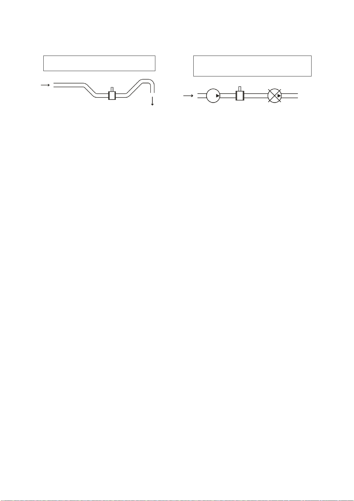
Meters are designed for flow measurement where the velocity of liquid is in the range of 0.01 ÷ 12
m/s. The best measurement accuracy can be obtained in the range of 1 ÷ 10 m/s.
Flow 33Ex are firmly integrated in the pipe system of underground mine, chemical or other
application where exist the risk of explosive gases and dusts. They are formed by corundum
measuring pipe in diameter DN 15, DN 25, DN 32, DN 40, DN 50, DN 65 and DN 80 or stainless
steel measuring pipe with rubber or PTFE lining in DN15, DN 20, DN 25, DN 32, DN 40, DN 50,
DN 65, DN 80, DN 100, DN 125, DN 150 and DN 200. Pipes are inside stainless steel housing fitted
with different types of process connection. On the housing is fixed stainless steel cover for evaluation
unit with electronics of sensor, which is fitted with stainless steel top cover equipped with connector
for wiring of flowmeter to next devices.
The entire inner space of flowmeter is filled with sealing compound for protection against humidity
and increase protection against ignition of surrounding atmosphere in the hazardous area. Therefore,
after filling of the whole system is flowmeter disassembled and any changes in construction are not
possible.
Scope of delivery
Accessories vary according to the variant of flow sensor and above standard optional features.
Threaded design
Electronic evaluation unit in a compact design (the electronic unit is integral part of the flow sensor),
flow sensor, connecting grounding cable, installation manual.
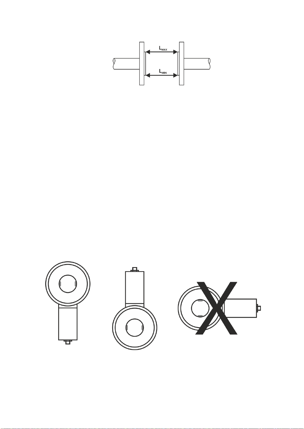
Sandwich design
Electronic evaluation unit in a compact design (the electronic unit is integral part of the flow sensor),
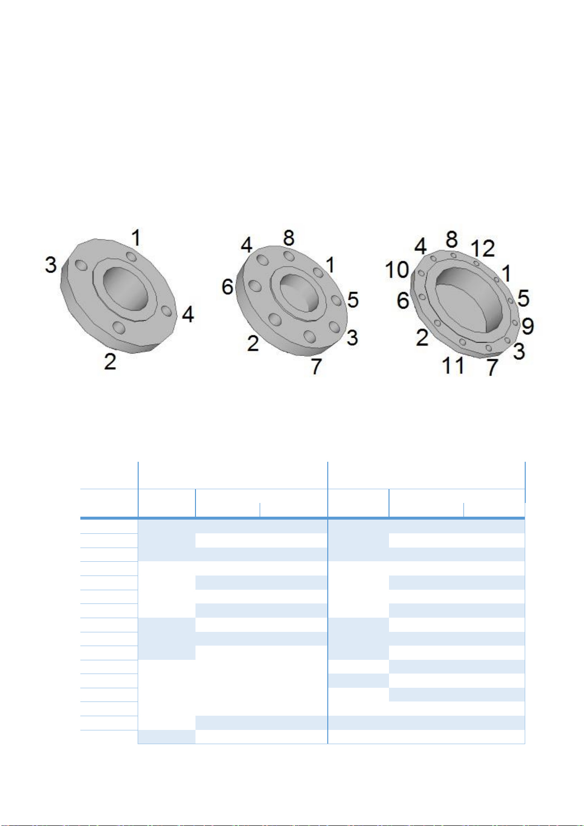
flow sensor, bolts for installation of the sensor between flanges (quantity as per tightening torque
table, see below) with nuts and washers, connecting grounding cable, installation manual.
Flanged design
Electronic evaluation unit in a compact design (the electronic unit is integral part of the flow sensor),
flow sensor, connecting grounding cable, installation manual.
Food industry design
Electronic evaluation unit in a compact design (the electronic unit is integral part of the flow sensor),
flow sensor, adapter piping connection according to DIN 11851, installation manual.