manuals.online logo
Brands
  1. Home
  2. •
  3. Brands
  4. •
  5. COMBA
  6. •
  7. Antenna
  8. •
  9. COMBA PM-AS-ODP-033R11MJ53-SL User manual

COMBA PM-AS-ODP-033R11MJ53-SL User manual

Other COMBA Antenna manuals

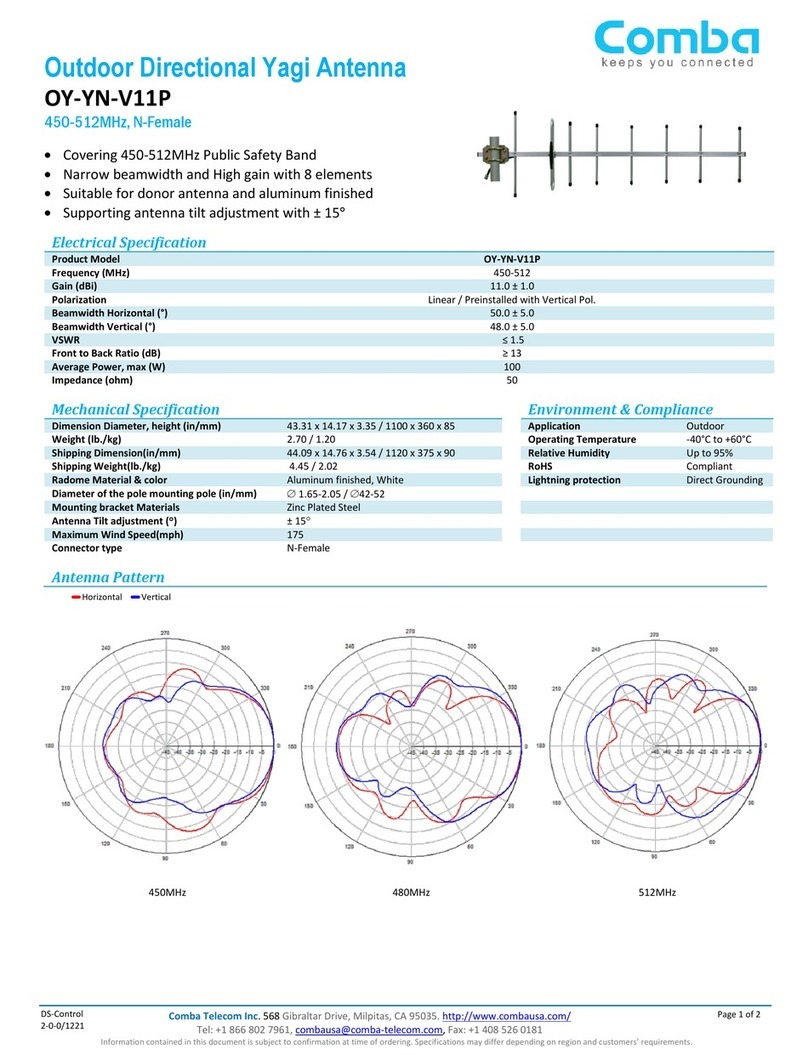
COMBA OY-YN-V11P User manual

COMBA

COMBA OY-YN-V11P User manual

COMBA OY-YN-V11P User manual

COMBA

COMBA OY-YN-V11P User manual

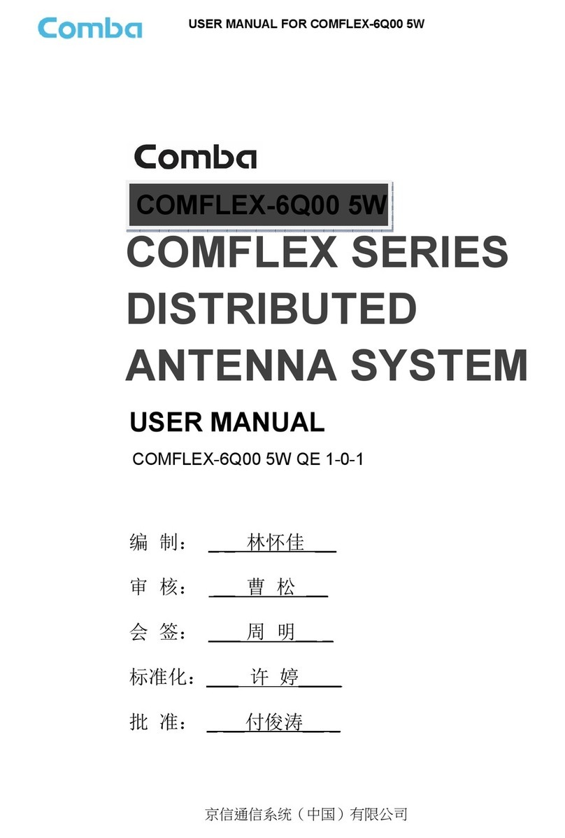
COMBA COMFLEX Series User manual

COMBA

COMBA COMFLEX Series User manual

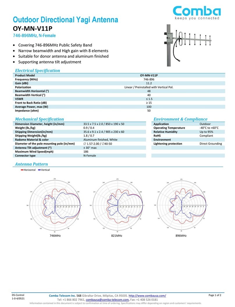
COMBA OY-MN-V11P User manual

COMBA

COMBA OY-MN-V11P User manual

Popular Antenna manuals by other brands

DAVIS Windex AV 3160 installation instructions

DAVIS

DAVIS Windex AV 3160 installation instructions

Belden Hirschmann BAT-ANT-N-14G-IP23 Mounting instruction

Belden

Belden Hirschmann BAT-ANT-N-14G-IP23 Mounting instruction

Vtronix YHK Fitting instructions

Vtronix

Vtronix YHK Fitting instructions

KVH Industries TracVision 6 Technical manual

KVH Industries

KVH Industries TracVision 6 Technical manual

Leica Geosystems GS10 user manual

Leica Geosystems

Leica Geosystems GS10 user manual

Sirio Antenne Gain-Master manual

Sirio Antenne

Sirio Antenne Gain-Master manual

Sony VCA-41 Installation/connections

Sony

Sony VCA-41 Installation/connections

ZCG Y100 Series installation guide

ZCG

ZCG Y100 Series installation guide

Advantech Wireless INTREPID120 Assembly instructions

Advantech Wireless

Advantech Wireless INTREPID120 Assembly instructions

Cerio ANT-10AO installation guide

Cerio

Cerio ANT-10AO installation guide

Alfa Network APA-L01 Specifications

Alfa Network

Alfa Network APA-L01 Specifications

Naval PR-422CA Operation manual

Naval

Naval PR-422CA Operation manual

Feig Electronic ID ISC.ANTH200/200 Series manual

Feig Electronic

Feig Electronic ID ISC.ANTH200/200 Series manual

TERK Technologies TV44 owner's manual

TERK Technologies

TERK Technologies TV44 owner's manual

TERK Technologies SIR3 owner's manual

TERK Technologies

TERK Technologies SIR3 owner's manual

Directive Systems & Engineering DSE2324LYRMK quick start guide

Directive Systems & Engineering

Directive Systems & Engineering DSE2324LYRMK quick start guide

HP J8999A instructions

HP

HP J8999A instructions

MobilSat MSP-S Mounting instructions

MobilSat

MobilSat MSP-S Mounting instructions

manuals.online logo
manuals.online logoBrands
  • About & Mission
  • Contact us
  • Privacy Policy
  • Terms and Conditions

Copyright 2025 Manuals.Online. All Rights Reserved.

© 2015 Comba Telecom. All rights reserved
Information contained in this document is subject to confirmation at time of ordering.
Specifications may differ depending on regi
on and customers’ requirements.
DS-Control: 1-0-0 / 0118
Outdoor
Narrow Bea
PM-AS-ODP-033R11MJ53
-
X Pol, 33°
698-960/1710-2700MHz
11.5/11.5dBi
Electrical Specifications
Parameters/Specifications
Frequency Range
Polarization
Gain
H-Beamwidth
V-Beamwidth
Isolation
Front to back ratio
Cross Polar Ratio
VSWR
PIM3 at 2x43 dBm
Impedance
Power Rating
Mechanical Specifications
Parameters
Product Dimension, HxWxD
Product Weight (Antenna&Mounting
Kits
Packing Dimension, HxWxD
Packing Weight
(Mounting Kits included)
Install Position Adjustment
Pole Mounting Diameter
Radome Material
Connector Type
Environmental Specifications
Parameters
Operational Temperature
Operational Humidity @30℃
Information contained in this document is subject to confirmation at time of ordering.
on and customers’ requirements.
Narrow Bea
m Directional Antenna
-
SL
Unit
Frequency Range (MHz)
MHz 698-960 1710-
2200
deg ±45
dBi 11.5±1.5 11.5±1
.5
deg 33±8 33±8
deg 65±10 60±10
dB ≥24
dB ≥20
dB
≥15
<1.9
dBc <-153
Ω 50
W 100
Unit
Specification
mm 655x385x
122.5
Kits
) Kg 9.8
mm 905x460
x2
(Mounting Kits included)
Kg 12.9
Deg ±10
mm Φ50-
80
FRP
2 x 7/16 DIN-
Female
Unit
Specifications
℃
-40~+
65
% < 95
Page 1
Frequency Range (MHz)
2200
2200-2700
.5
11.5±1.5
30±8
63±12
Specification
s
122.5
x2
80
80
Female
Specifications
65
© 2015 Comba Telecom. All rights reserved
Information contained in this document is subject to confirmation at time of ordering.
Specifications may differ depending on regi
on and customers’ requirements.
DS-Control: 1-0-0 / 0118
INSTALLATION INSTRUCTION
Step 1:Assemble the bracket
Step 2:Install the bracket
As shown, put the mounting
bracket onto the
mounting pole and tighten the two M10.
Mounting pole Φ50-Φ
80mm(not supply)
Step 3:Install the Antenna
Remove the four screws from the antenna back
panel, and install the antenna onto the bracket
through the four screws.
Information contained in this document is subject to confirmation at time of ordering.
on and customers’ requirements.
INSTALLATION INSTRUCTION
bracket onto the
mounting pole and tighten the two M10.
80mm(not supply)
Remove the four screws from the antenna back
panel, and install the antenna onto the bracket
Step 4:
Adjust the mechanical downtilt angle
The antenna can be turned horizontally and vertically,
both
adjustment range is ±45°,then tighten all the
screws. (please use the inclinometer for the
precise angle)
*
Only qualified personnel are allowed to install the
antenna.
Nuts
Torque
M8
M10
Page 2
Adjust the mechanical downtilt angle
The antenna can be turned horizontally and vertically,
adjustment range is ±45°,then tighten all the
screws. (please use the inclinometer for the
Only qualified personnel are allowed to install the
Torque
20 Nm
44 Nm