Combat HVAC Limited Combat CTCU 11 Installation and operating instructions

WARNING
FOR YOUR SAFETY
If you smell gas:
1. Open windows.
2. DO NOT try to light any appliance.
3. DO NOT use electrical switches.
4. DO NOT use any telephone in
your building.
5. Extinguish any open flame.
6. Leave the building.
7. Immediately call your local gas
supplier after leaving the building.
Follow the gas supplier’s
instructions.
8. If you cannot reach your gas
supplier, call the Fire Department.
Fire Hazard
Keep all flammable objects, liquids and
vapours the minimum required
clearances to combustibles away from
heater.
Some objects will catch fire or explode
when placed close to heater.
Failure to follow these instructions can
result in death, injury or property
damage.
WARNING
Installation must be done by a registered installer/
contractor qualified in the installation and service
of gas-fired heating equipment or your gas supplier
Improper installation, adjustment, alteration, service
or maintenance can result in death, injury or property
damage Read the installation, operation and service
manual thoroughly before installing or servicing
this equipment
Installer
Please take the time to read and understand
these instructions prior to any installation.
Installer must give a copy of this manual to the owner.
Owner
Keep this manual in a safe place in order to provide
your service technician with necessary information.
© 2016Combat HVAC Limited
Combat HVAC Limited
Unit 20 Red Mill Trading Estate
Rigby Street, Wednesbury,
West Midlands, WS10 0NP
Telephone: +44(0)121 506 7700
Fax: +44 (0)121 506 7701
Service Telephone: +44 (0)121 5067709
Service Fax: +44 (0)121 506 7702
E-mail: uksales@combat.co.uk
E-mail: export@combat.co.uk
www.combat.co.uk
Combat®
Installation, Commissioning,
Operation & Service Manual
Models
CTCU 11
CTCU 15
CTCU 22
CTCU 27
CTCU 32
P/N 111100UK CTCU01116 Rev1
Compact Tubular Unit Heaters

Combat HVAC Limited
Registered in England at the above address
Company Registration Number: 2955148
Combat HVAC Limited
Unit 20, Red Mill Trading Estate
Rigby Street, Wednesbury,
West Midlands,WS10 0NP, UK
Telephone: +44 (0) 121 506 7700
Fax: +44 (0) 121 506 7701
Service Telephone: +44 (0) 121 506 7709
Service Fax: +44 (0) 121 506 7702
Sales Fax: +44 (0) 121 506 7703
Website: www.combat.co.uk
Email: uksales@combat.co.uk
DECLARATION OF CONFORMANCE
CERTIFICATION BODY: KIWA GASTEC NOTIFICATION BODY N
o
:0558
GAS FIRED WARM AIR PRODUCT RANGE
CTCU
CTU
MGB
DECLARATION:
Combat HVAC Limited hereby declare we are authorised to manufacture
the above range of gas fired warm air heaters which are manufactured
and in accordance with the CE and Essential Requirements of the Gas
Appliance Directive 2009/142/EC (ex-90/396/EEC).
Yours Faithfully
Kind Regards

© 2016Combat HVAC Limited
All rights reserved. Nopartof this work covered bythe copyrights herein maybereproduced
or copied in any form or by any means - graphic, electronic, or mechanical, including
photocopying, recording, taping or information storage and retrieval systems - without
the written permission of Combat HVAC Limited.
Printed in U.K.
TABLE OF CONTENTS
SECTION 1: Heater Safety...................................................... 2
1.1 Manpower Requirements ............................................. 2
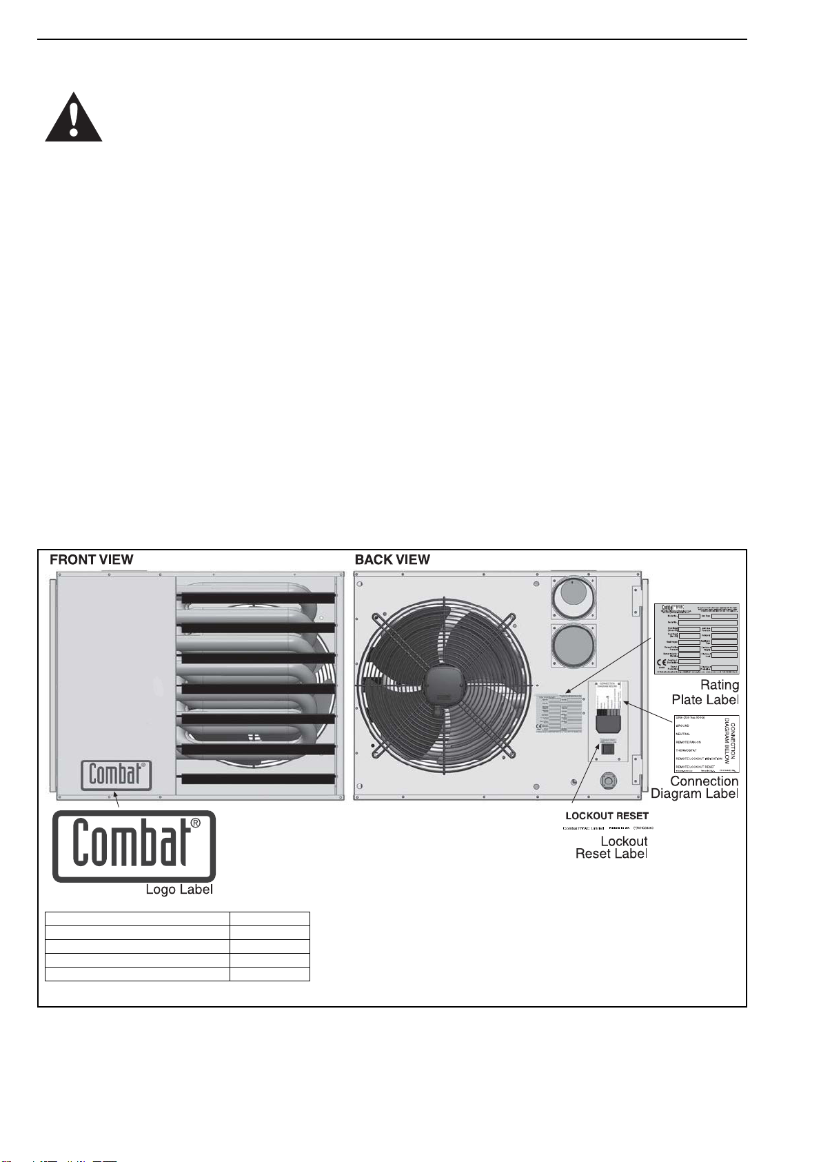
1.2 Safety Labels and Their Placement .............................2
SECTION 2: Installer Responsibility ..................................... 4
2.1 Clearances to Combustibles ........................................ 4
2.2 Corrosive Chemicals.................................................... 4
2.3 National Standards and Applicable Codes .................. 4
SECTION 3: Clearances to Combustibles............................. 5
3.1 Required Clearances to Combustibles......................... 5
SECTION 4: Critcal Considerations ...................................... 7
4.1 Ventilation .................................................................... 7
4.2 Gas Supply .................................................................. 7
4.3 Electrical Supply .......................................................... 7
4.4 Flue.............................................................................. 7
SECTION 5: Specifications .................................................... 8
5.1 CTCUA (All Models) ....................................................8
5.2 General Technical Data Table (All Models) ..................9
5.3 Technical Data Table (All Models)................................ 9
SECTION 6: Heater Installation............................................ 10
6.1 General...................................................................... 10
6.2 Basic Information....................................................... 10
6.3 Location and Suspension .......................................... 10
6.4 Handling .................................................................... 10
6.5 Suspension and Shelf Mounting ................................ 10
6.6 Wall Mounting ............................................................ 10
SECTION 7: Flue Installation ............................................... 13
7. 1 F l ue Installation .......................................................... 13
7.2 Changing Flue and Air Intake Orientation .................. 13
7.3 Type C12, C32 & C62 Appliance..................................... 13
7.4 Type B22 Appliance ..................................................... 13
SECTION 8: Air Supply......................................................... 16
8.1 Room Sealed Installation........................................... 16
8.2 Open Flued Installation.............................................. 16
8.3 Building Ventilation .................................................... 16
SECTION 9: Gas Pipe Work.................................................. 17
9.1 Connections............................................................... 17
SECTION 10: Wiringand Electrical Information................. 19
10.1 Electrical Supply ...................................................... 19
10.2 Remote Controls ...................................................... 19
10.3 CTCUA Wiring Diagram (All Models) ....................... 20
SECTION 11: Commissioning.............................................. 21
11.1 Pre-Commission Checks .......................................... 21
11.2 Gas Supply ............................................................... 21
11.3 Mechanical Checks................................................... 21
11.4 Begin Commissioning............................................... 22
11.5 Co m bustion Testing .................................................. 23
11.6 Turning Off the Heater .............................................. 23
11.7 External Controls ...................................................... 23
11.8 Complete the Commissioning................................... 24
11.9 Instruction to the User .............................................. 24
SECTION 12: User Instructions ........................................... 25
12.1 User Instructions...................................................... 25
12.2 Heater Operation ..................................................... 25
12.3 Common User Controls ...........................................25
12.4 Lighting Instructions................................................. 26
12.5 Simple Fault Finding ................................................ 26
SECTION 13: Servicing.........................................................27
13.1 Servicing Instructions...............................................27
13.2 Burner Maintenance.................................................27
13.3 Fan/Motor Assembly Maintenance ...........................27
13.4 Heat Exchanger Maintenance..................................27
13.5 Gas Control Valve Maintenance ...............................28
13.6 Flue Fan ...................................................................28
13.7 Maintenance Checklist .............................................28
SECTION 14: Conversion Between Gases ..........................30
14.1 General ....................................................................30
14.2 Burner Conversion ...................................................30
14.3 Gas Valves ...............................................................30
SECTION 15: Troubleshooting.............................................31
15.1 General ....................................................................32
15.2 Troubleshooting For Automatic Ignition Burner
Systems....................................................................33
15.3 Troubleshooting for Flame Supervision System .......34
15.4 Troubleshooting for Solenoid Valves ........................34
15.5 Troubleshooting for Main Fan ...................................35
SECTION 16: Removal and Replacement Parts..................36
16.1 Gas Valve .................................................................36
16.2 Ignition Electrode and Flame Probe .........................38
16.3 Flue Fan Vertical Installation (All Models) ................39
16.4 Pressure Switch........................................................40
16.5 Ignition Control .........................................................41
16.6 CTCUA Axial Fan/Guard/Motor Assembly ...............41
16.7 Fan and Limit Thermostats ......................................41


TABLE OF FIGURES
Figure 1: Front and Back Panel Label Placement.....................2
Figure 2: Side Panel Label Placement...................................... 3
Figure 3: Installation Clearances and Clearances to
Combustibles............................................................. 6
Figure 4: Suspension Methods ............................................... 11
Figure 5: Shelf Mounting and Hanging Suspension................ 12
Figure 6: Vertical Louvres (Optional) ...................................... 12
Figure 7: Flue and Roof Detail ................................................ 14
Figure 8: Vertical and Horizontal Flue Termination -
Type B22 Appliance .................................................. 14
Figure 9: Vertical and Horizontal Flue Termination -
Type C12 C32 & C62 Appliances................................. 15
Figure 10: Gas Connection with Stainless Steel Flex
Connector .............................................................. 18
Figure 11: Automatic Burner Control Box Sequence............... 22
Figure 12: Gas Valve for Heater (All Models) .......................... 23
Figure 13: Heater Operating Sequence .................................. 25


1 of 41
Product Approval
COMBAT appliances have been tested and CE Certified as complying with the essential requirements of the Gas
Appliance Directive, the Low Voltage Directive, the Electromagnetic Compatibility Directive and the Machinery Directive
for use on natural gas and LPG when installed, commissioned and maintained in accordance with these instructions.
These instructions refer to appliances designated to operate in the European Union.
Appliances designed for other countries (Non European Union) are available upon request.
This appliance must be installed in accordance with the local and national codes in force and used only in a sufficiently
ventilated space, as specified in these instructions.
Before installation, check that the local gas distribution systems, nature of gas and pressure, and adjustment of the
appliance are compatible.

COMBAT®CTCU UNIT HEATERS INSTALLATION OPERATION AND SERVICE MANUAL
2 of 41
SECTION 1: HEATER SAFETY
Yo ur Safety is Important to Us!
This symbol is used throughout the
manual to notify youof possible fire,
electrical or burn hazards. Please pay
special attention when reading and
following the warnings in these sections.
Installation, service and annual inspection of heater
must be done by a registered installer/contractor
qualified in the installation and service of gas-fired
heating equipment.
Read this manual carefully before installation,
operation, or service of this equipment.
This heater is designed for heating non-residential
indoor spaces. Do not install in residential spaces.
These instructions, the layout drawing, local codes
and ordinances, and applicable standards that apply
to gas piping, electrical wiring, venting, etc. must be
thoroughly understood before proceeding with the
installation.
Protective gear is to be worn during installation,
operation and service. Thin sheet metal parts have
sharp edges. To prevent injury, the use of work
gloves is recommended. The use of gloves will also
prevent the transfer of body oils from the hands.
Before installation, check that the local distribution
conditions, nature of gas and pressure, and
adjustment of the appliance are compatible.
The heater must be applied and operated under the
general concepts of reasonable use and installed
using best building practices.
This appliance is not intended for use bypersons
(including children) with reduced physical, sensory
or mental capabilities, or lackof experience and
knowledge, unless they havebeen given
supervision or instruction concerning use of the
appliance by a person responsible for their safety.
Children should be supervised to ensure that they
do noplay with the appliance.
For additional copies of the Installation, Operation
and Service Manual, please contact Combat HVAC
Limited.
1.1 Manpower Requirements
To prevent personal injury and damage to the
heater, two persons will be required for installation.
1.2 Safety Labels and Their Placement
Product safety signs or labels should be replaced by
the product user when they are no longer legible.
Contact Combat HVAC Limited for obtaining
replacement signs or labels. See Page 2, Figure 1
through Page 3, Figure 2.
Figure 1: Front and Back Panel Label Placement
Description Part Number
Logo Label 91040030
Lockout Reset Label 91038303
Rating Plate Label 91040001
Connection Diagram Label 91040022

SECTION 1: HEATER SAFETY
3 of 41
Figure 2: Side Panel Label Placement
Description Part Number
Lighting Label 91040002
Address Label 91040006
Wiring Diagram Label 91040020

COMBAT®CTCU UNIT HEATERS INSTALLATION OPERATION AND SERVICE MANUAL
SECTION 2: INSTALLER RESPONSIBILITY
•Toinstall the heater, as well as the gas and
electrical supplies, in accordance with applicable
specifications and codes. Combat HVAC
Limited recommends the installer contact a local
building inspector, Fire Officer or insurance
company for guidance.
•Touse the information given in the manual
together with the local and national codes to
perform the installation.
•Toinstall the heater in accordance with the
clearances to combustibles of this heater.
•Tofurnish all needed materials not furnished as
standard equipment.
•Toplan location of supports, flues and air
intakes.
•Toprovide access to burners for servicing.
•Toprovide the owner with a copy of this
installation, commissioning, operation and
service manual.
•Tonever use heater as support for ladder or
other access equipment and never hang or
suspend anything from heater.
•Toensure that there is sufficient ventilation in the
area to comply with the requirements of all
relevant local and national codes.
•Tosafely and adequately install heater using
materials with a minimal working load of 33 kg.
•Toensure the heater is placed in an approved
application.
2.1 Clearances to Combustibles
A laminated wall tag is available for the heater as a
permanent reminder of the safety instructions and
the importance of the required clearances to
combustibles. Affix the tag by peeling off the backing
of the adhesive strips on the rear surface and
position the tag on a wall near the heater (e.g.
thermostat or Combat®Controller).
A copy of the wall tag (P/N 91040029) is illustrated
on the back cover. Knowyour model number and
installed configuration. Model number and installed
configuration are found on the burner and in the
Installation, Operation and Service Manual. Write
the largest clearance dimensions with permanent
ink according to your model number and
configuration in the open spaces on the tag.
4 of 41
2.2 Corrosive Chemicals
Combat HVAC Limited cannot be responsible for
ensuring that all appropriate safety measures are
undertaken prior to installation; this is entirely the
responsibility of the installer. It is essential that the
contractor, the sub-contractor, or the owner
identifies the presence of combustible materials,
corrosivechemicals or halogenated hydrocarbons*
anywhere in the premises.
* Halogenated Hydrocarbons are a family of chemical
compounds characterized by the presence of halogen
elements (fluorine, chlorine, bromine, etc.). These com-
pounds are frequently used in refrigerants, cleaning
agents, solvents, etc. If these compounds enter the air
supply of the burner,the lifespan of the heater compo-
nents will be greatly reduced. Warranty will be invalid if
the heater is exposed to halogenated hydrocarbons.
2.3 National Standards and Applicable Codes
All appliances must be installed in accordance with
the latest revision of applicable standards and local
and national codes. This refers also tothe electric,
gas and venting installation. Note: Additional
standards for installations in public garages, aircraft
hangars, etc. may be applicable.
CAUTION
Product Damage Hazard
Do not use heater in area containing
corrosive chemicals.
Refer to appropriate Material Safety Data
Sheets (MSDS).
Failure to follow these instructions can result
in product damage.

SECTION 3: CLEARANCES TO COMBUSTIBLES
5 of 41
SECTION 3: CLEARANCES TO COMBUSTIBLES
3.1 Required Clearances to Combustibles
Clearances are the required distances that
combustible objects must be away from the heater
to prevent fire hazards. Caution should be used
when running the system near combustibles.
Combustibles are materials, which may catch on fire
and include common items such as wood, paper,
rubber, fabric, etc. Maintain clearances to
combustibles at all times for safety.
Clearances around the heater and flue must be as
indicated on Page 6, Figure 3, to ensure access for
servicing, and correct operation. If clearances to
combustibles are not indicated, then installation
clearances apply.
Check the clearances on each burner for the model
heater being installed to make sure the product is
suitable for your application and the clearances are
maintained. Read and followthe safety guidelines
below:
• Keep petrol or other combustible materials
including flammable objects, liquids, dust or
vapours away from this heater or any other appli-
ance.
• Do not spray aerosols in the vicinity of this appli-
ance.
• The stated clearances to combustibles rep-
resents a surface temperature of 50° C (90° F)
above room temperature. Building materials with
a lowheat tolerance (such as plastics, vinyl sid-
ing, canvas, tri-ply, etc) may be subject to degra-
dation at lower temperatures. It is the installer’s
responsibility to assure that adjacent materials
are protected from degradation.
• Maintain clearances from heat sensitive equip-
ment and workstations.
• Maintain clearances from vehicles parked below
the heater.
• Maintain clearances from swinging and over-
head doors, overhead cranes, vehicle lifts, parti-
tions, storage racks, hoists, building
construction, etc.
• In locations used for the storage of combustible
materials, signs must be posted to specify the
maximum permissible stacking height to main-
tain required clearances from the heater to the
combustibles. Signs must be posted adjacent to
the heater thermostat. In the absence of a ther-
mostat, signs must be posted in a conspicuous
location.
•Consult local Building Inspector, Fire Insurance
Carrier or other authorities for approval of pro-
posed installation when there is a possibility of
exposure to combustible airborne materials or
vapours.
• Hang heater in accordance to the minimum
suspension requirements on Page 10, Section 6
and Page 11, Figure 4 through Page 12, Figure
5.
• Affix the tag on a wall near the heater.
WARNING
Fire Hazard
Keep all flammable objects, liquids and
vapours the minimum required clearances to
combustibles away from heater.
Some objects will catch fire or explode when
placed close to heater.
Failure to follow these instructions can result
in death, injury or property damage.

COMBAT®CTCU UNIT HEATERS INSTALLATION OPERATION AND SERVICE MANUAL
6 of 41
Figure 3: Installation Clearances and Clearances to Combustibles
If installed at lowlevels where individuals can come in contact with hot heat exchanger components,
adequate guarding must be provided.
All distances are minimum clearance requirements for service access, air flowand safety.
The heater must always be installed at least 1.8 m above the floor.
The flue pipe must have clearance from combustibles by 50 mm.
* Heaters may be mounted at a higher level if destratification
fans are installed.
**800 mm is necessary to service
heater.

SECTION 4: CRITCAL CONSIDERATIONS
7 of 41
SECTION 4: CRITCAL CONSIDERATIONS
4.1 Ventilation
It is important to ensure that there is adequate air
circulation around the heater to supply air for
combustion, ventilation and distribution in
accordance with local and national codes.
4.2 Gas Supply
It is important that the gas supply pipe is sized
correctly to provide the inlet pressure as stated on
the heater data plate. The gas supply pipe and
electrical connections must not support any of the
heater's weight.
4.3 Electrical Supply
A permanent 230 V 50 Hz 1Ø electrical supply is
required at the main electrical terminals. The heater
also requires suitable energy controls in accordance
with Page 19, Section 10.
4.4 Flue
Choose heater siting to allowfor the proper location
of the flue. Each heater must be fitted with an
individual and correctly sized sealed flue system
(See Page 13, Section 7).
No other appliance may be connected to the flue.
For room sealed installation, the air intake must be
the same size sealed system and the flue/air intake
must terminate at an approved concentric wall or
roof terminal.
WARNING
Carbon Monoxide Hazard
Heaters may be installed vented or unvented.
Vented heaters must be vented outdoors.
Unvented heaters must be installed in
buildings with ventilation rates as per
section 7.
Failure to follow these instructions can result
in death or injury.
DANGER
Electrical Shock Hazard
Disconnect electric before service.
Heater must be properly grounded.
Failure to follow these instructions can result
in death or electrical shock.

COMBAT®CTCU UNIT HEATERS INSTALLATION OPERATION AND SERVICE MANUAL
8 of 41
SECTION 5: SPECIFICATIONS
5.1 CTCUA (All Models)
Dimension Data - CTCUA (All Models)
Model CTCU-11 CTCU-15 CTCU-22 CTCU-27 / 32
AHeight mm
(in)
450.0
(17.7)
450.0
(17.7)
450.0
(17.7)
576.0
(22.7)
BMounting Hole Spacing mm
(in)
385.2
(15.2)
385.2
(15.2)
385.2
(15.2)
510.5
(20.1)
CCentre of Air Intake (Top Option) mm
(in)
190.3
(7.5)
190.3
(7.5)
190.3
(7.5)
183.1
(7.2)
DCentre of Flue (Vert) mm
(in)
69.9
(2.8)
69.9
(2.8)
69.9
(2.8)
67.8
(2.7)
ECentre of Gas Inlet (Horz) mm
(in)
83.2
(3.3)
83.2
(3.3)
83.2
(3.3)
83.4
(3.3)
FCentre of Gas Inlet (Vert) mm
(in)
47.6
(1.9
47.6
(1.9
47.6
(1.9
47.7
(1.9)
GCentre of Flue/Air Intake (Horz) mm
(in)
172.2
(6.8)
172.2
(6.8)
172.2
(6.8)
172.2
(6.8)
HFlue to Air Intake mm
(in)
120.0
(4.7)
120.0
(4.7)
120.0
(4.7)
140.0
(5.5)
Weight kg 30.5 38.5 41.0 52.3
*

SECTION 5: SPECIFICATIONS
9 of 41
5.2 General Technical Data Table (All Models)
Electrical load at 230 V 50 Hz measured by calculating from total run current of appliance.
* Do not exceed the maximum length of flue stated or heater may not operate properly.
Reduce the maximum length stated by 1 m for each 90° bend installed.
**If minimum air flowrequirements are not met, then temperature limit devices will shut down the heater.
5.3 Technical Data Table (All Models)
Appliance Category II 2H/L 3B/P
Gas rates corrected to standard conditions 1013.25 mbar 15 °C
Model CTCU-11 CTCU-15 CTCU-22 CTCU-27 / 32
CTCUA, Axial Fans
Total Electrical Load W 274 336 384 345
Run Cur r e n t A 1. 13 1. 13 1. 13 1. 7 8
Start Current A 1.23 1.23 1.23 3.13
Air Flowm3/h 1220 2710 2750 4474
Air Throwm12 14 16 16
Sound Pressure Level at 3 m
[NR]
dB(A)
[35]
41
[39]
45
[42]
48
[42]
48
Flue and AIr Intake
Flue and Air Intake Size mm Ø 80 80 80 100
*Maximum Straight Flue/Air Intake m 4 5 5 5
Model CTCU-11 CTCU-15 C T C U - 2 2 CTCU-27 CTCU-32
Heat Input Gross CV
kW
(Btu/h) x (1000)
13.4
46
18.3
62
27.5
94
33
113
38.5
131
Heat Input Net CV
kW
(Btu/h) x (1000)
12.1
41
16.5
56
24.8
85
29.7
101
34.7
118
Approximate Heat Output
kW
(Btu/h) x (1000)
11.1
38
15.1
52
23
78
27.2
93
31.7
108
Natural Gas (G20) Data - Inlet Pressure 20 mbar (7.8 in WG) Min. 17 mbar (6.8 in WG) Max. 25 mbar (10 in WG)
Burner Pressure
mbar
(in)
9.5
(3.8)
10.5
(4.2)
9.5
(3.8)
9.7
(3.9)
9.5
(3.8)
Gas Rate
m3/h
ft3/h
1. 3
45
1. 7
62
2.6
93
3.1
110
3.6
127
Natural Gas (G25) Data - Inlet Pressure 25 mbar (10 in WG) Min. 20 mbar (7.8 in WG) Max. 30 mbar (12 in WG)
Burner Pressure
mbar
(in)
9.0
(3.6)
9.7
(3.9)
9.0
(3.6)
9.7
(3.9)
9.7
(3.9)
Gas Rate
m3/h
ft3/h
1. 5
52
2.0
72
3
108
3.6
127
4.2
148
LPG / Propane (G31) Data - Inlet Pressure 37 mbar (14.6 WG) Min. 25 mbar (10 in WG) Max. 45 mbar (18 in WG)
Alternative where permitted 50 mbar (20 in WG) Min. 42.5 bar (17 in WG) Max. 57.5 mbar (23 in WG)
Burner Pressure
mbar
(in)
23.7
(9.5)
29.7
(9.9)
28.6
(11.5)
28.1
(11.3)
27.9
(11.2)
Gas Rate
m3/h
kg/h
0.5
0.93
0.7
1. 2 7
1
1. 9 1
1. 2
2.3
1. 4
2.68
LPG / Butane (G30) Data - Inlet Pressure 29 mbar (11,4 in WG) Min. 20 mbar (7.8 in WG) Max. 35 mbar (13.8 WG)
Burner Pressure
mbar
(in)
16.2
(6.5)
17.4
(7.0)
21.7
(8.7)
20.9
(8.11)
21.2
(8.5
Gas Rate
m3/h
kg/h
0.4
0.94
0.5
1. 2 8
0.8
1. 9 3
.9
2.31
1. 1
2.7
Gas Connection
CTCUA R - 1/2" R - 1/2" R - 1/2" R - 1/2" R - 1/2"

COMBAT®CTCU UNIT HEATERS INSTALLATION OPERATION AND SERVICE MANUAL
10 of 41
SECTION 6: HEATER INSTALLATION
6.1 General
Heaters are designed for installation above 2.5 m.
These heaters must be installed within the heated
space. Duct delivery systems are not permitted with
axial fans. When handling or supporting the heater
from below, ensure that the weight is taken at the
support points.
6.2 Basic Information
CTCU heaters have automatic ignition burners for
ON/OFF operation only.
6.3 Location and Suspension
All models:
•Must be installed indoors.
•Must be installed in a level position, with
horizontal or vertical discharge.
• May be mounted on a shelf of non-combustible
material. (See Page 6, Figure 3 and Page 11,
Figure 4 for support points)
• May be suspended from above (See Page 11,
Figure 4 and Page 12, Figure 5) or from wall
brackets of sufficient strength to support the
heater as listed in the Dimension Data Table on
Page 8, Section 5.1. Drop rods must be a mini-
mum of 10 mm diameter mild steel. Four sus-
pension points (M10 nuts) are located on top of
the heater.
•Must be installed in a manner which allows the
hinged door to be fully opened to provide access
to all serviceable components.
6.4 Handling
All CTCU heaters are supplied secured to a wooden
pallet and shrink wrapped. Use the pallet to support
the heater during handling and installation. When
handling or supporting the heater from below,
ensure that the weight is taken at the support points.
6.5 Suspension and Shelf Mounting
For typical suspension See Page 11, Figure 4.
The gas or electrical supply lines must not be used
to support the heater.
Do not locate the gas or electrical supply lines
directly over the path of the flue products from the
heater.
The heater must be installed in a location that is
readily accessible for servicing.
The heater must be installed in accordance with
clearances to combustibles as indicated on the wall
tag and in this manual.
6.6 Wall Mounting
For typical suspension, See Page 11, Figure 4 and
Page 12, Figure 5. Wall mounted heaters blowing
parallel to the wall can only be installed with the
service door away from the wall.
The wall mounting brackets must be attached to a
suitable wall using all mounting holes. Screwsizes
less than 10 mm (3/8") may not be used. In order for
the wall mounting brackets to adequately carry the
weight of the heater, it must be installed according to
best building practices.
WARNING
Crush Hazard
Use 10 mm steel drop rod minimum.
Failure of the supports can result in death,
injury or property damage.

SECTION 6: HEATER INSTALLATION
11 of 41
Figure 4: Suspension Methods
Existing cabinet screws must be re-used.
Cone Point
Set Pin
Window
Clamp
Unistrut
10 mm
Steel
Drop Rod
Nut
Washer
Riv
Nut
Support Points
Ensure all suspension hardware
is torqued to a minimum
of 7 Nm ( 0 ft lbs).
NOTE: For vertical installations, use the mounting points on the rear of the unit.
10 mm
Steel
Drop Rod
Washer
Nut
Unistrut Channel Nut
Shelf Mounting
Brackets
Description Part Number Qty.
Shelf MountingBracket
Kit 11111510K 1
Shelf Moun t i n g B r a ck e t ( 2 ) 1111115 10 2
Screw#10 x 1/2"
Type AB Phil HWH Z (2) 94311008 2

COMBAT®CTCU UNIT HEATERS INSTALLATION OPERATION AND SERVICE MANUAL
12 of 41
Figure 5: Shelf Mountingand HangingSuspension
Hardware provided to construct mounting bracket assembly only.
Figure 6: Vertical Louvres (Optional)
For models 15 and 22, horizontal louvres are re-used.
Shelf
Mounting
Brackets
(Fasten to
Wall Mounting
Bracket)
M8 Bolt
Washer
Lock Washer
M8 Locknut
Torque to 4.5 Nm (40 in lb)
Shelf Mounting
Wall Mounting
Bracket Arm
(Right & Left)
Hanging
Wall Mounting
Bracket Vertical
Wall Mounting
Bracket Diagonal
M10 Fasteners
Description Part Number Qty.
Wall Shelf MountingBracket Kit 11111512K 1
Wall Suspension Mounting Bracket Kit 1111510K 1
Shelf Moun t i n g B ra c ke t K i t 111115 11 K 1
Description Part Number Qty.
Wall Suspension MountingBracket Kit 11111511K 1
Wall Mounting Bracket Arm Left 111WALL1L 1
Wall Mounting Bracket Arm Right 111WALL1R 1
Wall Mounting Bracket Vertical 111WALL2 2
Wall Mounting Bracket Diagonal 111WALL3 2
M8 x 85 mm Hex Head Bolt 97311405 6
M8 Lock Nut with Nylon Insert 92204504 6
M8 Flat Washer 95204502 6
M8 Lockwasher 96404502 6
Push in
Louvre and compress
spring to remove
(opposite end first)
Install Vertical
Louvre Brackets
(top and bottom)
with supplied
screws.
Install Vertical
Louvres and prings
into Brackets
with prings at Top
Remove Horizontal
Louvres
Description Part Number Qty
Vertical Louvre Kit
CTCU 11, 15 and 22 1111190 0 K 1
Vertical Louvre B ra cke t 111119 03 2
#10 ScrewS103 4
Instruction Sheet 91040021 1
Description Part Number Qty
Vertical Louvre Kit
CTCU 27 and 32 11111902K 1
Vertical Louvre B r a ck e t 111119 0 3 2
#10 ScrewS103 4
27-32 Vertical Louvr e 1111190 2 5
Instruction Sheet 91040021 1

SECTION 7: FLUE INSTALLATION
13 of 41
SECTION 7: FLUE INSTALLATION
7.1 Flue Installation
7. 2 C h a n gingFlue and Air Intake Orientation
The heater is sold with horizontal flue and fresh air
connections as standard. If vertical flue and fresh air
connections are required, followthe instructions.
See Page 39, Section 16.3.
The flue must terminate outside of the building.
Flues and air intakes must be a fully sealed system
and correctly sized for the model. Flues should be
assembled as detailed on Page 14, Figure 7 through
Page 15, Figure 9. The joints between the flue
terminal and the roof or wall must be properly
sealed. If the flue passes through a wall or ceiling of
combustible material, it must be enclosed by a
sleeve of non-combustible material and be
separated from the sleeve by at least a 25 mm air
gap.
Flues and air intakes must be adequately
supported so that the heater does not bear the
weight of the pipes.
For flue termination See Page 14, Figure 7 through
Page 15, Figure 9.
7. 3 T y p e C 12, C32 & C62 Appliance
Room Sealed.
The heaters are designed to be installed as room
sealed appliances. The flue and air intake are run as
separate pipes to the special concentric wall or roof
terminal. See Page 15, Figure 9. The wire mesh
inside the fresh air adapter on the heater must be
removed prior to installation.
7. 4 T y p e B 22 Appliance
The flue must terminate outside the building and be
fitted with a lowresistance terminal.
See Page 14, Figure 7 through Page 14, Figure 8.
WARNING
Carbon Monoxide Hazard
Heaters installed unvented must be interlocked
with sufficient building exhaust.
Heaters must be installed according to the
installation manual.
Failure to follow these instructions can result
in death or injury.
WARNING
Fire Hazard
Keep all flammable objects, liquids and
vapours the minimum required clearances to
combustibles away from heater.
Some objects will catch fire or explode when
placed close to heater.
Failure to follow these instructions can result
in death, injury or property damage.
WARNING
Cut/Pinch Hazard
Wear protective gear during installation,
operation and service.
Edges are sharp.
Failure to follow these instructions can result
in injury.

COMBAT®CTCU UNIT HEATERS INSTALLATION OPERATION AND SERVICE MANUAL
14 of 41
Figure 7: Flue and Roof Detail
Figure 8: Vertical and Horizontal Flue Termination - Type B22 Appliance
Roof
Flue
Terminal
Metal Sleeve
Masterflash
Soaker Flashing
or Rain Collar.
Flue
25 mm Air Gap to
Combustible Material
This manual suits for next models
4
Table of contents