Product Damage Hazard
Do not use heater in area containing
corrosive chemicals.
Refer to appropriate Material Safety Data
Sheets (MSDS).
Failure to follow these instructions can result
in product damage.
To install the heater, as well as the fuel and electrical supplies, in
accordance with applicable specifications and regulations. Combat
HVAC Limited recommends the installer contact a local building
inspector, Fire Oicer or insurance company for guidance.
To use the information given in this manual together with the local and
national regulations to perform the installation.
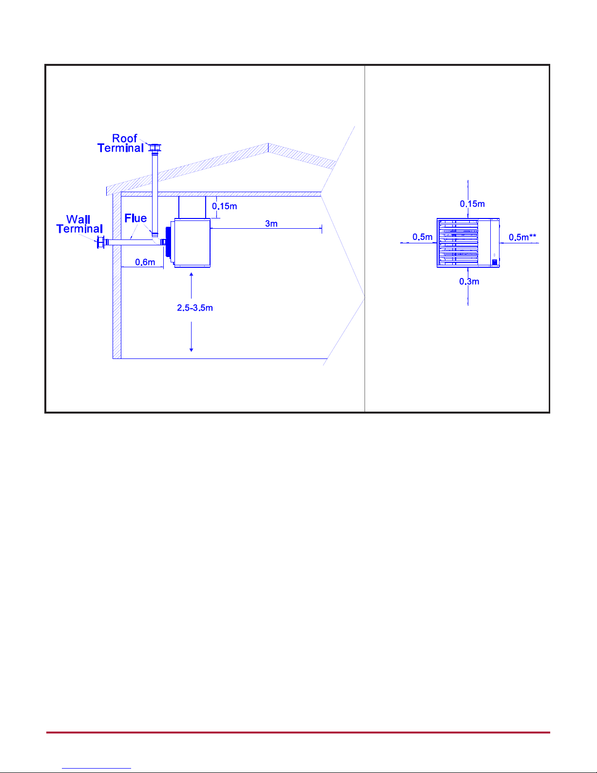
To install the heater in accordance with the clearances to combustibles
of this heater.
To furnish all needed materials not furnished as standard equipment.
To plan the location of supports, flues and air intakes.
To provide access to burners for servicing.
To provide the owner with a copy of this installation, commissioning,
operation and service manual.
To never use heater as support for ladder or other access equipment
and never hang or suspend anything from the heater
To ensure that there is suicient ventilation in the area to comply with
the requirements of all relevant local and national regulations.
To ensure the heater is placed in an approved application.
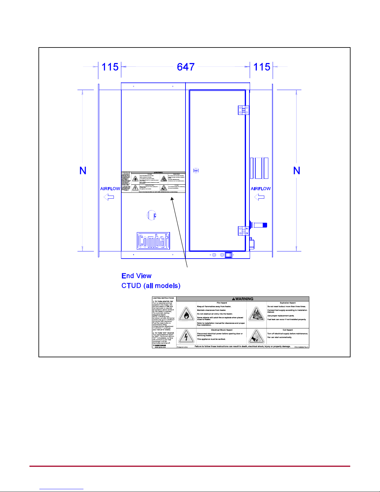
2.1 Laminated Wall Plate
A laminated wall plate is available for the heater as a permanent
reminder of the safety instructions and the importance of the required
clearances to combustibles. Aix the plate by peeling o the backing of
the adhesive strips on the rear surface and position the plate on a wall
near the heater
A copy of the wall plate is illustrated on the back cover. Know your
model number and installed configuration. The model number and
installed configuration are found on the burner and in the Installation,
Commissioning, Operation and Service Manual. Write the largest
clearance dimensions with permanent ink according to your model
number and configuration in the open spaces on the plate.
2.2 Corrosive Chemicals
Combat HVAC Limited cannot be responsible for ensuring that all
appropriate safety measures are undertaken prior to installation; this
is entirely the responsibility of the installer. It is essential that the
contractor, the sub-contractor, or the owner identifies the presence
of combustible materials, corrosive chemicals or halogenated
hydrocarbons* anywhere on the premises.
* Halogenated Hydrocarbons are a family of chemical compounds
characterized by the presence of halogen elements (fluorine, chlorine,
bromine, etc.). These compounds are frequently used in refrigerants,
cleaning agents, solvents, etc. If these compounds enter the air supply
of the burner, the lifespan of the heater components will be greatly
reduced. Warranty will be invalid if the heater is exposed to halogenated
hydrocarbons.
2.3 National Standards and Applicable Regulations
All appliances must be installed in accordance with the latest revision
of applicable standards and local and national regulations. This refers
also to the electric, gas and venting, flueing and insulation ventilation.
Note: Additional standards for installations in public garages, aircraft
hangars, etc. may be applicable.