3pg. ComCo Systems Inc. | 800.533.3794 | www.comcosystems.com 500660 Rev. -
Series
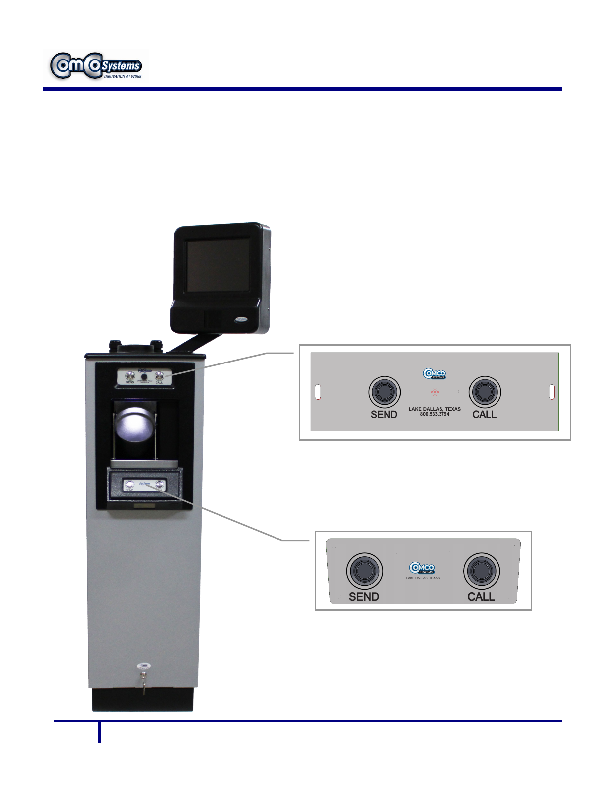
System Features
The Model 522AX is an overhead pressure/vacuum system that utilizes 4.5" tubes and
carriers. The carrier travels from the teller unit to the customer unit under vacuum and
returns under pressure. The blower unit is located inside of the customer unit.
•The Model 522AX is configured with four major subsystems:
1. Single-Sided Chute Teller Unit P/N: 200656
2. Blower Unit: P/N: 201282
3. Customer Unit (CU) P/N: 201283
4. System Controller P/N: 200703
Chute (STC4500)
STC-4500-200656
Doorless operating unit
which is suspended from the
ceiling, typically over the
counter top.
Blower
201282
Features (Ea. Single Pack):
1 High Voltage Control Box
1 Blower for pressure
1 Blower for vacuum
CU-522AX-201283
Fully automatic door
operation with tip tube,
integrated blower module,
and optional 2 way video
SC-521-200703
System Controller