Comco AccuFlo AF10-CE User manual

ComcoInc.2151N.LincolnSt.Burbank,CA91504USA
Tech@comcoinc.com1‐818‐841‐5500

VENTHOSE
VENTHOSE
1‐818‐841‐5500 2 www.comcoinc.com
TableofContents
Simoom®Technology……………………. 3
Set‐UpProcedures……………………… 4‐5
TankOrifice&BypassTube………….... 6
PowderGate®Valve……………………….. 7
AF10‐CEComponents……………………. 8
MaintenanceCounters………………..… 9
Modulator……………………………………… 9
TroubleShooting………………………… 10
ElectricalSchematic………………….… 11
PneumaticSchematic…………………. 12
WarrantyInformation…………………. 13
AccuFlo®Nozzles..………………………. 14
NozzleFixturingGuide…………………. 14
AccuFlo®AF10‐CESpecifications
Model: AccuFlo AF10‐CEStandardTank AccuFlo AF10‐CETTallTank
Shipping
Weight:
30lb.(13.6kg) 30lb.(13.6kg)
Height: 10.5in.(26.7 cm) 15.0in.(38.1cm)
Width: 17.5in.(44.5cm) 17.5in.(44.5 cm)
Depth: 10.0in.(25.4cm) 10.0in.(25.4cm)
AirPressure: 10‐ 125psi(0.7– 8.6bar) 10‐ 125psi(0.7– 8.6bar)
Powder
Capacity:
1liter 2liters
NozzleSizes: Round.015‐ .060in. ø(.38mm– 1.5mm)
Othershapesandsizesavailable.
FacilityRequirements
Inlet AirPressure: 70– 145psi(4.8– 10bar)
AirVolume: Dependingonnozzlesizeandairpressure,consumptionis
typically0.2 – 4.6SCFM(94– 2170cm3/sec.)
AirSupply
Quality:
Driedto‐25° Fdewpoint(200 ppmofmoisture)andoilcontent
filteredto<10ppm
Power
Requirements:
115V60Hz,40W
230V50Hz,40W

Congratulations,theComcoAccuFlo®modelAF10‐CEyouhavepurchasedincorporatesthelatest
developmentinmicro‐abrasiveblasting– SimoomTechnology.
Thispatentedmethodofmixingairandabrasivedeliversasteadyandconsistentstreamof
abrasiveallowingyoutoprocesspartsefficientlyandwithuniformresults.Here’swhyitworksso
muchbetterthanothermicro‐abrasiveblasters.
Activatetheblastandthemodulatoropensandcloses50or60timespersecond(dependingon
localpowersuppliedat50Hzor60Hz),producingpulsesintheairstream.Therapidchangeinair
pressurefluidizestheabrasiveabovetheorifice.Thepowderisthendrawnthroughtheorifice
intothemixingchamberwhereitenterstheairstreamandexitstheAccuFlo®throughthe
PowderGate®valvetravelingouttothenozzle.
Thestrengthofthesemodulatedpulseandthediameteroftheorificedeterminestheamountof
abrasivethatdropsintothemixingchamber.Threemechanismsenableyoutochangetheamount
ofabrasiveintheairstream:thetankorifice,abrasiveblendandbypasstube.
TankOrifice:Alargerorificeincreasesabrasiveflow.Inmostcasestheorificeshouldbeatleast5
timesthesizeoftheaverageparticlesize,butnotlargerthanthenozzle.
BypassTube: Thebypasstubecreatesanalternatepathforthemodulatorpulses,bypassingthe
orifice.Alargerbypasstubedampenstheimpactofeachpulse,reducingmediaflow.
AbrasiveBlend:Theabrasiveblendchangesthestrengthofthepulsebyallowingsomeairto
bypassthemodulator.Withlessairpassingthroughthemodulator,thepulseweakensandless
abrasiveisfedintotheairstream.Theabrasiveblendvalveallowsyoutofinetunetheabrasive
flow.
FormoretechnicaldetailsonSimoom®Technology,seeUSpatent#7,297,048.
Simoom®Technology

1‐818‐841‐5500 4 www.comcoinc.com
1. Removethetankcover.
2. Fillthetankwithpowder.Donotfill
abovethetopofbypasstube.
3. Replacethetankcoverandsecure(only
¾turnrequired).
MakeConnections
AddAbrasive
VENTHOSE
ISROUTED
THROUGH
THEVENT
PINCH
INLETAIRFITTING
THEABRASIVEHOSEFROMTHE
POWDERGATEVALVERUNSDIRECTLY
TOTHENOZZLE.
DONOTROUTETHISHOSE
THROUGHTHEVENTPINCH!
1. PlacetheComfortGriphandpieceinsidetheworkchamber.
2. Placetheopenendoftheventhoseintothebackoftheworkstationorintothedust
collectorhose.
3. Connectthepowercordandtheblastcontrolcable.
4. Connecttheairsupplytothe“AirIn”fitting(using¼"tubingprovidedintheaccessorykit.)
TONOZZLE(S)

CablingandcontroldependsonhowtheuserdesirestocontroltheAF10‐CE.Usetheabovetable
todeterminewhichcabletouse.IftheAF10‐CEispairedwithanAutoFillunit,refertotheAutoFill
manualforadditionalwiringinformation.
BlastControl:Pin1provides115VACpowerfromtheAccuFlo.Thehostmustprovideaswitchto
putthisvoltagebackintoPin2,whichwillcausetheblastertoblast.WhenPin2isleftfloating,
theblasterwillnotblast.200mAofcurrentistypical.
PE: Pin4providesanoptionalbondingpathtoPrimaryEarththroughtheAccuFlo.Ifthehostis
otherwisebondedtoPE,donotusethispin.
RegulatorControl:Theregulatormustbepoweredby24vdcthroughPin7andgroundthroughPin
6.Theregulatorrequires60mAofcurrent.Theblastpressureissetbyprovidinga0‐10vdcsignal
atPin8,whichcorrespondstoapressureof0‐148psi.Theinternalresistanceoftheregulator’s
inputis100ohmsminimum.
AF10‐CECablesandControllers
A10‐CEControlConnector

1‐818‐841‐5500 6 www.comcoinc.com
TANK ORIFICE
MB1409‐x
BYPASSTUBE
MB2265‐x
TANKASSEMBLY
MB2200‐10(Standard)
MB2200‐20(Tall)
BypassTubeChart
TANK ORIFICE
MB1409‐
StandardTank ‐1C‐1B‐1A
TallTank ‐2C‐2B‐2A
‐18
‐25
‐30
1=LeanMixture(lessabrasive)
5=RichMixture(moreabrasive)
TankOrificeandBypassTube
WehaveconfiguredtheAccuFlo®foryour
particularapplication.
Startwiththesesettings.
Youhavetheoptiontoadjustsettings.Minor
changesinpowderconcentrationshouldbemade
withtheAbrasiveBlendControlonthefrontpanel.
Formoresignificantchanges,theabrasive
concentrationintheairstreamcanbemade
leaner (lessabrasive)orricher (moreabrasive)by
changingthetankorificeandthebypasstube.
ContactaComcoTechSupportSpecialistfor
informationonadditionaloptions.
•Changethetankorificeusinga¼"nutdriver.
•Unscrewthebypasstubeandliftitoutofthe
sleeve.Usingthechartbelow,selectthetube
youdesireandinsertitinthesleeve.
Fingertightenonly;donotforce.
BYPASSTUBE
MB2265‐
123
234
345

ThePowderGate®NoseandOutputFittingshouldbereplacedafter250,000cycles.
•UnscrewtheOutputFittingwitha¾"wrench.
•Withpliers,gentlypullthewornNosefromshaft.
•PressonnewNose.
•InstallthenewOutputFitting.
•ConnectthetubingwiththeblueQuicknut.
PowderGate®Valve

AF10‐CEComponents
1‐818‐841‐5500 8 www.comcoinc.com

Foreasiermaintenancetherearetwo
countersonthefrontpanel.
TheCYC countsthenumberofblastcycleson
theAccuFlo (eachtimethePowderGate®
valveopens.)
Abrasivetypeandblastpressurewillimpact
maintenancefrequency,buttypical
configurationswilllastmorethan250,000
cyclesbeforeneedingmaintenance.
TheHRS counterrecordsthenumberofblast
hours(i.e.actualtimethemodulatorhas
operated.)
ToreplacetheAccuFlo®AF10‐CE
modulator:
•Disconnect3coloredtubesfromthe
modulatorandtheelectricalplug
fromfrontpanel.
•Removethetwoscrewsholdingthe
modulatortothebracketusinga
Phillipsscrewdriver.
•Installnewthemodulatorinreverse
order,makingsurethetwogrommets
remaininthebracket.
AccuFlo®AF10‐CEModulator
MODULATOR
MB2250‐1(115V)
MB2250‐2(220V)
MaintenanceCounters
Yourmaintenancerequirementsmayvarywithyourapplication.
Themodulatorshouldbereplacedafter2000hoursofoperation.

1‐818‐841‐5500 10 www.comcoinc.com
Iftheunitdoesnotpressurizewhenyouturniton:
•Istherepowertotheunit?Doesthelightonthepowerswitchilluminate?
Ifnot,checkthepowercordconnectionsatthebackoftheunitandatthepowersource.Check
thefuse.
•Istheairlineconnected?Aretheupstreamvalvesopen?
Checktheinletairsupply.
•Doyouhearairescapingfromtheunitwhenitisturnedon?
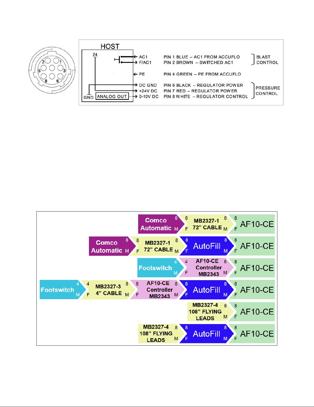
Checkthattheinletair,venthose,andabrasivehoseexitingthePowderGate®valveare
connectedproperly.Seetheset‐upguideonpages4‐5.Makesurethetankcoverissecurely
fastened.
Ifairispassingthroughthenozzle,butnoabrasive;orifthecuttingactiondecreases:
•Isthepowdertankempty?Refill.
•Istheabrasiveinthetankdampandstickingtothewalls?
Replacewithfreshpowder.Checkthatyourairdryerisworkingproperly.
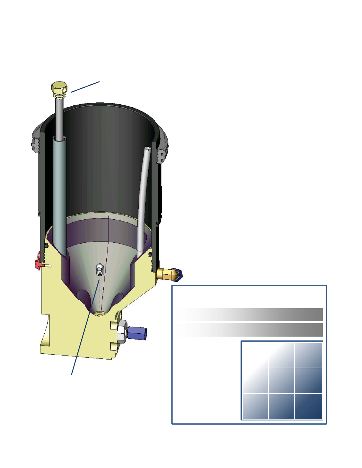
•Isthetankorificeplugged?
Emptypowder,removeorifice,andinspect.Checktoseethatyoursupplierofabrasivepowder
isprovidinghighqualitymaterial.
FordetailsseetheSupportsectiononourwebsite.
•Isyourmodulatorfunctioningproperly?
Youshouldhearabuzzingsoundwhentheblastisactivated.Ifnot,themodulatormayneedto
bereplaced.ForfurtherdetailscontactTechnicalSupport.
Ifnothinghappenswhentheblastisactivated:
•Isthenozzleplugged?Removeandinspect.
•IsthePowderGate®valvefailingtoopen?ContactTechnicalSupport.
IfyoususpectthePowderGate®valveisnotclosingcompletely:
WhenthePowderGate®valvecloses,placeafingerovertheendofthenozzlefor3seconds.
Whenyouremoveyourfinger– isthereasmallpuffofair?Ifso,therearetwopossibilities:
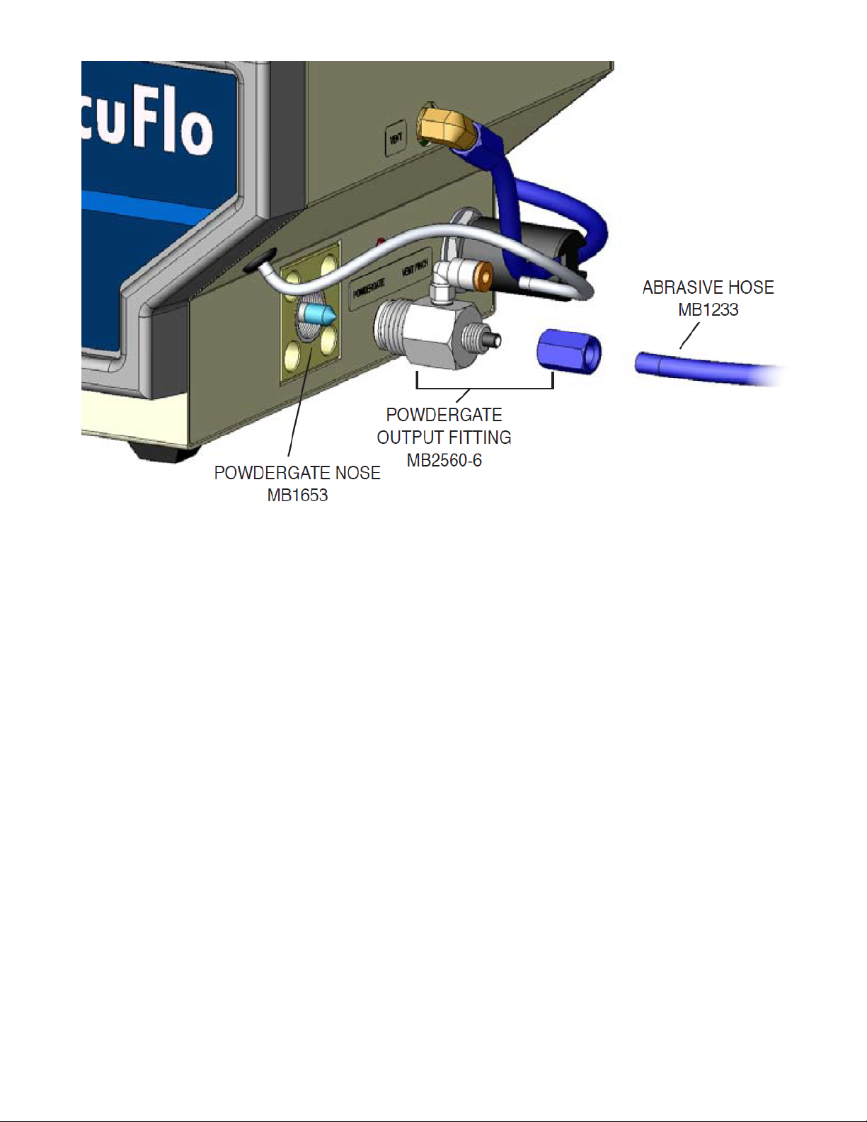
•ThePowderGate®noseiswornandcanbereplacedasdescribedabove.
•Theabrasivemixturemaybetoorich.ReduceAbrasiveBlendadjustmentonfrontpanel,or
checktheBypassTubeChartforaleanermixturetohandleyournozzlesize.
Troubleshooting
Contaminationoftheabrasivepowderfrom
moistureand/oroilisoneofthemost
commonproblemsassociatedwithmicro‐
abrasiveblasting.
Moisturewillcausethepowderto“clump
up,”preventingitfromflowingfreelyfrom
thetank.
Oilintheairsupplywillnotonlyaffect
abrasiveflow,itcanalsocausemajor
componentfailureswithinyourblaster,
resultingincostlyrepairs.
Toavoidmoistureandoilcontamination,run
yourairsupplythroughapositiveairdryer
equippedwithanappropriateoilfilter.
PreventMoistureandOilContamination

AF10‐CEElectricalSchematic
Rev.12.7.21

AF10‐CEPneumaticSchematic
1‐818‐841‐5500 12 www.comcoinc.com

TheComcoWarranty
ComcowarrantsthattheAccuFlo®modelAF10‐CEwillbefreefromalldefectsinmaterialand
workmanshipundernormaluseforaperiodofoneyearfromthedateofpurchaseor2,000hours
ofnormaloperation,whichevercomesfirst.
ThewarrantyperiodbeginswhentheequipmentshipsfromtheComcofacilityandappliestothe
originalowneronly.Comco isnotliablefordamagesfromanycauseoruseofsuchequipment
beyondthecostofrepairinganydefectiveparts.
Iftheequipmentfailstoperformsatisfactorilyduringthewarrantyperiod,Comcohastheoption
todoanyoneofthefollowing:1)Sendreplacementpartstothecustomertobeinstalledbythe
customer;2)Repairtheunitatthecustomer’sfacility;or3)Requestthattheunitbereturnedto
theComcofactory.AnyreplacementpartsshallbefurnishedbyComcowithoutcost,F.O.B.the
ComcofactoryinBurbank,California,providedthatComcoisnotifiedofthedefectwithinthe
warrantyperiod.AnydefectivepartsshallbereturnedtoComcoforinspectionandanalysis.
Exclusions
Theabovewarrantydoesnotapplytodefectsorproblemsresultingfromimproperorinadequate
maintenancebythecustomer;unauthorizedmodificationormisuse;failuretofollowthe
operatinginstructions;theuseofanysuppliesorparts,includingbutnotlimitedtonozzles,
powders,andattachments,notmanufacturedorsuppliedbyComco.
Thewarrantyalsodoesnotcoverproblemsresultingfromimproperorinadequatefacilities
(contaminatedair;improperpower)oritemsthatshouldbeexpectedtowearinnormal
operation,suchasnozzles,abrasives,tubing,orfittings.
ThisisComco’sonlywarrantyandisinlieuofallotherwarrantiesofmerchantabilityandfitness
foranyparticularpurpose.Norepresentationsorwarrantiesareauthorizedexceptasherein
stated.
AlwaysoperatetheAccuFlo®blasterinan
appropriateworkstationwithdustcollection.
Neverblasttowardsomeone’sfaceoreyes.This
isapressuredevice.
TheLexanwindowonthetankcoverisabrasion
resistant.However,contactwithcertainchemicals
canweakenthecoverandcauseittocrack.
Inspectthecoverdailyandreplaceimmediatelyif
cracksdevelop.
RefertoComcoTechnicalSupportforfulldetails.
WARNING
MAXIMUMBLASTSETTINGONYOURBLASTER
Neveroperateanymicro‐abrasiveblasterwith
theairpressureregulatorfullyopen.Check
yourcompressorsettingstodeterminetheair
pressurelevelitusestotriggerthere‐pressurize
cycle.Theblastpressuresettingonyourblaster
shouldalwaysbesetat10psibelowthispoint,
whichisthelowestsupplypressurecoming
fromyourcompressor.Iftheinletpressure
dropsbelowtheblastpressuresetting,airand
abrasivewillflowbackwardthroughyour
systemanddamagecriticalcomponents.

ComcoInc.2151N.LincolnSt./Burbank,CA91504,USA
818‐841‐5500/www.comcoinc.com
TS702‐CE1.7.22eCopyright2022,ComcoInc.,AllRightsReserved
ForadditionalnozzleoptionscontactComcoTechSupport
FixturedNozzle
RemovingandReplacingNozzle
Hi/PerformanceAccuFlo®NozzleOptions
MB2520‐18(.018"Dia.) MB2520‐30(.030"Dia.)
MB2520‐46(.046"Dia.) MB2520‐60(.060"Dia.)
Thelifeofyournozzlewilldependonthetypeofabrasiveandairpressureyouuse.
Checkthenozzleforwearonaregularbasis.
8‐32SetScrew
MB1483‐3Quicknut
Hi/Performancenozzle
.375
(Recommended)
8‐32tappedhole
toØ.1885 hole
(setscrew)
Abrasivehose
Ø.1885+.0005/.000
MB2599
ComfortGrip handpiece
Table of contents
Other Comco Industrial Equipment manuals