Comco DirectFlo DF1400 Series Operation manual

Operation and Service Instructions
DirectFlo™ DF1400
Issue Date: January 2009
This manual covers all variations of the DF1400 series
(DF1400-1, DF1400-2, ETC)
Comco Inc.
2151 N. Lincoln Street
Burbank, California 91504
USA
Phone: 818-841-5500
FAX: 818-955-8365
www.comcoinc.com
Book P/N PF1430
File: DF1400.doc

Comco Inc. ii Issue Date: January 2009
Table of Contents
The Comco Warranty ............................................................................................iv
Safety Precautions ................................................................................................v
Chapter 1: The DirectFlo DF1400 .............................................................1-1
This chapter introduces you to the basic unit, including its
description, principles of operation, and detail specifications.
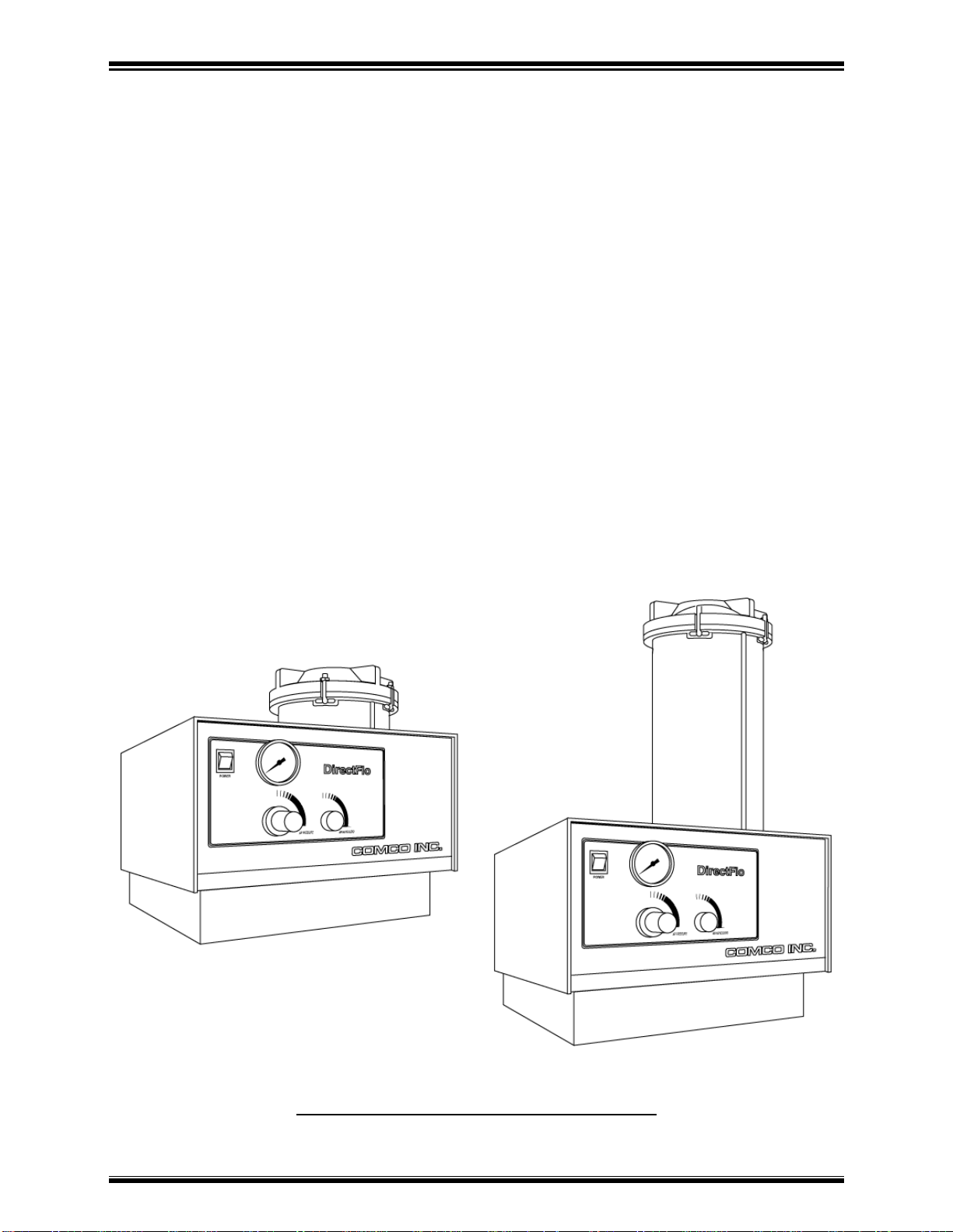
Overview....................................................................................................1-2
Figure 1-1, DirectFlo DF1400.........................................................1-2
How The DirectFlo Works..........................................................................1-3
Figure 1-2, DirectFlo Pressurized...................................................1-3
Figure 1-3, Modulator Open............................................................1-4
Figure 1-4, Modulator Closed.........................................................1-5
Detail Specifications...................................................................................1-6
Chapter 2: Getting Started........................................................................2-1
This chapter tells you what you need to have and what you
need to do to set up the DirectFlo.
The Proper Work Area...............................................................................2-2
Figure 2-1, Micro-abrasive Blasting System Requirements ............2-3
Figure 2-2, DirectFlo Reference Sheet...........................................2-4
What You Received with the DirectFlo.......................................................2-5
Basic Components of the DirectFlo............................................................2-6
Figure 2-3, External Component Locations.....................................2-7
Setup and Test ..........................................................................................2-8
Figure 2-4, Tank Inspection............................................................2-9
Chapter 3: Using the DirectFlo.................................................................3-1
This chapter discusses the selection of key operating
parameters such as abrasives and nozzles; and tells you
how to operate the DirectFlo for maximum efficiency.
Essence of Micro-Abrasive Blasting...........................................................3-2
Table 3-1, Factors Affecting Abrasive Blasting...............................3-3
Abrasive Selection.....................................................................................3-4
Table 3-2, Abrasives and Their Applications...................................3-5
Tank Orifice and Nozzle Selection .............................................................3-6
Table 3-3, Orifice Selection Chart...................................................3-7
Figure 3-1, Changing the Tank Orifice............................................3-7
Figure 3-2, Changing the Nozzle....................................................3-8
Table 3-4, Nozzle Chart..................................................................3-9
General Operation of the DirectFlo ............................................................3-12
Figure 3-3, Filling the Abrasive Tank..............................................3-13
Figure 3-4, Controls and Indicators.................................................3-14

Comco Inc. iii Issue Date: January 2009
Table of Contents
Chapter 4: Maintenance............................................................................4-1
This chapter tells you what you need to do to keep the
DirectFlo operating properly.
Normal Maintenance..................................................................................4-2
Table 4-1, Maintenance Intervals ...................................................4-3
Parts Subject to Normal Wear....................................................................4-4
Figure 4-1, Moving the Hose in the Vent Pinch...............................4-4
General Maintenance.................................................................................4-7
Figure 4-2, Regular Maintenance Items..........................................4-8
Auxiliary Equipment...................................................................................4-9
Moisture.....................................................................................................4-10
Chapter 5: Trouble-shooting and Repair.................................................5-1
This chapter tells you what to do if you have a problem with
the DirectFlo.
Trouble-shooting........................................................................................5-2
Customer Service ......................................................................................5-2
How to Order Replacement Parts ..............................................................5-3
Common Problems, Causes, and Solutions...............................................5-4
Table 5-1, No Air Flow....................................................................5-4
Table 5-2, No Abrasive Flow ..........................................................5-5
Clogging ....................................................................................................5-6
Tank Cover................................................................................................5-7
Replacing the Abrasive Hose and Fittings..................................................5-8
Figure 5-1.......................................................................................5-9
Inspecting and Repairing the PowderGate.................................................5-13
Figure 5-2.......................................................................................5-13
Inspecting and Repairing the Modulator.....................................................5-15
Figure 5-3, Modulator Assembly.....................................................5-16
Air Pressure Regulator...............................................................................5-17
Chapter 6: Optional Equipment and Manual Supplements....................6-1
This chapter details optional equipment available on the DirectFlo,
and the use and servicing of these options.
Appendices
This appendix presents parts lists, drawings and schematics
for the DirectFlo DF1400.
Appendix A: Parts Lists ........................................................................................A-1
Major Assemblies and Principal Parts........................................................A-2
Standard Accessory Parts..........................................................................A-5
Recommended Spares..............................................................................A-6
Appendix B: Drawings and Schematics................................................................B-1

Comco Inc. iv Issue Date: January 2009
Welcome!
Welcome to the User’s Manual for the Comco DirectFlo™ model DF1400
Micro-abrasive Blaster! You have purchased the finest micro-abrasive blaster
available today, and this manual is designed to help you set up, operate, and
maintain the DirectFlo™ DF1400.
NOTE: Prior to setting up and operating your DirectFlo, the operator
and the department supervisor should carefully review this
entire manual.
The Comco Warranty
Comco warrants that the DirectFlo™ DF1400 will be free from all defects in material and
workmanship under normal use for a period of one year from the date of purchase or
2,000 hours of normal operation, whichever comes first.
The warranty period begins when the equipment ships from the Comco facility and
applies to the original owner only. Comco is not liable for damages from any cause or
use of such equipment beyond the cost of repairing any defective parts.
If the equipment fails to perform satisfactorily during the warranty period, Comco has the
option to do any one of the following: 1) Send replacement parts to the customer to be
installed by the customer; 2) Repair the unit at the customer’s facility; or 3) Request that
the unit be returned to the Comco factory. Comco shall furnish any replacement parts
without cost, F.O.B. the Comco factory in Burbank, California, provided that Comco is
notified of the defect within the warranty period. Any defective parts shall be returned to
Comco for inspection and analysis.
Exclusions
The above warranty does not apply to defects or problems resulting from improper or
inadequate maintenance by the customer; unauthorized modification or misuse; failure
to follow the operating instructions; the use of any supplies or parts, including but not
limited to nozzles, powders, and attachments, not manufactured or supplied by Comco.
The warranty also does not cover problems resulting from improper or inadequate
facilities (contaminated air, improper power) or items that should be expected to wear in
normal operation, such as nozzles, abrasives, tubing, or fittings.
This is Comco’s only warranty and is in lieu of all other warranties of
merchantability and fitness for any particular purpose. No representations or
warranties are authorized except as herein stated.

Comco Inc. v Issue Date: January 2009
Safety Precautions
General Safety Considerations
The DirectFlo has been designed to be safe to operate when used properly. Any
device that is pressurized and requires electrical power, however, requires that
certain safety precautions be observed to avoid potentially hazardous situations.
The primary safety-related issues involved in the use of the DirectFlo are listed
below and addressed in detail on the following pages.
1. Working with a device that is pressurized.
2. Working with an electrical device.
3. Working with a device that uses abrasive powders that could be
potentially dangerous if inhaled or ingested in large quantities or
put in constant contact with the skin.
4. General issues involved in operating machinery.
Working with a Device that is Pressurized
The DirectFlo uses pressurized air to perform its basic function. While Comco's
blasting machines incorporate relief valves and check valves to minimize the risk
of an accident related to air pressure, Comco also recommends the following:
√The air supply system should have a shutoff valve located
upstream of the blasting machine so that the supply pressure can
be turned off independently of the blaster.
√Pressure relief valves should be incorporated into the supply
system to minimize the risk from system over pressure.
√Anyone who will use the DF1400 should be trained in its basic
operation.
√The DirectFlo should always be turned OFF and vented prior to
performing any maintenance.
√When replacing parts during maintenance, use only Comco parts
and verify that all installations are correct before using the
DirectFlo.
Improper set-up or use of the DirectFlo DF1400 may result in a condition that could be
hazardous. All fittings and covers must be properly installed and tightened in order to
minimize any hazard.

Comco Inc. vi Issue Date: January 2009
Working with an Electrical Device
The electrical hazards associated with the DirectFlo are minimal, since all
primary electrical components are inside the primary housing. However, the
operator should take precautions that apply to any electrical device that has a
power cord that plugs into an electrical outlet. These precautions include:
√Verify the proper operating voltage on the DirectFlo by checking
the voltage select switch located on the back of the unit.
√Before plugging the power cord into an electrical outlet, examine it
for evidence of damage such as cracked, worn, or torn insulation;
exposure of bare wires; or bent tines on the plug.
√Ensure that the machine is never operated near water or while it is
wet.
√Always verify that the power switch is in the OFF position when
the machine is not in use for long periods of time.
When working inside the DirectFlo housing, there is the possibility of electrical
shock. To minimize this hazard, Comco recommends the following:
√Unplug the unit from facility power any time the machine’s cover
will be removed.
√Do not operate the DirectFlo with its cover removed.
√Keep the interior of the DirectFlo clean of dust, powder, and any
foreign object or substance that could conduct electricity.
CAUTION: Some abrasive powders are conductive
and may present a hazard if allowed
to accumulate inside the machine.
Working with the Abrasive Media
The DirectFlo uses several types of abrasive media that should not be inhaled or
ingested in large quantities or maintained in prolonged contact with the skin.
When working with the abrasive media, Comco recommends the following:
√Do not direct the abrasive blast on bare skin or face/eyes.
√A WorkStation and dust collector must be used in conjunction
with the DirectFlo. If you must blast outside a WorkStation, a full
facemask and oxygen supplied respirator and hand protection are
required per NIOSH (National Institute for Occupational Safety
and Health).
√Handling operations such as repackaging or refilling of the
abrasive media should only be performed in well-ventilated areas
and with proper care to minimize dust in the eyes or breathing
passages. Always use a dust respirator for dust protection when
exposed to dust clouds. The 3M respirator #8710 is NIOSH/MSHA
approved for these types of abrasive handling operations

Comco Inc. vii Issue Date: January 2009
Working with the Abrasive Media (cont’d)
√Certain abrasive media, such as glass beads, can present a
slipping hazard if they are spilled on the ground. Always clean up
spilled abrasive, and place appropriate warning signs in areas
where the abrasive will be on the ground (such as during long-
term operation).
√Abrasive powders, particularly glass beads and plastic, may
generate static charges. To minimize the risk of electrostatic
discharge, ground the DirectFlo and the WorkStation. In some
instances the operator may also wish to use grounding straps
(Wrist-Stats™ or equivalent).
√Flammable powders, such as walnut shell and plastic, may pose a
fire or explosion hazard. Always use a vigorous dust extraction
device to prevent hanging dust clouds.
√After using the DirectFlo, or after handling any of the abrasive
media, wash your hands before touching or rubbing your eyes.
√Gloves may be necessary for operators who are sensitive to
powders or dust on their skin.
√Some powders, if allowed to collect inside the machine, may
cause electrical shorts.
Material safety data sheets (MSDS’s) for all abrasives distributed by Comco are
available from the Comco factory. Every powder shipment includes an MSDS.
Contact the Comco Customer Service department to obtain extra copies of any
MSDS.
Avoiding Hazards Associated with Operating Machinery
√Place the DirectFlo securely on a solid workbench or counter so
that the unit cannot tilt or fall over.
√Always secure the nozzle-end of the abrasive blast hose before
pressurizing a blasting unit. An unsecured hose may whip around
and cause injury or damage.
√Keep fingers out of the hose pinch.
√When working inside the cabinet, avoid possible sharp edges and
remember that solenoids on valves can become hot.
√Set up the DirectFlo and WorkStation so that it is ergonomically
correct to allow safe and comfortable use by all operators.
√Route the foot pedal cord from behind the bench to prevent it from
becoming a possible trip hazard.

Comco Inc. viii Issue Date: January 2009
Avoiding Hazards Associated with Operating Machinery (cont’d)
The following warning labels/pictograms are utilized in the DirectFlo CE
(European) versions:
Symbol
Meaning
ELECTRICAL HAZARD
HAND PROTECTION RECOMMENDED WHERE
APPROPRIATE
EYE PROTECTION RECOMMENDED WHERE
APPROPRIATE
RESPIRATORY PROTECTION RECOMMENDED
WHERE APPROPRIATE

DirectFlo DF1400 Chapter 1: The DirectFlo 1400
Comco Inc. 1-1Issue Date: January 2009
Chapter 1: The DirectFlo DF1400
In This Chapter
A general description of the DirectFlo
How the DirectFlo works
Detail specifications

DirectFlo DF1400 Chapter 1: The DirectFlo 1400
Comco Inc. 1-2Issue Date: January 2009
STANDARD
HIGH CAPACITY
Overview
The Comco DirectFlo Model DF1400 is a bench-top machine that delivers a precisely
controlled stream of micro-abrasive particles at high velocity. With the appropriate
abrasive powder and the necessary adjustments, it will clean, deburr, cut or drill any
material, particularly hard or brittle ones. Since dry air is used as a propellant, it is a
relatively clean process.
The machine is essentially simple and uncluttered (see Figure 1-1). It consists
principally of an inlet air valve (rear panel), air pressure regulator with gage, modulator
(internal), abrasive powder tank, and mixing chamber. The abrasive PowderGate®
valve assembly to stop and start the abrasive flow, the footswitch to actuate it, and a
handpiece that holds the precision nozzle, complete the machine. All the component
parts are manufactured to the highest standards and are designed for maximum life
consistent with reasonable cost. The basic mechanisms employed, particularly the
modulator, are covered by the following patents:
United States: 3,053,016 Johnson
3,084,484 Hall
3,638,839 Weightman
United Kingdom: 1,243,294
Additional United States and foreign applications for patents are pending.
Figure 1-1: The Comco DirectFlo DF1400

DirectFlo DF1400 Chapter 1: The DirectFlo 1400
Comco Inc. 1-3Issue Date: January 2009
How the DirectFlo Works
As shown in Figure 1-2, below, when the DirectFlo Power Switch on the front panel is
initially turned “ON”, supply air enters through the energized air valve at the back of the
unit. The supply air passes through a regulator that allows the operator to control the
system pressure, as indicated by the gage on the front of the machine.
The regulated air then passes through an open, or de-energized, modulator assembly
and into the mixing chamber and abrasive tank. Air cannot escape through the nozzle
because the PowderGate (or shut-off) assembly is closed. The air pressure inside the
system builds up until it reaches the regulated pressure.
Figure 1-2: DirectFlo, Pressurized
The DirectFlo, as shown in the illustration above, is now pressurized and ready to use.
To operate the DirectFlo from this point would simply require picking up the nozzle,
pointing it at the item to be blasted, and depressing the footswitch to begin blasting.
What happens when the machine is actually in operation is explained on the following
pages.

DirectFlo DF1400 Chapter 1: The DirectFlo 1400
Comco Inc. 1-4Issue Date: January 2009
How the DirectFlo DF1400 Works (cont’d)
Stepping on the footswitch used to operate the DirectFlo causes two things to happen:
1) The PowderGate assembly opens, which allows air to flow from the
nozzle. Refer to Figure 1-3, item 1.
2) An electrical signal is sent to the coil of the modulator assembly which
energizes and de-energizes it 60 times every second. Refer to Figure 1-4,
item 2.
At the beginning of the operating cycle (as shown in Figure 1-3, below), the hose pinch
is opened. Before the modulator has had a chance to energize, regulated air flows
freely through the open modulator valve, the mixing chamber, and out the nozzle.
Figure 1-3: Modulator Open
Since the air flowing from the regulator into the mixing chamber is at basically the same
pressure as that in the tank, the upward force of the air keeps the abrasive in the tank.
At this point, little or no abrasive is being injected into the air stream.

DirectFlo DF1400 Chapter 1: The DirectFlo 1400
Comco Inc. 1-5Issue Date: January 2009
How the DirectFlo DF1400 Works (cont’d)
In the second half of the operating cycle, the modulator coil becomes energized. This
pulls the modulator core against the seat (see Figure 1-4, below), shutting off the airflow
from the regulator. The pressure in the mixing chamber now decreases because the
downstream end of the system, at the nozzle, is open to the atmosphere.
Since the pressure in the mixing chamber is lower than the pressure in the abrasive
tank, the two pressures try to balance. Air pressure inside the abrasive tank pushes a
small amount of abrasive through a precision orifice at the bottom of the tank, into the
mixing chamber and out through the nozzle.
Figure 1-4: Modulator Closed
When the next cycle begins, the modulator is again de-energized, and opens to allow
pressurized air to freely flow into the mixing chamber and out the nozzle. This forces air
back into the abrasive tank, stabilizing the pressure between the tank and the mixing
chamber (refer back to Figure 1-3).
Each cycle happens very quickly; 50-60 times per second. The end result of this
“stop/start” action of the modulator is a consistent stream of abrasive out the nozzle, as
long as the footswitch is depressed. Releasing the footswitch stops the modulator from
cycling and causes the PowderGate to close the outlet air hose.
The only way for the abrasive powder in the tank to reach the mixing chamber is via the
orifice at the bottom of the tank. By changing the size of the tank orifice, you can
change the amount of abrasive that enters the mixing chamber, and thus change the
abrasion or cutting rate at the nozzle. Additional information regarding the tank orifice,
nozzle sizes, abrasives, and other variables in the abrasive blast process is presented in
Chapter 3 of this manual.

DirectFlo DF1400 Chapter 1: The DirectFlo 1400
Comco Inc. 1-6Issue Date: January 2009
Detail Specifications
Abrasive (see Chapter 3)
Type Selected powder, smooth to sharp, soft to hard
Size 20 to 300 Microns
Nozzles (see Chapter 3)
Material Highest quality Tungsten Carbide
Sizes, Round 0.030 to 0.080 in. Dia. (0.8 to 2 mm)
Sizes, Rect. 0.008 x 0.125 to 0.016 x 0.190 in. (0.2 x 3.2 to
0.4 x 4.8 mm)
Configuration Straight or Right Angle (Multiple, Optional)
Air Type Nitrogen, CO2, or Dry Compressed Air
Supply Pressure 90 to 140 PSIG (6.2 to 9.6 Bars)
Working Volume, Max 6 SCFM (170 SLM) Typical [1]
Working Pressure 40 to 140 PSIG (2.7 to 9.6 Bars)
Moisture 200 PPM Max
Oil 10 PPM Max
Particles 5 Microns Max
Electrical
Voltage[2] 115 or 230 (+10, -20) VAC
Frequency 50/60 Hz
Power Less than 100 Watts
Physical
Width 18 in. (46 cm)
Depth 16 in. (40 cm)
Height [Tall tank model] 17 in. (43 cm) [25.2 in. (64 cm)]
Weight [Tall tank model] 64 lbs. (29.5 kg) [72 lbs. (32.6 kg)]
Tank Size [Tall tank model] 200 in3(3300 cm3) [400 in3(6600 cm3)]
Tank Capacity, abrasive 10 lbs. (4.5 kg) [20 lbs. (9 kg)]
During normal operation, employing a 0.060" diameter nozzle, a 0.025" diameter tank
orifice, and 25 micron aluminum oxide powder; a full tank of powder, approximately 10
lbs. (standard tank), will last about 6 - 9 hours of actual blast time; air will be used at
about 250 standard cubic feet per hour (SCFH) at 80 psig; and nozzle life will be 8 to 35
hours depending on the amount of wear that can be tolerated.
[1] Units supplying abrasive to multiple nozzles may require up to 12 SCFM.
[2] Operating voltage specified by order and is shown on nameplate.

DirectFlo DF1400 Chapter 2: Getting Started
Comco Inc. 2-1 Issue Date: January 2009
Chapter 2: Getting Started
In This Chapter
The work area required to properly use
the DirectFlo
What you received with the DirectFlo
Basic components of the DirectFlo
Setting up and testing the DirectFlo

DirectFlo DF1400 Chapter 2: Getting Started
Comco Inc. 2-2 Issue Date: January 2009
The Proper Work Area
The DirectFlo should be used in an environment that:
Provides adequate ventilation.
Provides adequate lighting both inside and outside the primary
WorkStation. Comco recommends that the general environment
be illuminated with at least 50 decaluxes and that the interior of
the WorkStation be illuminated with a minimum of 125 decaluxes.
Is between 68°F and 85°F, with less than 40 percent relative
humidity.
The DirectFlo is intended for use in a factory or shop environment. It is not designed for
use where it could be exposed to rain, caustic chemicals, heavy vibration, and other
non-standard environments. Use in applications other than those described in this
manual may result in hazardous conditions and void the warranty.
Since it is impossible to achieve 100% containment of the abrasive within the system, it
is not recommended for use in a “clean room”.
In addition to the DirectFlo, typically three additional elements are needed for proper
micro-abrasive blasting: a WorkStation, a dust collector, and a dry air supply. The
following paragraphs explain the importance of each of these items. Refer to figure 2-1
to see how these items work together as a complete system.
WorkStation
A suitable hood or box providing a means of working with the abrasive material without
contaminating the atmosphere of the room is required. It must protect the operator's
face and provide adequate light. The Comco WS2200 and WS6000 WorkStations are
designed for this purpose.
Dust Collector
In order to remove the spent abrasive, a suitable industrial dust collector is required.
These dust collectors have both high airflow and large filter areas to keep work areas
clean and dust free. The Comco DC2100 is a suitable dust collector for most micro-
abrasive blasting applications. In heavy usage, multiple blaster, and automated
applications, the continuous duty DC3000 dust collector is recommended.
Air Supply
The propellant required for the abrasive is compressed air or neutral gas that meets the
Detail Specifications outlined in Chapter 1. Comco has a complete line of air dryers for
shop (compressed) air supplies that will meet or exceed those specifications.
Bottled gas such as CO2or nitrogen provides clean, dry air, and may be used if shop air
is not available. However, depending on operating conditions, a 50 lb. bottle of gas will
only last 3-4 hours. Bottled gas does not require air dryers, but may require special
regulators. Contact Comco for more information.

DirectFlo DF1400 Chapter 2: Getting Started
Comco Inc. 2-3 Issue Date: January 2009
DIRECTFLO™
DF1400
WORKSTATION
AIR FILTER
& DRYER
ABRASIVE
MEDIA
DUST
COLLECTOR
Figure 2-1: Micro-abrasive Blasting System Requirements
Electric Power
A source of 115 or 230 VAC, 50/60 Hz, capable of providing 100 watts is required for the
DF1400. If the WS2200 or WS6000 WorkStation is used, it requires 40 watts. The
DC2100 Dust Collector, if used, requires about 16 amps (115 VAC) for its 1-HP motor.
Actual voltage required for each machine will be found on the nameplate.

DirectFlo DF1400 Chapter 2: Getting Started
Comco Inc. 2-4 Issue Date: January 2009
Figure 2-2: DirectFlo Reference Sheet
Figure 2-2 is an illustration of the Reference Sheet that comes with your DirectFlo. It
contains important information you can use to get the most out of your investment. Keep
it nearby and refer to it often. However, it cannot substitute for the comprehensive data
found in this manual. Prior to setting up and operating your DirectFlo, the operator and
the department supervisor should carefully review this entire manual.
QUICK START INSTRUCTIONS
You may use this tip sheet to quickly get your DirectFlo set up and ready to operate, and as a ready reference for common questions regarding the
operation of the DirectFlo. Keep it nearby and refer to it often. For complete details on the DirectFlo, Comco strongly urges you to read the manual
completely.
The money invested in this equipment justifies this time.
SAFETY PRECAUTIONS
1 The DirectFlo operates using high voltage electrical power and high pressure air. Proper set-up, operation, and maintenance is
essential for safe use. Read the Safety Precautions in the introduction of the manual before using your DirectFlo.
2 You must use proper dust collection and a WorkStation in conjunction with the equipment.
3 Never point the nozzle at exposed skin, eyes, or face.
4 Always be sure that the nozzle is held firmly before activating the foot pedal.
5 Add abrasive to the tank through the “Quick-fill” valve using the funnel provided in the accessory kit. Wipe the flapper and O-ring with
a soft dry towel after abrasive powder is added with the funnel to get an airtight seal. Don’t overfill the tank. 1 1/4” from the top is
maximum. Make sure the tank cover is tightened snugly.
To change abrasives, see instructions in Section 3.
DirectFlo SETUP TIPS
1 Verify that the hose from the dust collector is connected to the 4” collar on the back panel of the WorkStation. For optimum dust collection,
the hose should be as short as possible.
2 Position the DirectFlo on top or along side of the WorkStation.
3 Verify the DirectFlo is connected to a dry air supply of 80 - 140 PSIG. Bottled CO2or nitrogen is recommended if dry air from a compressor
is not available. See page 2-6 of the manual for instructions.
Note: If the pinches on the rear panel do not close when the machine is turned on, the air supply pressure is probably too low.
4 Pass the handpiece through the small port on the side of the WorkStation. The “Tank Vent” hose should be pushed 2 -3” through a grommet on
the backside of the WorkStation.
5 Add abrasive to the tank through the “Quick-fill” valve using the funnel provided in the accessory lot. Wipe the flapper and O-ring with a soft dry
towel after abrasive powder is added with the funnel to get an airtight seal. Don’t overfill the tank. 1 1/4” from top is th e maximum. Make sure the
tank cover is tightened snugly. To change abrasives, see instructions in Section 3 of the manual.
6 Turn on the facility dust collector.
7 Turn the DirectFlo Power ON. Adjust pressure regulator to desired blasting pressure (see Section 3 of the manual for details).
8 Place the item(s) to be blasted into the WorkStation. Hold the handpiece firmly and direct the nozzle toward the area to be blasted. Never point
the nozzle toward the glass window. Begin blasting by depressing the footswitch.
9 The speed and type of cut will vary with the distance and angle of the nozzle. See section 3 for concise information.
10 To shut down the system, turn the Power switch to OFF and press the Pressure Release valve. Allow 30 seconds for the tank to de-pressurize.
Verify that the pressure gage reads zero.
NOTE: There is no need to depressurize after each use. Frequent shutdown causes excessive wear and will waste abrasive. The DirectFlo is
designed to remain pressurized for an entire work shift.

DirectFlo DF1400 Chapter 2: Getting Started
Comco Inc. 2-5 Issue Date: January 2009
What You Received With Your DirectFlo
CAUTION: The shipping carton containing the PF2400 and
accessories weighs 70 to 85 pounds, depending on
the model. Use appropriate caution while lifting.
The DirectFlo DF1400 is shipped fully assembled and requires only minimal set-up to
use. The following pages describe what is needed, and how to set up and test your
micro-abrasive blasting system for proper operation.
Once you receive your DirectFlo DF1400, check the contents of the shipping carton to
make sure that you have received all of the items. Besides this manual and the
Reference Sheet pictured on the previous page, you should find the standard Accessory
Parts Kit. Note that two additional items, a .025" tank orifice, MB1409-25, and a .060"
nozzle, PF2110-1 (red), should already be installed on the DirectFlo DF1400.
Open all small packages within the large carton carefully, since many small parts are
included with the shipment.

DirectFlo DF1400 Chapter 2: Getting Started
Comco Inc. 2-6 Issue Date: January 2009
Basic Components of the DirectFlo DF1400
Power Switch
The Power Switch is located on the upper left-hand corner of the front panel. It is not
only the primary ON/OFF switch for electrical power, it also pressurizes or depressurizes
the unit. The Power Switch will illuminate when the power is “ON”.
Handpiece
The handpiece, which holds the blasting nozzle, should be inserted into one of the holes
in the side of the WorkStation provided for this purpose. The DF1400 is a pressurized
device. Never depress the footswitch without holding the handpiece firmly in place.
Air Pressure Regulator
The Air Pressure Regulator knob is located on the front panel. It controls the DirectFlo’s
operating air pressure, as indicated on the pressure gage directly above it. To adjust the
pressure, pull the knob out. Rotate it clockwise to increase the pressure or
counterclockwise to decrease the pressure. Push the knob in to lock it in position.
Pressure Gage
The Pressure Gage on the front of the unit indicates the air pressure in the abrasive
tank. Typically, operating pressure selected for the process will be between 40 psig and
125 psig.
Abrasive Blend Control
The Abrasive Blend Control knob controls the ratio of the air/abrasive mixture. Turning
the knob clockwise increases the concentration of media in the air stream. The Abrasive
Blend control is designed for “fine-tuning” the abrasive blast only. Turning the knob
counterclockwise to the minimum setting will not stop abrasive flow. The main control
for the amount of abrasive in the air stream is the Tank Orifice (explained fully in Chapter
3).
Footswitch
The Footswitch (usually placed on the floor) activates the abrasive PowderGate and the
modulator, allowing abrasive to flow from the tank to the blasting nozzle.
“Quick- Fill” or Flapper Valve
The Flapper Valve is located on the top of the tank cover. It is used to fill the tank with
abrasive powder. NOTE: Only refill the abrasive tank after the DirectFlo Power switch
has been turned “OFF” and the unit has been vented.
PowderGate
The PowderGate Valve is used to control the air/abrasive flow from the DirectFlo. The
valve protrudes from the rear of the unit. It is designed for high reliability in a production
environment.
This manual suits for next models
2
Table of contents
Other Comco Industrial Equipment manuals