LoopTester–TechnicalandOperationManual
8
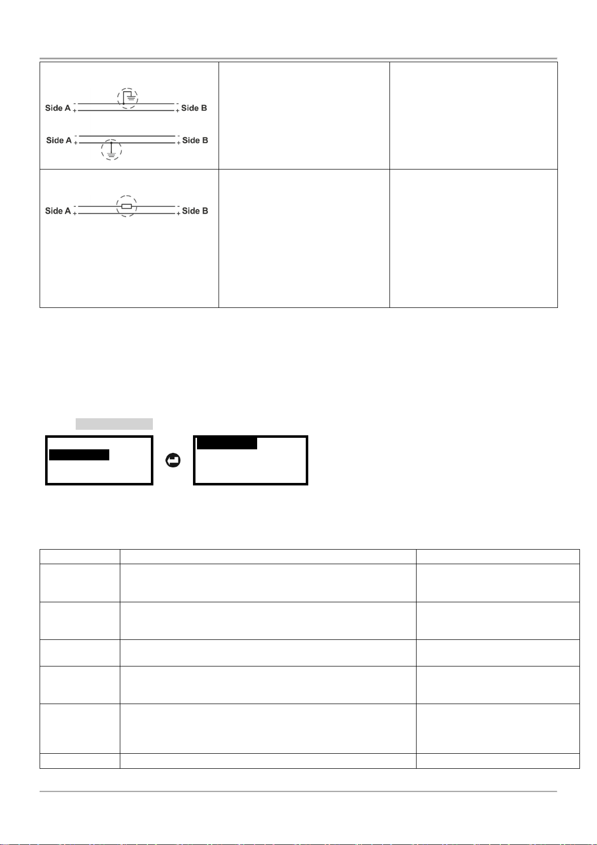
Earth fault in the cable
Run singe test “Leakage to Earth”
again to confirm the presence earth
fault in the positive or negative
cable wire. In case of fault the
tester will display message “Earth
fault”.
Search the earth fault as inspect
the grounding components in the
cable line, corrupted shield of the
cable, etc.
You can also use and the Bisection
method described in item 4.5.3.
Too High resistance
According the result in the Auto
Cable Test menu run the single test
for:
“R+ Cable”
“R- Cable”
“R Earth Cable”
In case of unusual high resistance
found the tester will display
message “R+/R-/Re=Too High”.
The error message “Too High” is
displayed when the detected
resistance in the positive cable
wire (R+), negative cable wire (R-)
or earth cable (Re) is higher than
400 Ohm. In such cases, it is
recommended to check the cable
and the joint connections
(terminals, base contacts). Check
also the cable length – it might be
too long.
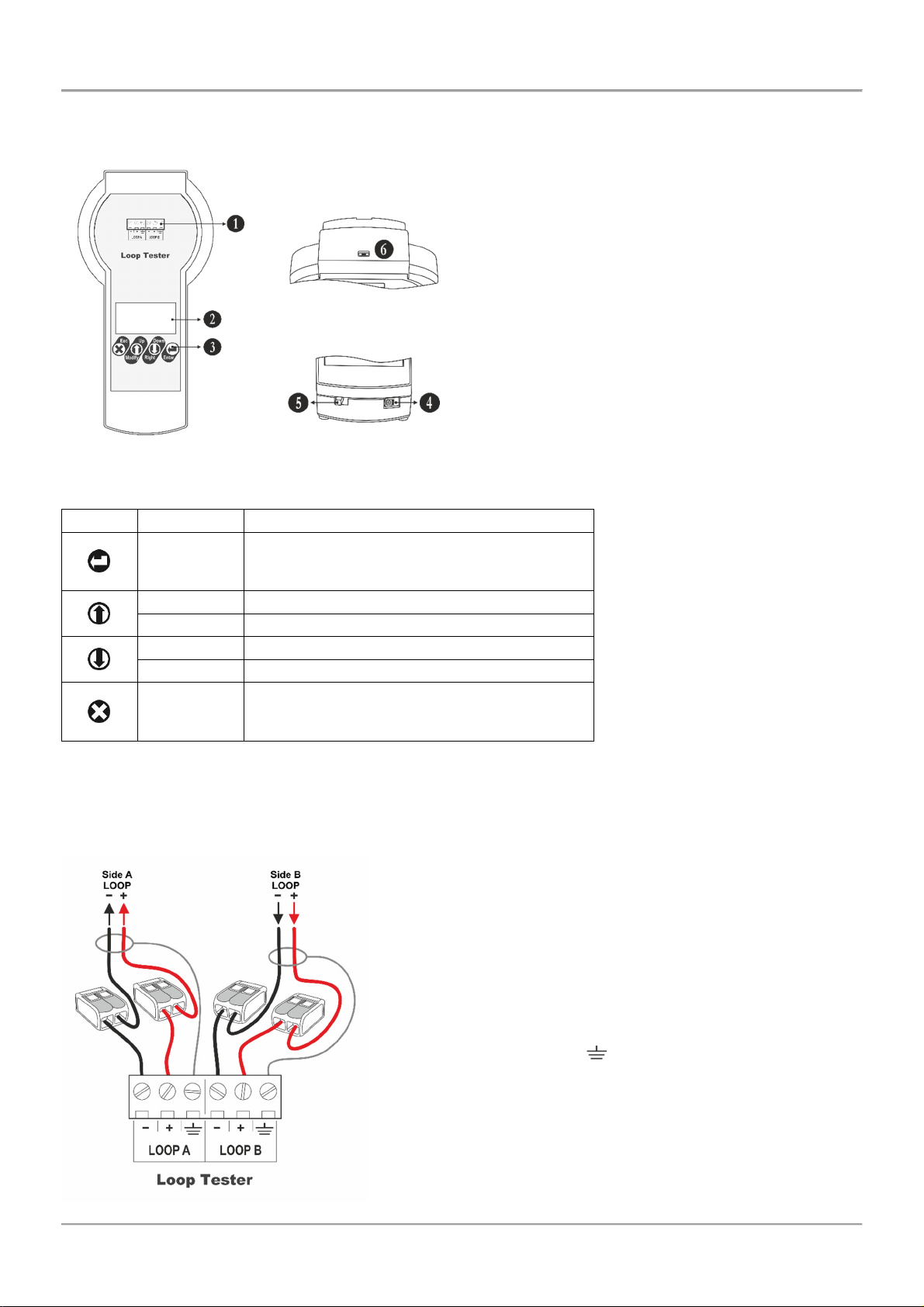
4.5 Perform Loop Tests
This is a menu for performing test of the loop and the connected devices. It is recommended to run first the “Loop
state” automatic test for reviewing the general state of the loop and a list of the connected devices. The general
review will help you at the beginning to orientate for current faults, possible breaks or short-circuits in the loop, the
number of connected devices and troubles with them.
4.5.1 Loop State
Cable tests
Loop Tests
Addressing
Language
Loop State
Loop Tools
Select “Loop State” menu and press ENTER. The message “Please wait” and a process bar are shown during
analysing the current loop state. The time for reading data can vary according the length and the number of
connected devices.
The general information is displayed as a list with short messages for the state and can be reviewed (scrolling
up/down) with arrow buttons:
Parameter Description State Messages
Short Side A
Shows the presence of short circuit at Loop Side A. In case of
fault “Yes” message, you can perform a detailed search using
menu “Loop Tools” – “Short / Break” (see item 4.5.5).
None – No fault
Yes – Short circuit detected at
side A.
Short Side B
Shows the presence of short circuit at Loop Side B. In case of
fault “Yes” message, you can perform a detailed search using
menu “Loop Tools” – “Short / Break” (see item 4.5.5).
None – No fault
Yes – Short circuit detected at
side B.
Earth Fault Shows the presence of earth fault in the loop. None – No fault
Yes – Earth fault detected.
Loop Break
Shows the presence of break in the loop. In case of fault “Yes”
message, you can perform a detailed search using menu “Loop
Tools” – “Short / Break” (see item 4.5.5).
None – No fault
Yes – Loop break detected.
No addr. Dev.
Shows the presence of devices with no set address in the loop.
Note: A possible reason for presence of devices with no set
address is performing the Loop State test for an unaddressed
loop.
None – No unaddressed devices
XXX – Number of found
unaddressed devices
Dbl. address Shows the presence of devices with double address in the loop. None – No double addresses