Comet Spa ETM Series Instruction manual

IT
EN
CS
FR
DE
ES
PL
FI
ITALIANO
ENGLISH
FRANÇAIS
ESPAÑOL
ČEŠTINA
DEUTSCH
POLSKI
SUOMI
SVENSKA
РУССКИЙ
SV
RU
EN •
Cold Water, Electric High Pressure Cleaners
Instruction manual - Use and Maintenance
FR •
Nettoyeurs Haute Pression Électriques à Eau Froide
Notice technique - Utilisation et Entretien
ES •
Hidrolavadoras Eléctricas de Agua Fría
Manual de Instrucciones - Uso y Mantenimiento
CS •
Vysokotlaké čističe na studenou vodu
Návod k používání - používání a Údržba
DE •
Elektrische Kaltwasser-Hochdruckreiniger
Bedienungs- und Wartungsanleitung
PL •
Myjki Elektryczne Zimnowodne
Instrukcja - Obsługi i Konserwacji
FI •
Sähköiset kylmävesipainepesurit
Opaskirja – Käyttö- ja huolto-opas
SV •
Elektriska högtryckstvättar med kallvatten
Bruks - och Underhållsanvisning
RU •
Электрические Гидроочистители Без Подогрева Воды
Руководство - Эксплуатация И Обслуживание
IT •
ATTENZIONE. Leggere le istruzioni prima di
utilizzare la macchina.
EN •
WARNING. Read the instructions before using the
machine
FR •
ATTENTION. Lire les instructions avant d’utiliser
l’appareil
ES •
ATENCIÓN. Leer atentamente las instrucciones
antes de utilizar la máquina.
CS •
POZOR. Před použitím zařízení si přečtěte návod
k použití.
DE •
ACHTUNG. Vor der Verwendung der Maschine die
Anweisungen lesen.
PL •
UWAGA. Przeczytać instrukcje przed użyciem
maszyny.
FI •
HUOMIO. Älä käytä laitetta, ennen kuin olet
lukenut ohjeet.
SV •
OBSERVERA. Läs instruktionerna innan maskinen
används.
RU •
ВНИМАНИЕ. Перед использованием
оборудования необходимо прочитать
данные инструкции.
IT •
IdropulItrIcI ElEttrIchE ad acqua FrEdda
ManualE d’IstruzIonE - uso EManutEnzIonE
ETM 150 X ETM 150 PRO
ETM seriesETM series
IT 8
EN 15
FR 22
ES 29
CS 36
DE 43
DE 50
DE 57
DE 64
RU 71

ETM 150 PROETM 150 PRO
ETM 150 XETM 150 X

ETM 150 PRO 1
3
1
4
2
6
7
8
5

2
23
21 22
20
9 10 11
12
13
15
14
18
19
S
A

3
11
16
17
A
B
24
17
2517

4
< 1.5 m (4.9 ft)
G
26

5
D
B
F
E
C

8
CARATTERISTICHE E DATI TECNICI
ETM 150 X ETM 150 PRO
COLLEGAMENTO ELETTRICO
Rete di alimentazione 230 V - 1~ 50 Hz
Potenza assorbita 2,9 kW
Fusibile 16 A
COLLEGAMENTO IDRAULICO
Massima temperatura acqua di alimentazione 60 °C-140 °F
Minima temperatura acqua di alimentazione 5 °C-41 °F
Minima portata acqua di alimentazione 750 l/h
198 US gph
Massima pressione acqua di alimentazione 0,8 MPa-8 bar-116 psi
Massima profondità di adescamento 1,5 m-4,9 ft
PRESTAZIONI
Portata massima 600 l/h
159 US gph
Pressione massima 15 MPa
150 bar
2176 psi
Forza di reazione sull'idropistola 27,9 N
Livello di pressione sonora
Incertezza (*) 82,2 dB(A)
0,8 dB(A) 73,2 dB(A)
0,8 dB(A)
Livello di potenza sonora (*) 96 dB(A) 86 dB(A)
Vibrazione sistema mano-braccio operatore
Incertezza (*) 2,3 m/s
2
0,24 m/s
2
MASSA E DIMENSIONI
Lunghezza x larghezza x altezza 460 x 200 x 325 mm
18,1 x 7,9 x 12,8 in 425 x 290 x 370 mm
16,7 x 11,4 x 14,6 in
Massa 27 kg-60 lb 35 kg-77 lb
(*) Misure eseguite in accordo ad EN 60335-2-79
Caratteristiche e dati sono indicativi. Il Costruttore si riserva il diritto di apportare all’apparecchio tutte le modiche ritenute opportune.
IT
ATTENZIONE
ISTRUZIONI ORIGINALI
Leggere e tener presente quanto riportato nel
MANUALE
D’ISTRUZIONE AVVERTENZE DI SICUREZZA.

9
IT
IDENTIFICAZIONE DEI COMPONENTI
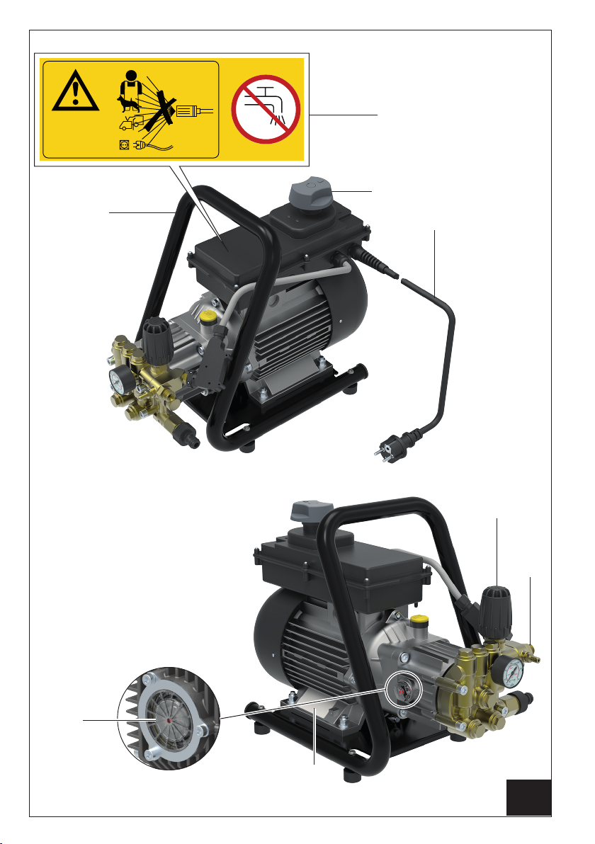
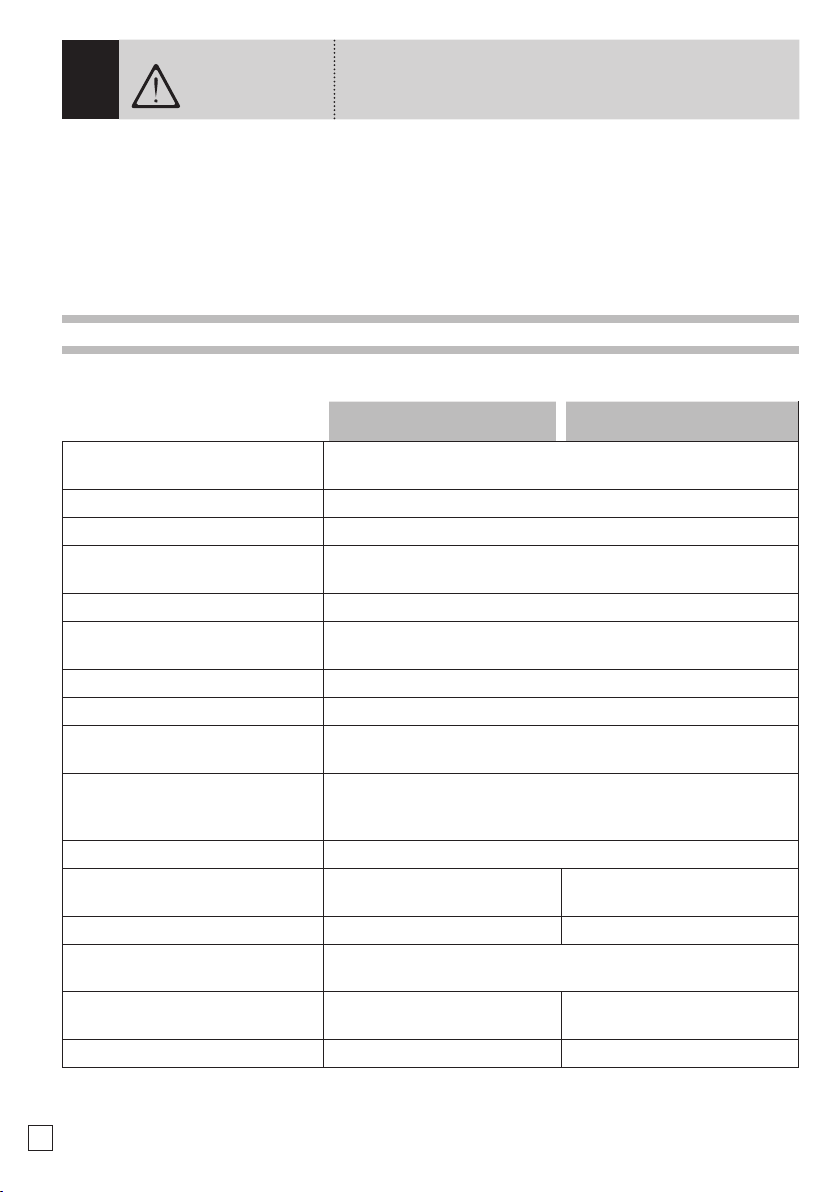
Fare riferimento alle gure 1, 2, 3, 4 e 5.
1. Interruttore generale
2. Impugnatura di trasporto
3. Targhetta di avvertenza. Informa sui rischi residui:
divieto di utilizzo per lavare persone, animali,
apparecchiature elettriche e l’idropulitrice
stessa. Avvisa che la macchina non è adatta al
collegamento alla rete idrica di acqua potabile
(qualora si intenda collegarla alla rete idrica
dell’acqua potabile, occorre utilizzare un
disconnettere di rete tipo
BA
, acquistabile presso
il proprio rivenditore).
4. Cavo elettrico di alimentazione
5. Spia livello olio
ETM 150 PRO
6. Manopola regolazione pressione
7. Raccordo uscita acqua
8. Targhetta di identicazione. Riporta il numero di
serie e le principali caratteristiche tecniche
9. Idropistola
10. Tubo lancia
11. Testina portaugello
12. Spillo pulizia ugello
13. Raccordo tubo alta pressione
14. Tubo alta pressione
15. Attacco rapido tubo alta pressione
16. Filtro tubo aspirazione detergente esterno
17. Tubo aspirazione detergente esterno
18. Fermo di sicurezza leva idropistola
19. Leva idropistola
20. Raccordo ingresso acqua
21. Filtro ingresso acqua
22. Guarnizione raccordo rapido d’ingresso acqua
23. Raccordo rapido d’ingresso acqua
24. Attacco aspirazione detergente da serbatoio
esterno
25. Fascetta elastica per ssaggio tubo aspirazione
detergente
26. Disconnettore di rete idrica tipo
BA
(non in
dotazione)
DISPOSITIVI DI SICUREZZA
• Protettore amperometrico.
Dispositivo che arresta il funzionamento dell’idropulitrice in caso di sovrassorbimento di corrente elettrica.
All’intervento occorre procedere come segue:
- portare l’interruttore generale (1) in posizione“0” e staccare la spina dalla presa di corrente;
- premere la leva (19) dell’idropistola, in modo da scaricare la eventuale pressione residua;
- attendere 10÷15 minuti, in modo da far rareddare l’idropulitrice;
- vericare che siano rispettate le prescrizioni di allacciamento alla linea elettrica (si veda il
MANUALE
D’ISTRUZIONE AVVERTENZE DI SICUREZZA
), con particolare riferimento alla prolunga impiegata;
- ricollegare la spina e ripetere la procedura di avviamento descritta al paragrafo “
FUNZIONAMENTO
”.
• Valvola di limitazione/regolazione della pressione.
Valvola, opportunamente tarata dal Costruttore, che permette di regolare la pressione di lavoro tramite
la manopola (6) e che consente al uido pompato di ritornare all’aspirazione della pompa, impedendo
l’insorgere di pressioni pericolose, quando si chiude l’idropistola o si cerca di impostare valori di pressione
al di sopra di quelli massimi consentiti.
• Dispositivo di bloccaggio della leva dell’idropistola.
Fermo di sicurezza (18) che consente di bloccare la leva (19) dell’idropistola (9) in posizione di chiusura,
prevenendone funzionamenti accidentali (Fig.2, PosizioneS).

10
DOTAZIONE STANDARD
Accertarsi che nella confezione del prodotto acquistato siano contenuti i seguenti elementi:
• idropulitrice ad alta pressione;
• tubo di mandata ad alta pressione con attacco rapido;
• idropistola;
• tubo lancia;
• kit raccordo di aspirazione;
• kit tubo aspirazione detergente esterno;
• manuale d’istruzione - avvertenze di sicurezza;
• manuale d’istruzione - uso e manutenzione;
• certicato di garanzia;
• dichiarazione CE di Conformità;
• spillo pulizia ugello.
In caso di problemi, rivolgersi al rivenditore o ad un centro di assistenza autorizzato.
ACCESSORI OPZIONALI
È possibile integrare la dotazione standard dell’idropulitrice con la seguente gamma di accessori:
• disconnettore di rete idrica tipo BA: obbligatorio per il collegamento alla rete idrica dell’acqua potabile.
• lancia sabbiante: ideata per levigare superci, eliminando ruggine, vernice, incrostazioni, ecc.;
• sonda spurgatubi: ideata per disotturare tubazioni e condutture;
• lancia ugello rotante: ideata per la rimozione di sporco ostinato;
• lancia schiumogena: ideata per una più ecace distribuzione del detergente;
• lance ed ugelli di vari tipi.
INSTALLAZIONE MONTAGGIO ACCESSORI
• Collegare il raccordo ad attacco rapido (15) del tubo (14) al raccordo di uscita acqua (7), avvitare e serrare.
OperazioneE di Fig.5.
• Avvitare il raccordo (13) del tubo alta pressione al letto dell’idropistola (9) e serrare a fondo con due chiavi
sse da 22 mm (non in dotazione). OperazioneD di Fig.5.
• Inserire il ltro (21) nel raccordo ingresso acqua (20). Inserire la guarnizione (22) nel raccordo rapido d’ingresso
acqua (23) ed avvitarlo al raccordo (20). OperazioneA di Fig.2.
FUNZIONAMENTO ATTIVITÀ PRELIMINARI
• Portare l’idropulitrice nella postazione di lavoro.
• Srotolare completamente il tubo alta pressione (14).
• Fissare al raccordo rapido d’ingresso acqua (23) un tubo di alimentazione utilizzando un comune raccordo
rapido da giardinaggio. OperazioneF di Fig.5.
• Aprire il rubinetto di alimentazione acqua, vericando che non vi siano gocciolamenti;
- nel caso che il collegamento venga eettuato alla rete idrica dell’acqua potabile, è obbligatorio utilizzare un
disconnettore di rete idrica tipo BA (26), conforme alla EN12729, acquistabile presso il proprio rivenditore
(si veda la Fig.4). Per il suo utilizzo riferirsi al relativo manuale d’istruzione;
- nel caso di alimentazione da un serbatoio di pescaggio, introdurre il tubo di aspirazione al suo interno,
accertandosi che la distanza verticale tra il livello dell’acqua e la pompa non sia superiore a 1,5m (4,9ft).
OperazioneG di Fig.4.
• Vericare che l’interruttore generale (1) sia in posizione“0” e collegare la spina. OperazioneC di Fig.5.
• Portare l’interruttore generale (1), in posizione“1”.
• Premere la leva (19) dell’idropistola ed attendere che fuoriesca un getto d’acqua continuo;
• Portare l’interruttore generale (1) in posizione“0” e collegare all’idropistola (9) il tubo lancia (10), serrando
a fondo. OperazioneB di Fig.5.

11
IT
FUNZIONAMENTO STANDARD AD ALTA PRESSIONE
• Vericare che la testina portaugello (11) non sia in posizione erogazione detergente, (si veda anche il
paragrafo “
FUNZIONAMENTO CON DETERGENTE
”).
• Riavviare l’idropulitrice portando in posizione“1” l’interruttore generale (1).
• Premere la leva (19) dell’idropistola, vericando che lo spruzzo dell’ugello sia uniforme e che non vi siano
gocciolamenti.
• Regolare, se necessario, la pressione agendo sulla manopola (6). Ruotare in senso orario per aumentare la
pressione, in senso antiorario per diminuirla.
FUNZIONAMENTO CON DETERGENTE
I detergenti raccomandati dal Costruttore, sono biodegradabili oltre il 90%.
Per le modalità di impiego, riferirsi a quanto riportato sull’etichetta della confezione di detergente.
• Portare l’interruttore generale (1) in posizione“0”.
• Inlare il tubo detergente (17) nel raccordo (24) posto sulla testata della pompa, allentando con una pinza
la fascetta elastica (25) come in Fig.3.
• Introdurre l’altro capo del tubo (17) comprensivo del ltro (16) nel serbatoio esterno, che sarà già stato
preparato con il detergente con la diluizione desiderata: anche in questo caso, seguire le raccomandazioni
relative al dosaggio riportate sulla targhetta della confezione di detergente.
• Agire sulla testina portaugello (11) come in Fig.3 - PosizioneA.
• Riavviare l’idropulitrice, portando l’interruttore generale (1) in posizione“1” ed azionare la leva (19):
l’aspirazione e la miscelazione avvengono automaticamente al passaggio dell’acqua.
• Per arrestare l’erogazione del detergente e ripristinare il funzionamento ad alta pressione, arrestare
l’idropulitrice, portando l’interruttore generale (1) in posizione“0” ed agire sulla testina (11) come in Fig.3-
PosizioneB.
INTERRUZIONE DEL FUNZIONAMENTO
• Con pressioni di lavoro superiori a 20bar/290psi, rilasciando la leva (19) dell’idropistola, mediante il
dispositivo Total-Stop l’idropulitrice si arresta automaticamente. Essa riprende a funzionare regolarmente
alla successiva pressione della leva dell’idropistola.
ARRESTO
• Chiudere completamente il rubinetto di alimentazione dell’acqua (oppure estrarre il tubo di aspirazione
dal serbatoio di pescaggio).
• Svuotare dall’acqua l’idropulitrice facendola funzionare per alcuni secondi con la leva (19) dell’idropistola
premuta.
• Portare l’interruttore generale (1) in posizione“0”.
• Togliere la spina di alimentazione dalla presa di corrente.
• Eliminare l’eventuale pressione residua rimasta nel tubo alta pressione (14), tenendo premuta per alcuni
secondi la leva (19) dell’idropistola.
• Attendere che l’idropulitrice si sia rareddata.
MESSA A RIPOSO
• Riavvolgere il tubo alta pressione (14) con cura, evitando piegature.
• Riavvolgere con cura il cavo di alimentazione (4).
• Riporre con cura l’idropulitrice in un luogo asciutto e pulito, facendo attenzione a non danneggiare il cavo
di alimentazione ed il tubo alta pressione.

12
MANUTENZIONE ORDINARIA
Eseguire le operazioni descritte nel paragrafo “ARRESTO”, attenendosi alla tabella seguente.
INTERVALLO DI
MANUTENZIONE INTERVENTO
Ad ogni uso •Controllo cavo di alimentazione, tubo alta pressione, raccordi, idropistola, tubo lancia.
Qualora uno o più particolari risultassero danneggiati, non utilizzare assolutamente
l’idropulitrice e rivolgersi ad un Tecnico Specializzato.
Settimanalmente • Pulizia ltro ingresso acqua (21).
Svitare il raccordo rapido (23) ed estrarre il filtro (21). Per la pulizia, in genere
è sufficiente passare il filtro sotto un getto d’acqua corrente, o soffiarlo con
aria compressa. Nei casi più difficili, usare un prodotto anticalcare o sostituirlo,
rivolgendosi per l’acquisto del ricambio ad un centro assistenza autorizzato.
Rimontare il ltro e riavvitare il raccordo rapido.
Mensilmente • Pulizia ugello.
Per la pulizia, in genere è suciente passare dentro il foro dell’ugello lo spillo (12)
in dotazione. Qualora non si ottengano risultati apprezzabili, sostituire l'ugello,
rivolgendosi per l'acquisto del ricambio ad un centro di assistenza autorizzato. L'ugello
è sostituibile sfruttando una chiave da 14 mm (non in dotazione).
• Pulizia ltro aspirazione detergente (16)
Per la pulizia, in genere è suciente passare il ltro sotto un getto d’acqua corrente,
o soarlo con aria compressa. Nei casi più dicili, usare un prodotto anticalcare o
sostituirlo, rivolgendosi per l’acquisto del ricambio ad un centro assistenza autorizzato.
• Verica livello olio pompa [ETM 150 PRO].
Sfruttare l’indicatore (5) (Fig.1). Se sono necessari rabbocchi, rivolgersi ad un Tecnico
Specializzato.
MANUTENZIONE STRAORDINARIA
La manutenzione straordinaria deve essere effettuata esclusivamente da un Tecnico Specializzato,
attenendosi alla tabella seguente (dati indicativi).
INTERVALLO DI
MANUTENZIONE INTERVENTO
Ogni 200 ore • Controllo circuito idraulico (acqua) pompa. • Controllo ssaggio pompa.
Ogni 500 ore • Sostituzione olio pompa.
• Controllo valvole aspirazione/mandata pompa.
• Controllo serraggio viti pompa.
• Controllo valvola di regolazione
pompa.
• Verica dei dispositivi di sicurezza.

13
IT
INCONVENIENTI, CAUSE E RIMEDI
INCONVENIENTI CAUSE RIMEDI
Portando l’interruttore(1) in
posizione“1”, l’idropulitrice
non si avvia.
Intervento dispositivo di protezione
dell’impianto a cui è collegata
l’idropulitrice (fusibile, interruttore
dierenziale ecc.).
Ripristinare il dispositivo di protezione.
IN CASO DI NUOVO INTERVENTO
NON UTILIZZARE L’IDROPULITRICE
E RIVOLGERSI AD UN TECNICO
SPECIALIZZATO.
Spina non inserita correttamente. Scollegarelaspinae ricollegarla correttamente.
L’idropulitrice vibra molto ed
è rumorosa. Filtro ingresso acqua (21) sporco. Attenersi a quanto riportato nel paragrafo
“MANUTENZIONE ORDINARIA".
Aspirazione d’aria. Controllarel’integrità delcircuitod’aspirazione.
Alimentazione idrica insuciente o
eccessivaprofonditàdi adescamento. Vericare che il rubinetto sia completamente
aperto e che la portata della rete idrica
o la profondità di adescamento siano
conformi a quanto riportato nel paragrafo
“
FUNZIONAMENTO ATTIVITÀ
PRELIMINARI
" Fig.4 - OperazioneG.
L'idropulitrice non raggiunge
la massima pressione. Valvola di regolazione impostata per
un valore inferiore a quello massimo. Ruotare in senso orario la manopola (6).
Testina portaugello (11) in bassa
pressione (g. 3 - PosizioneA).Operare come in Fig.3 - PosizioneB.
Ugello usurato. Sostituire l’ugello secondo quanto
riportato nel paragrafo
“MANUTENZIONE
ORDINARIA".
Alimentazione idrica insuciente o
eccessivaprofonditàdi adescamento. Vericare che il rubinetto sia completamente
aperto e che la portata della rete idrica
o la profondità di adescamento siano
conformi a quanto riportato nel paragrafo
“FUNZIONAMENTO ATTIVITÀ
PRELIMINARI"
Fig.4 - OperazioneG.
Funzionamento anomalo del
disconnettore di rete idrica tipo BA Vedi pari tabella contemplata nel relativo
manuale di istruzione
Scarsa aspirazione
detergente. Testina portaugello (11) non in bassa
pressione (Fig.3 - PosizioneB). Operare come in Fig.3 - PosizioneA.
Filtro aspirazione detergente (16)
otturato. Attenersi a quanto riportato nel paragrafo
“MANUTENZIONE ORDINARIA".
Detergente troppo viscoso. Utilizzare un detergente raccomandato
dal Costruttore, attenendosi alle diluizioni
riportate sulla targhetta.
(continua a pagina seguente)

14
INCONVENIENTI CAUSE RIMEDI
Dall’ugello non esce acqua. Manca l’acqua. Verificare che il rubinetto della rete idrica
sia completamente aperto o che il tubo di
aspirazione possa adescare.
Funzionamento anomalo del
disconnettore di rete idrica tipo
BA
Vedi pari tabella contemplata nel relativo
manuale di istruzione
Eccessiva profondità d’aspirazione. Vericare che la profondità di adescamento
sia conforme a quanto riportato nel
paragrafo
“FUNZIONAMENTO ATTIVITÀ
PRELIMINARI"
Fig.4- OperazioneG.
Ugello acqua otturato. Pulire e/o sostituire l’ugello secondo quanto
riportato nel paragrafo
“MANUTENZIONE
ORDINARIA".
L’idropulitrice si arresta
durante il funzionamento. Intervento dispositivo di protezione
dell’impianto a cui è collegata
l’idropulitrice (fusibile, interruttore
dierenziale ecc.).
Ripristinare il dispositivo di protezione.
IN CASO DI NUOVO INTERVENTO
NON UTILIZZARE L’IDROPULITRICE
E RIVOLGERSI AD UN TECNICO
SPECIALIZZATO.
Intervento dispositivo di protezione
amperometrico. Attenersi a quanto riportato nel paragrafo
“DISPOSITIVI DI SICUREZZA"
.
L'idropulitrice si riavvia
spontaneamente. Perdite e/o gocciolamenti nel circuito
di mandata. Controllare l'integrità del circuito di mandata.
Ruotando l’interruttore
generale (1) il motore ronza,
ma non parte.
Impianto elettrico e/o prolunga non
adeguati. Verificare il rispetto delle prescrizioni di
allacciamento alla linea elettrica (si veda il
MANUALE D'ISTRUZIONE AVVERTENZE
DI SICUREZZA
), con particolare riferimento
alla prolunga impiegata.

15
EN
TECHNICAL CHARACTERISTICS AND SPECIFICATIONS
ETM 150 X ETM 150 PRO
ELECTRICAL CONNECTIONS
Power supply 230 V - 1~ 50 Hz
Input 2,9 kW
Fuse 16 A
HYDRAULIC CONNECTION
Maximum water supply temperature 60 °C-140 °F
Minimum water supply temperature 5 °C-41 °F
Minimum water supply ow rate 750 l/h
198 US gph
Maximum water supply pressure 0,8 MPa-8 bar-116 psi
Maximum priming depth 1,5 m-4,9 ft
PERFORMANCES
Max. ow rate 600 l/h
159 US gph
Maximum pressure 15 MPa
150 bar
2176 psi
Reaction force on the gun 27,9 N
Sound pressure level - Uncertainty (*) 82,2 dB(A)
0,8 dB(A) 73,2 dB(A)
0,8 dB(A)
Sound power level (*) 96 dB(A) 86 dB(A)
Operator arm-hand system vibration -
Uncertainty(*) 2,3 m/s
2
0,24 m/s
2
WEIGHT AND DIMENSIONS
Length x Width x Height 460 x 200 x 325 mm
18,1 x 7,9 x 12,8 in 425 x 290 x 370 mm
16,7 x 11,4 x 14,6 in
Weight 27 kg-60 lb 35 kg-77 lb
(*) Measurements taken in compliance with EN 60335-2-79
The characteristics and specications are guidelines only. The manufacturer reserves the right to make all modications to the equipment deemed necessary.
EN
WARNING
TRANSLATION OF THE ORIGINAL INSTRUCTIONS
Read and keep in mind that indicated in the
INSTRUCTION
MANUAL SAFETY WARNINGS.

16
IDENTIFICATION OF COMPONENTS
Refer to gures 1, 2, 3, 4 and 5.
1. TMaster switch
2. Transport grip
3. Warningplate.Informs aboutresidualrisks: notto be
used to wash people, animals, electrical apparatus
and the high-pressure cleaner itself. Warns that
the machine is unsuitable for connecting up to
the drinking water mains (to connect up to the
water mains, a
BA
type mains disconnector will be
requiredwhichcan bepurchased from yourdealer).
4. Power cable
5. Oil level indicator
ETM 150 PRO
6. Pressure adjustment knob
7. Water outlet connection
8. Identication plate. Shows the serial number and
main technical specications.
9. Spray gun
10. Lance hose
11.Nozzle holder head
12. Nozzle cleaning pin
13. High-pressure hose connection
14. High-pressure hose
15. High-pressure hose quick coupling
16. External detergent suction hose lter
17. External detergent suction hose
18. Spray gun lever safety stop
19. Spray gun lever
20. Water inlet connection
21. Water inlet lter
22. Water inlet quick-t connection seal
23. Water inlet quick-t connection
24. External tank detergent suction coupling
25. Elastic clamp for fastening the detergent suction
hose
26.
BA
type water mains disconnector (not supplied)
SAFETY DEVICES
• Ampere cut-out protection device.
This device stops the high-pressure cleaner operation in the event of excessive power absorption.
If it trips, proceed as follows:
- move the master switch (1) to “0”position and remove the plug from the power socket;
- press the spray gun lever (19), so as to release any residual pressure;
- wait 10÷15 minutes for the high-pressure cleaner to cool down;
- make sure the instructions for connection to the power supply are complied with (refer to the
INSTRUCTION
MANUAL SAFETY PRECAUTIONS
), with special reference to the extension used;
- t the plug back in the socket and repeat the start procedure described in the paragraph “
OPERATION
”.
• Pressure unloader/regulation valve.
Valve suitably set by the Manufacturer, which permits regulating the operating pressure by means of the
knob (6) and which allows the pumped uid to return to pump suction, preventing the occurrence of
hazardous pressures when the spray gun is closed or whenever an attempt is made to set pressure values
above max. allowed pressure.
• Spray gun lever lock device.
Safety stop (18) which allows locking the lever (19) of the spray gun (9) in closed position, thus preventing
accidental operation (g. 2, position S).

17
EN
STANDARD FITTINGS
Make sure the following are contained in the purchased product pack:
• high-pressure cleaner;
• high-pressure delivery hose with quick coupling;
• spray gun;
• lance hose;
• suction connection kit;
• external detergent suction hose kit;
• instruction manual - safety precautions;
• instruction manual - operation and maintenance;
• warranty certicate;
• EC declaration of conformity;
• nozzle cleaning pin.
In case of problems, contact your dealer or an authorised after-sales centre.
OPTIONAL ACCESSORIES
The standard ttings of the high-pressure cleaner can be integrated with the following range of accessories:
•
BA
type water mains disconnector: mandatory for connecting up to the drinking water mains.
• sandblasting lance: designed to clean surfaces, eliminating rust, paint, scale, etc.;
• drain cleaning kit: designed to unblock pipes and ducts;
• rotating-nozzle lance: designed to remove resistant dirt;
• foam lance: designed for more eective detergent distribution;
• lances and nozzles of various types.
INSTALLATION FITTING ACCESSORIES
• Connect the quick coupling (15) of the hose (14) to the water outlet connection (7), screw down and secure.
Operation E in g. 5.
• Screw up the connection (13) of the high-pressure hose to the thread of the spray gun (9) and tighten well
using two 22mm xed wrenches (not supplied). Operation D in g. 5.
• Fit the lter (21) in the water inlet connection (20). Fit the seal (22) in the water inlet quick-t connection(23)
and screw up to the connection (20). Operation A in g. 2.
OPERATION PRELIMINARY ACTIVITIES
• Move the high-pressure cleaner to work position.
• Completely unwind the high-pressure hose (14).
• Attach a supply pipe to the water inlet’s quick connection (23) using a normal garden connector. OperationF
in g. 5.
• Open the water supply tap and make sure this is not dripping;
- if the connection is made to the drinking water mains, a
BA
type water mains disconnector (26) must be
used, in conformity with EN 12729 standard, and available from your dealer (g. 4).With regard to its use,
refer to the relative instruction manual;
- in case of supply from a water tank, introduce the suction hose inside the tank and make sure the vertical
distance between the water level and the pump is no more than 1.5m (4.9ft). Operation G in g. 4.
• Make sure the master switch (1) is on “0” position and insert the plug. Operation C in g. 5.
• Move the master switch (1) to position “1”.
• Press the spray gun lever (19) and wait for a continuous jet of water to come out;
• Move the master switch (1) to “0” position and connect the lance hose (10) to the spray gun (9), tightening
well. operation B in g. 5.

18
STANDARD OPERATION HIGH PRESSURE
• Make sure the nozzle holder head (11) is not in the detergent dispensing position (refer to “
OPERATION
WITH DETERGENT
” paragraph).
• Start the high-pressure cleaner again moving the master switch (1) to position “1”.
• Press the gun spray lever (19), making sure the spray of the nozzle is even and this is not dripping.
• If necessary, adjust the pressure by turning the knob (6).Turn clockwise to increase pressure, anticlockwise
to decrease it.
OPERATION WITH DETERGENT
The detergents recommended by the Manufacturer are over 90% biodegradable.
For instructions on how to use them, refer to the indications on the label of the detergent pack.
• Move the master switch (1) to “0” position.
• Insert the detergent hose (17) in the connection (24) on the pump head, loosening the elastic clamp (25)
using pliers as shown in g. 3.
• Introduce the other end of the hose (17) including the lter (16) into the external tank, which will already
have been prepared with the detergent with the required dilution. In this case as well, follow the suggestions
relating to dosage shown on the label of the detergent pack.
• Operate on the nozzle holder head (11) as shown in g. 3- positionA.
• Start the high-pressure cleaner again, moving the master switch (1) to position “1” and operate the lever(19):
suction and mixing occur automatically as the water ows through.
• To stop the supply of detergent and restore high-pressure operation, stop the high-pressure cleaner moving
the master switch (1) to “0”position and operate on the head (11) as shown in g. 3- positionB.
STOPPING OPERATION
• With operating pressures above 20 bar / 290 psi, the high-pressure cleaner automatically stops by releasing
the spray gun lever (19), through the Total-Stop device. It starts operating again when pressing the spray
gun lever.
STOP
• Completely close the water supply tap (or remove the suction hose from the water tank).
• Empty the water from the high-pressure cleaner, allowing this to operate for a few seconds with the spray
gun lever (19) pressed.
• Move the master switch (1) to “0” position.
• Remove the plug from the power socket.
• Eliminate any residual pressure in the high-pressure hose (14), by keeping the spray gun lever (19) pressed
for a few seconds.
• Wait for the high-pressure cleaner to cool down.
DECOMMISSIONING
• Re-wind the high-pressure hose (14) carefully, avoiding any folds.
• Re-wind the power cable (4) carefully.
• Store the high-pressure cleaner in a dry and clean place, making sure not to damage the power cable and
the high-pressure hose.

19
EN
ROUTINE MAINTENANCE
Perform the operations described in the
“STOP”
paragraph, following the chart shown below.
MAINTENANCE
SCHEDULE JOB
After every use •Check the power cable, high-pressure hose, connections, spray gun and lance hose.
If any of these is damaged, do not use the high-pressure cleaner and contact a Skilled
Technician.
Weekly • Clean the water inlet lter (21).
Unscrew the quick-t connection (23) and take out the lter (21). Generally speaking,
to clean this all that need be done is pass the lter under a jet of running water
or blow on it with compressed air. In the most difficult cases, use an anti-scale
product or replace the lter. To buy spares contact an authorised after-sales centre.
Fit the lter back on and screw the quick-t connection back on.
Monthly • Clean the nozzle.
Generally speaking, to clean the nozzle, it is enough to pass the pin (12) provided
through the nozzle hole. If this is not successful, change the nozzle. Buy this from an
authorised after-sales centre. The nozzle can be changed using a 14mm wrench (not
supplied).
• Clean the detergent suction lter (16)
.
Generally speaking, to clean the lter, all you need do is pass it under a jet of running
water or blow it with compressed air. In the most dicult cases, use an anti-scale product
or replace it. Only buy spares from authorised after-sales centres.
• Check the pump oil level
ETM 150 PRO.
Use the indicator (5) (g. 1). If topping up is required, contact a Skilled Technician.
SPECIAL MAINTENANCE
Special maintenance jobs must only be performed by a Skilled Technician, following the table below
(indicative data).
MAINTENANCE
SCHEDULE JOB
Every 200 hours • Check the pump (water) hydraulic circuit. • Check the pump fastening.
Every 500 hours • Pump oil change.
• Check the pump suction/delivery valves.
• Check the tightness of the pump screws.
• Check the pump regulation valve.
• Check the safety devices.

20
TROUBLESHOOTING
PROBLEMS CAUSES REMEDIES
When the switch (1) is
moved to position“1”,
the high-pressure cleaner
does not start.
Tripping of system cutout device to
which the high-pressure cleaner is
connected (fuse, RCCB, etc.).
Reset the cutout device.
IN CASE THIS TRIPS AGAIN, DO NOT USE THE
HIGHPRESSURE CLEANER AND CONTACT A
SKILLED TECHNICIAN.
The plug is not properly tted. Disconnect the plug and t it back correctly.
The high-pressure cleaner
vibrates a lot and is noisy. Water inlet lter (21) dirty. Follow the indications of the
“ROUTINE
MAINTENANCE”
paragraph.
Suction of air. Check the integrity of the suction circuit.
Not enough water supply or too
much priming depth. Make sure the tap is completely open and that the
water mains ow or priming depth are in conformity
with the indications of the paragraph
“OPERATION
PRELIMINARY ACTIVITIES”
g.4- Operation G.
The high-pressure cleaner
fails to reach maximum
pressure.
Unloader/regulation valve set at
a lower value than the maximum
one.
Turn the knob (6) clockwise.
Nozzle holder head (11) in low-
pressure mode (g. 3 - PositionA).Refer to g. 3 - Position B.
Worn nozzle. Replace the nozzle as indicated in the
“ROUTINE
MAINTENANCE”
paragraph.
Not enough water supply or too
much priming depth. Make sure the tap is completely open and that the
water mains ow or priming depth are in conformity
with the indications of the paragraph
“OPERATION
PRELIMINARY ACTIVITIES”
g.4- Operation G.
Faulty operation of the BA type
water mains disconnector See table in relative instruction manual.
Low detergent suction Nozzle holder head (11) not in low-
pressure mode (g. 3 - PositionB).Refer to g. 3 - Position A.
Detergent suction filter (16)
clogged. Follow the indications of the
“ROUTINE
MAINTENANCE
”paragraph.
Detergent too viscous. Use a detergent recommended by the Manufacturer,
and dilute in accordance with plate instructions.
No water comes out of the
nozzle. No water. Make sure the water mains tap is completely open
or the suction hose can prime.
Faulty operation of the
BA
type
water mains disconnector. See table in relative instruction manual.
Too much suctioning depth. Make sure the priming depth is in conformity with
the indications of the paragraph
“OPERATION
PRELIMINARY ACTIVITIES”
g. 4 - Operation G.
Water nozzle clogged. Clean and/or replace the nozzle as indicated in the
“ROUTINE MAINTENANCE”
paragraph.
(continued on next page)
This manual suits for next models
2
Table of contents
Languages:
Other Comet Spa Pressure Washer manuals