508107-01Issue 2041
Page 9 of 55
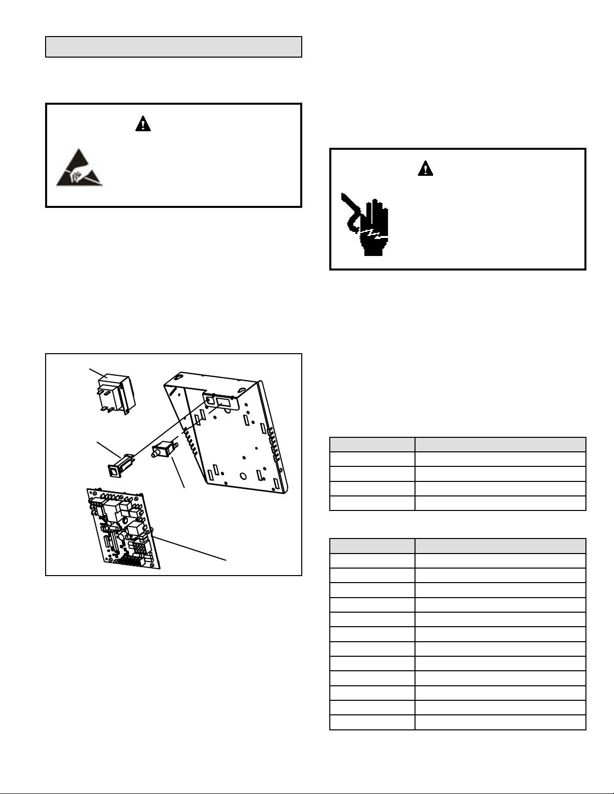
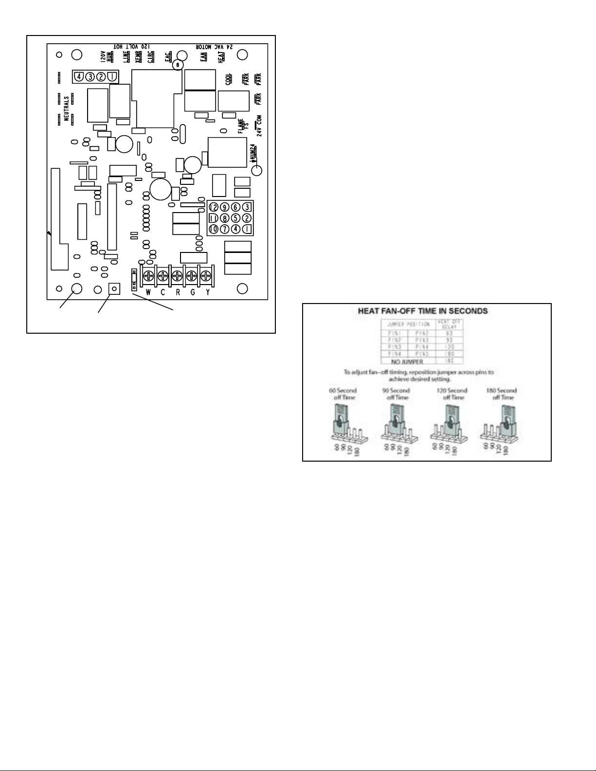
Figure 3. Integrated Control
(Automatic Hot Surface Ignition System)
BLOWER OFF DELAY
RED LED RECALL BUTTON
Electronic Ignition
On a call for heat the integrated control monitors the
combustion air inducer pressure switch. The control board
will not begin the heating cycle if the pressure switch is
closed (by-passed). Once the pressure switch is determined
to be open, the combustion air inducer is energized. When
the dierential in the pressure switch is great enough, the
pressure switch closes and a 15-second pre-purge begins.
If the pressure switch is not proven within 2-1/2 minutes,
the integrated control goes into Watchguard-Pressure
Switch mode for a 5-minute re-set period.
After the 15-second pre-purge period, the ignitor warms
up for 20 seconds during which the gas valve opens at
19 seconds for a 4-second trial for ignition. The ignitor
remains energized for the rst 3 seconds during the 4
second trial. If ignition is not proved during the 4-second
period, the integrated control will try four more times with
an inter purge and warm-up time between trials of 35
seconds. After a total of ve trials for ignition (including the
initial trial), the integrated control goes into Watchguard-
Flame Failure mode. After a 60-minute reset period, the
integrated control will begin the ignition sequence again.
Fan Time Control
Heating Fan On Time
The fan on time of 30 seconds is not adjustable.
Heating Fan O Time
Fan o time (time that the blower operates after the heat
demand has been satised) can be adjusted by moving
the jumper to a dierent setting. The unit is shipped with
a factory fan o setting of 90 seconds. For customized
comfort, monitor the supply air temperature once the heat
demand is satised. Note the supply air temperature at the
instant the blower is de-energized.
Adjust the fan-o delay to achieve a supply air temperature
between 90° - 110° at the instant the blower is de-energized.
(Longer delay times allow for lower air temperature, shorter
delay times allow for higher air temperature). See Figure 4.
Cooling Fan On Time
The fan on time is 2 seconds and is not adjustable.
Cooling Fan O Time
The control has a 45 second fan o delay after cooling
demand has been met. This delay is factory set and not
adjustable.
Figure 4.
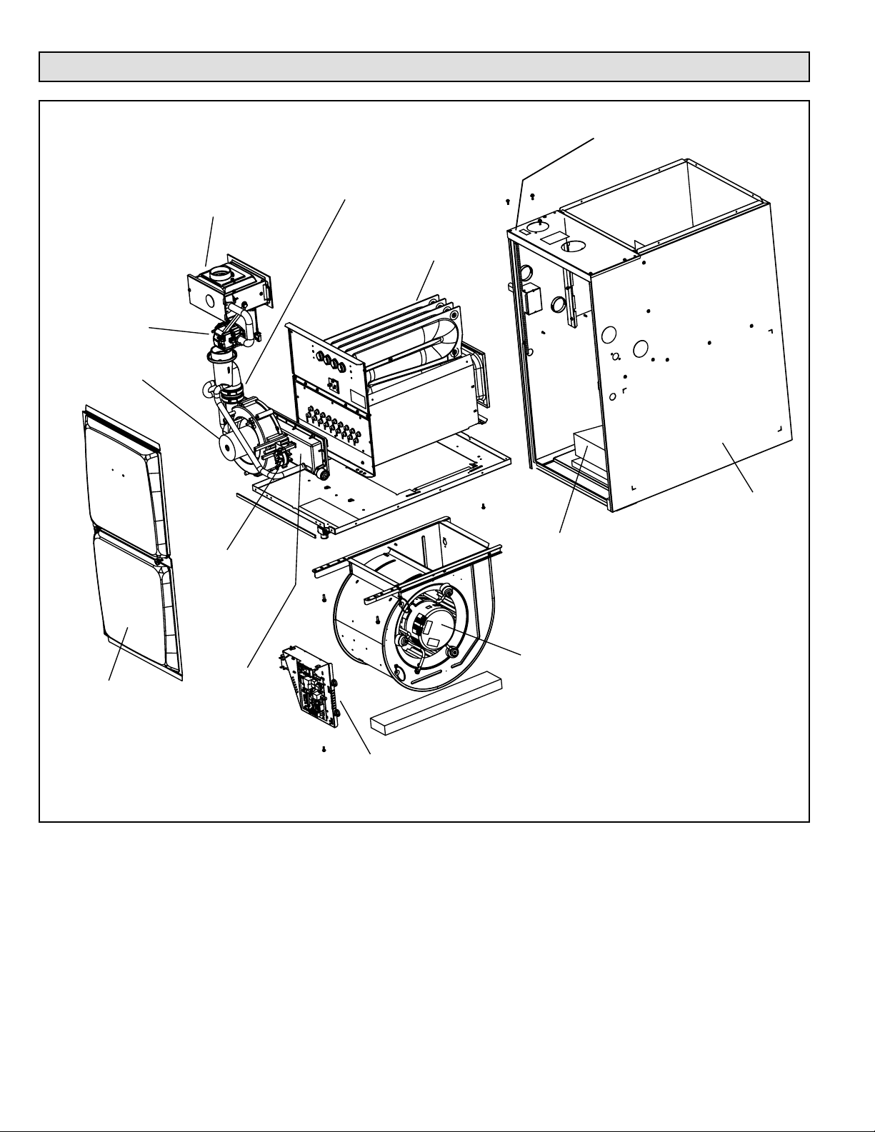
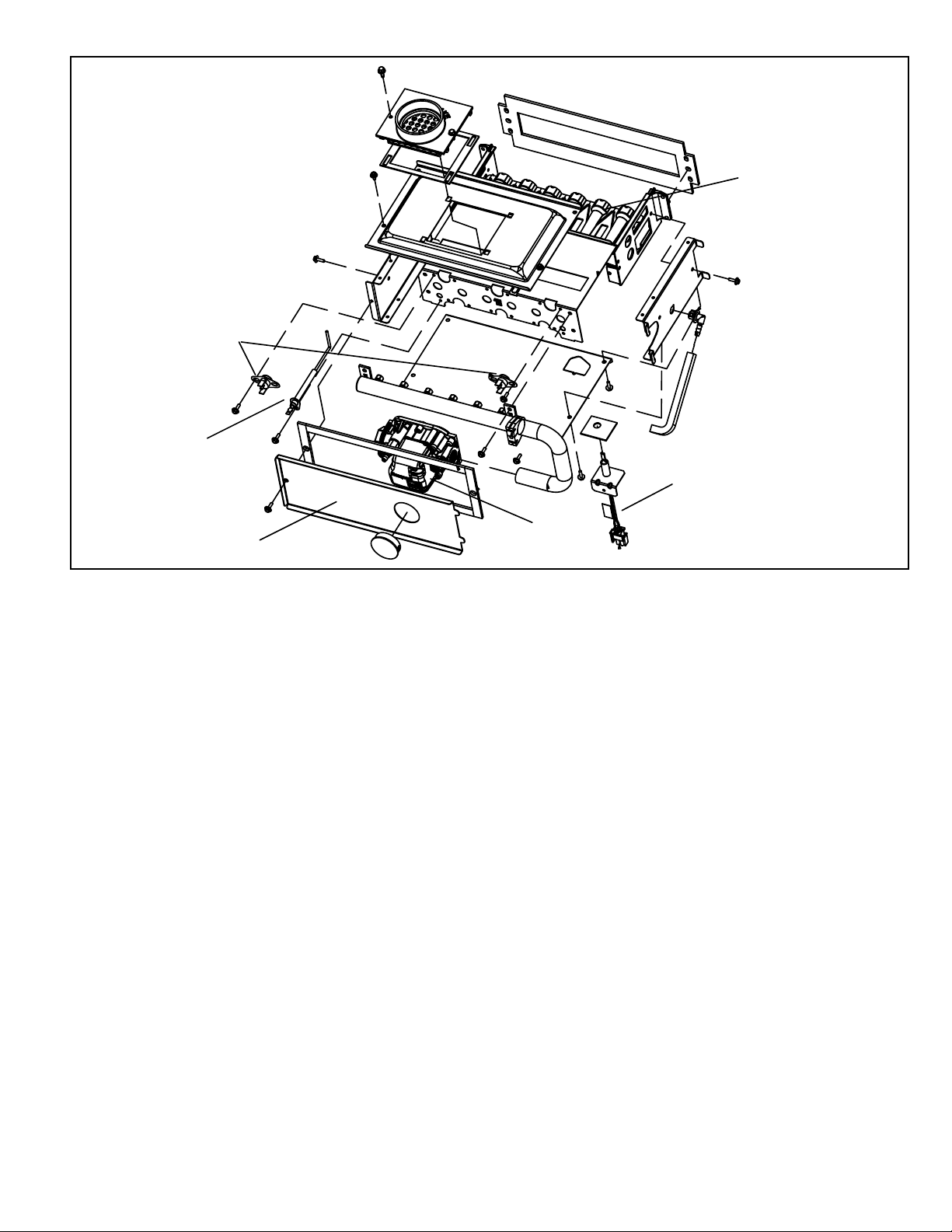
Heating Components
Combustion air inducer (B6), primary limit control (S10),
ignitor, burners, ame rollout switch (S47), gas valve
(GV1), combustion air pressure switch (S18), and heat
exchangers are located in the heating compartment. The
heating compartment can be accessed by removing the
outer access panel.
GUH92C units use a nitride ignitor made from a
proprietary ceramic material. To check ignitor, measure
its resistance and voltage. A value of 39 to 70 ohms
indicates a good ignitor. Voltage to the ignitor should be
102 - 132VAC. See Figure 9 for resistance and voltage
checks.